background image

 
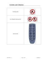
Controls and Indicators 

(MAN-0013-A) 

Page 13 of 47 

DCR-00422 


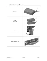
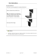
AC Input 


Battery 

(Optional) 


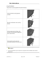
Handrail Release 


Single Pedal Braking 


Summary of Contents for UltraScan Versa Primer

Page 1: ...MAN 0013 A Page 1 of 47 DCR 00422 User Manual Owner _____________________ Model _____________________ Serial _____________________ Date _____________________...

Page 2: ...17 Surface Height Adjustment 17 Fowler Adjustment 17 Calf Adjustment 17 Trendelenburg Adjustment 18 Memory Function 18 Hand Control Lock Unlock 19 Under bed Lights 19 Using the Integrated Arm Boards...

Page 3: ...ding allowable patient leakage current Warning Caution Any terminal which is intended for connection to an external protective conductor for protection against electric shock in case of a fault In acc...

Page 4: ...gs and should be carefully reviewed WARNING Identifies a situation that could result in injury to the patient or caregiver CAUTION Identifies a situation that could result in equipment damage Note Pro...

Page 5: ...eptacle marked hospital only or hospital grade If damage has occurred to the power cord immediately remove the cord from service Failure to do so could result in serious injury or death The battery sh...

Page 6: ...facturer s instructions and warnings before using any cleaning product or disinfectant Refer to instructions located in this manual for vinyl cleaning recommendations Substances such as imaging gels a...

Page 7: ...t is not intended for use in oxygen rich environments Safety Features This product is equipped with multiple automated safety features to prevent danger or damage during use The entire system is elect...

Page 8: ...for use STEP ACTION 1 After removing packaging materials locate the primary power supply cord and attach to a suitable grounded power outlet 2 To test actuator function locate the hand control and dep...

Page 9: ...roduct Illustration Model 292 Item Description 1 Base 2 Seat Section 3 Fowler Section 4 Calf Section 5 Footboard 6 Handrail 7 Caster 8 Pedal 9 Stirrup 10 Imaging Drop Section 11 Sonographer s Drop Sec...

Page 10: ...ration MAN 0013 A Page 10 of 47 DCR 00422 Model 992 Item Description 1 Base 2 Seat Section 3 Fowler Section 4 Calf Section 5 Footboard 6 Integrated Armboard 7 Caster 8 Pedal 9 Stirrup Optional feature...

Page 11: ...MAN 0013 A Page 11 of 47 DCR 00422 Controls and Indicators Unique Device Identification Label Serial Item Item Description Unique Identifier Certification Label Refer to Manual Label...

Page 12: ...Controls and Indicators MAN 0013 A Page 12 of 47 DCR 00422 No Sitting label No Sitting No Standing Label Hand Control...

Page 13: ...Controls and Indicators MAN 0013 A Page 13 of 47 DCR 00422 AC Input Battery Optional Handrail Release Single Pedal Braking...

Page 14: ...Controls and Indicators MAN 0013 A Page 14 of 47 DCR 00422 Drop Section Back Rest Release Drop Section Remote Release Integrated Arm Board Release...

Page 15: ...ry Information for indicator information and proper care for batteries WARNING To reduce the risk of electrical shock grounding reliability can only be achieved when the equipment is connected to an e...

Page 16: ...ide of the base and are used to adjust the caster function WARNING To reduce the risk of a potential injury lock casters before using equipment Once the product and patient have been properly position...

Page 17: ...the product to reach the lowest chair position the seat section must be level or in a Trendelenburg position Level position may be achieved using the Trendelenburg function on the hand control The pr...

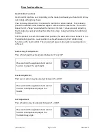
Page 18: ...l function to independently adjust the Trendelenburg angle Memory Function The product has the ability for the user to set two unique memory positions Set the product to the desired position To set a...

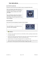
Page 19: ...The product may be equipped with optional under bed lights Press both height up down buttons to turn on off the under bed lights WARNING Verify the area around the product is free of impediments befo...

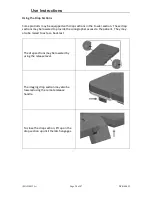
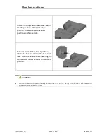
Page 20: ...These drop sections may be lowered to provide the sonographer access to the patient They may also be raised to act as a back rest The drop sections may be lowered by using the release lever The imagin...

Page 21: ...are two back rest positions to choose from To lower from the back rest position rotate the lever to release the back rest lock Hold the handle while lowering the drop section until it returns to its s...

Page 22: ...arm boards may also be raised into a backrest position To position the arm board lift and rotate outward to the desired position To store the arm board rotate inward until the arm board is in its lock...

Page 23: ...adjust the stirrup position lift slightly on the stirrup bar and rotate outward until the bar clicks into the next position Once the procedure is complete rotate the stirrup back to its initial posit...

Page 24: ...ocedural use Note The footboard is not intended for standing The footboard should be raised to its stored position when a patient enters the product in a chair position Raise upward for storage WARNIN...

Page 25: ...mounting bracket outward Place the handrail into the mounting bracket Pull the release lever and lower the handrail so the locking pin engages the hole in the handrail The handrails may be lowered or...

Page 26: ...charged when the product is plugged into AC power Note The lifting capacity and speed of the product may be reduced while on battery power WARNING Equipment should only be serviced by authorized pers...

Page 27: ...e all motors to ensure full extension retraction and correct operation The motors are permanently lubricated and require no additional lubrication Operate the braking system to ensure proper engagemen...

Page 28: ...the battery must be recharged at least every 12 months Operating Temperature 5 C to 30 C Storage Temperature 10 C to 40 C 10 C to 25 C recommended The batteries must be stored in an applicable storage...

Page 29: ...ower might happen due to the battery deep discharge protection and will only happen in case of continuous use of the battery despite warnings In this event there may be no warning and the application...

Page 30: ...be disconnected from the control box Remove the rear base cover Open the top cover on the control box Unplug the battery cable from port 5 in the control box Replace the control box cover Replace the...

Page 31: ...e the product may be discarded in accordance with local and federal standards Recycle when possible In accordance with the European Directive 2002 96 EC on Waste Electrical and Electronic Equipment WE...

Page 32: ...caught quickly most stains such as grease blood and felt tip pens can be wiped right off Mild soap and water is the preferred method however typical hospital grade antiseptic wipes work as well For mo...

Page 33: ...plication of isopropyl alcohol Use a soft cotton cloth saturated with the cleaning material Wipe surface with damp cloth with water only after cleaning Strongest 1 1 mix of acetone and water Use a sof...

Page 34: ...ollowing information ready when you call 1 Model Number or Name of Product 2 Serial Number 3 Date Received 4 Condition When Received 5 Symptom or problem Encountered Result of Troubleshooting Procedur...

Page 35: ...d and tripped internal fuse in control box Replace control box Product motion is limited at certain heights and angles Return the surface to a level position to restore full range of motion The produc...

Page 36: ...icant to actuator pins The footrest opens too easily Footrest hinge may need to be adjusted Tighten footboard hinge bolts WARNING Do not modify this equipment without authorization of the manufacturer...

Page 37: ...Length 33 5 33 5 Surface Width 28 28 Surface Length 72 72 Surface Height Range To top of cushion 22 38 22 38 Fowler Range 0 90 0 90 Calf Range 0 88 0 88 Trendelenburg Range 15 25 15 25 of Drop Section...

Page 38: ...inyl California Technical Bulletin 117 Power Requirements ATTRIBUTE SPECIFICATION Electrical Product 100 240 VAC 50 60 Hz max 4 5 A Battery Option 25 9V 2 25Ah 58 28Wh Duty Cycle 10 max 2 min on 18 mi...

Page 39: ...05 A1 2012 ANSI AAMI ES60601 1 2005 R 2012 and A1 2012 C1 2009 R 2012 and A2 2010 R 2012 CAN CSA C22 2 NO 60601 1 14 EN 60601 1 2006 A11 2011 A1 2013 AC 2014 IEC 60601 1 2 2007 EN ISO 14971 2012 Prote...

Page 40: ...standard If they do not comply electromagnetic interference between the products could cause the products to operate incorrectly If problems do occur contact the product manufacturer s Make sure the p...

Page 41: ...electromagnetic environments specified below The customer or the user of the product should assure it is used in such an environment Emissions Test Compliance Guidance RF Emissions CISPR 11 Group 1 Th...

Page 42: ...ironment Surge IEC 61000 4 5 1 kV Differential Mode 2 kV Common Mode 1 kV Differential Mode 2 kV Common Mode Mains power quality should be that of a typical commercial or hospital environment Voltage...

Page 43: ...d RF transmitters as determined by an electromagnetic site survey a should be less than the compliance level in each frequency range b Interference may occur in the vicinity of equipment marked with t...

Page 44: ...ted maximum output power of transmitter Separation distance according to frequency of transmitter m 150 kHz to 80 MHz 80 MHz to 800 MHz 800 MHz to 2 5 GHz 0 01 0 12 0 12 0 23 0 1 0 38 0 38 0 73 1 1 2...

Page 45: ...f 1 15756 2 Function Foot Control Height Fowler 1 15792 Kit Description Part Multi Function Control Kit 15836 Battery Functionality Kit 15837 Underbed Light Kit2 15838 IV Pole Kit 15604 Carotid Headre...

Page 46: ...pairs due to damage by use accident improper care negligence or other non defect related failures are not covered by this warranty This warranty is void as to products that have been modified without...

Page 47: ...pective of any inspection period Returns are subject to a 30 restocking fee any applicable duties or taxes and quality inspection No product may be returned without prior written authorization from MP...

Reviews: