AUTOTUNE
The autotune program is applied during
* Initial set-up
* The setpoint is changed substantially from the previous autotune
* The control result is unsatisfactory
The autotune procedures:
* To ensure that all parameters are configured correctly.
* Set the setpoint to the normal operating process value and use normal load condition.
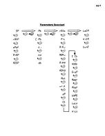
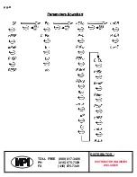
* Press and hold the SCROLL key for at least 4 seconds. The “AT” LED and/or the rightmost decimal point on the PV display is flashing during execution of
autotune program.
Autotune teaches the controller the maincharacteristics of the process. It learns by cycling the output on and off. The result are measured and used to
calculate optimums PID values which are automatically entered into nonvolatile memory.
After two oscillatory cycle of ON/OFF control. The controller performs PID control to verify the result and finally a oPoF value is obtained and entered in the
memory. To stop the autotune program. Press and hold SCROLL key again for 4 seconds. The “AT” LED and the right-most decimal point on the PV display
turn off.
AUTO/MANUAL CONTROL MODES
AUTOMATIC CONTROL
In auto mode, the controller automatically adjusts the output variable in accordance with the PID algorithm to reach and maintain the desired setpoint.
Automode is the normal of operation. It can be P, PI, PD, PID or ON/OFF control.
MANUAL CONTROL
Manual control is usually used for testing purposes and allows the user to drive the outputs manually between 0.0 to 100%. To access the manual mode,
press and hold the RETURN key for 4 seconds until either the “MA” LED or the right-most decimal point on the SV display begins flashing. The controller’s
output percent will now appear on the SV display.
For controllers with two output. The SV display will toggle between output 1 and 2. To manually adjust the controller’s outputs, use the UP and DOWN keys.
TO return to AUTO mode from MANUAL mode, press and hold the RETURN key for 4 seconds again untilthe “MA” LED and decimal point turn off. The
setpoint appears on th SV display.
RAMP AND DWELL
The controller can be configured to act either as a fixed setpoint controller or as a single ramp controller on power up. This function enables the user to set a
predetermined ramp rate to allow the process to gradually reach setpoint temperature thus producing a “soft start” function. A dwell timer is incorporated
within the controller and the alarm 1 can be configured by setting R1Fu= 8or 9 to provide either a dwell function or a soak function to be used in conjunction
with the ramp function.
RAMP FUNCTION
if ramp function is selected, the process will increase or decrease at a predetermined rate during initial power up, or with setpoint changes. The ramp rate is
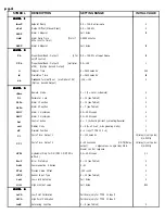
determined by rRnP parameter, which can be set in the range 0.0 to 100.0C/minute. The ramp jfunction is disabled when the rRnP parameter is set to zero.
DWELL & SOAK FUNCTION
The dwell & saok function is enabled by configuring the alarm 1 to act as a timer. If R1Fu is set to 8, the alarm 1 relay will now operate as a timer contact with
the contact being opened at power up and closed after the elapsed time set at parameter. If R 1Fu is set to 9 a reverse action of alarm 1 will perform.
CALIBRATION
WARNING!!
NEVER ENTER THIS PROCEDURE UNLESS YOU HAVE APPROPRIATE CALIBRATION EQUIPMENT. THIS PROCEDURE SHOULD BE PERFORMED BY A
TRAINED TECHNICAN.
1.
Press both scroll and return key simultaneously for 5 seconds, then release. Repeat above operation until LoCR appear on the PV display.
2.
Remove the sensor from the controller’s input terninals and connect a Thermocouple or RTD simulation signal to the controller’s input terminals. For a
process DC input, use a 4 to 20 mA or 1 to 5 VDC signal, depending on the input type of controller.
3.
Apply the low input signal to hte controller which corresponds to the range you are using i.e., for thermocouple input, 0C would be applied to the
controller.
4.
Use up and down key to adjust the SV display to match the input signal you have applied to the controller.
5.
Press and hold the return key for at least 5 seconds and the parameter on the PV display will change from LoCR to H,CA. The calibration value is
now written into the controller’s nonvolatile
memory.
6.
Apply the high input signal to the controller which correspnds to the range you are using.
7.
Use up aand down key to adjust the SV display to match the input signal you have applied to the controller.
8.
Press and hold the return key fro at least 5 seconds and the parameter on the PV display will change from H, CA to SP. The low calibratin value is
now written into the controller’s non-volatile memory.
9.
Input a signal midway between the low and high calibration signals previously applied and verify that the display matches the input siganl. Repeat the
above procedure as necessary.
pg.7


