1 0
MCDISK-E
High-Tech Made in Switzerland
1
2
50
49
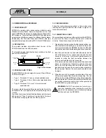
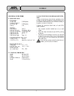
J3: SCSI
connector
J6: Power
connector
+12V
GND
+5V
2.7 POWER AND SCSI BUS CONNECTION
This chapter provides directions for connecting the SCSI bus
cable and the power cable to the MCDISK-E.
WARNING: Before you begin, review and observe
the safety precautions described at the beginning
of this manual to avoid personal injury or damage
to equipment.
2.7.1 SCSI BUS CONNECTION
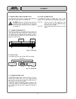
The SCSI bus connector J3 is located at the rear of the unit.
It accepts 50-pin flat ribbon cables with a standard female
connector. When connecting the SCSI bus cable to connector
J3, carefully align both connectors to avoid bending or dam-
aging the connector pins.
Fig. 2.7.1: Rear view
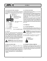
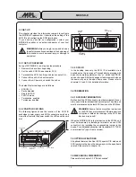
2.7.2 SCSI Chain
The following figure shows a typical SCSI connections.
2.7.3 POWER CONNECTION
The MCDISK requires a power input of +5 VDC (+/- 5% , typ.
120mA) and +12VDC (±5%, min. 1mA). When providing
power for the unit, take into account the additional current
consumption of the cards to be used!
The power connector J6 is located at the rear of the unit. This
4-pin keyed connector accepts standard connectors of vari-
ous manufacturers. The pin-out of connector J6 is shown in
Figure 2.7.1.
2.8 DC VOLTAGE MONITOR
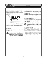
The MCDISK-E monitors the voltage level of the +5 VDC
supply. The unit resets/runs at the following voltage levels:
4.70 VDC:
In power-up, the +5 VDC supply has to rise
above this level, otherwise MCDISK-E stays
reset and will not operate.
4.45 VDC:
If the voltage drops below this level, the unit
resets.
Internal HD
MCDISK-E
SCSI Controller
ID 0
ID 1-6
ID 7
SCSI Bus
Fig. 2.7.2 SCSI chain


