7
High-Tech Made in Switzerland
MS-MCDISK-D Rev. B
MCDISK
(not terminated)
Host computer
Internal SCSI device
(terminated)
External SCSI device
(terminated)
External SCSI device
(not terminated)
2.5 TERMINATION
2.5.1 SCSI BUS TERMINATION
Both ends of the SCSI bus cable must be terminated. Gener-
ally, one end is already terminated at the host computer. The
other end must be terminated by the last SCSI device on the
SCSI bus.
WARNING: Ensure that no more than two devices
on the SCSI bus are terminated. Otherwise serious
corruption of data and/or damage to the SCSI bus
devices may result!
When the MCDISK-D is the last device on the SCSI bus, it
must be terminated by setting the termination configuration
switch to the ON position (Switch No. 2). In all other cases, this
switch must be set to the OFF position!
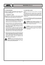
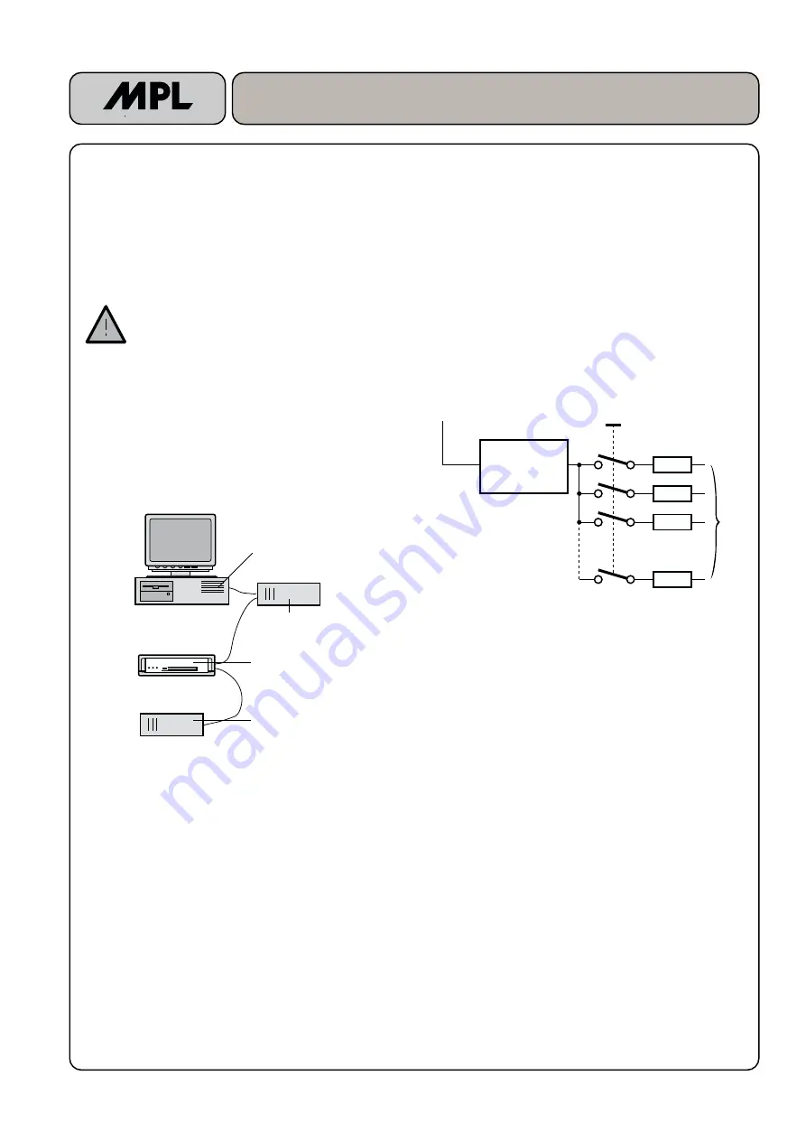
The figure below shows an SCSI chain configuration where
the MCDISK-D is in a middle position (and therefore not
terminated).
Fig. 2.5.1: SCSI bus configuration
2.5.2 TERMINATOR POWER (TERMPWR)
Generally, the host computer is the only device on the SCSI
bus required to provide TERMPWR for the bus. Since the
MCDISK-D is a peripheral SCSI device, power for the termi-
nator networks must be supplied from the SCSI bus cable
(TERMPWR line).
The MCDISK-D contains internal components to provide
switchable Active Termination of the SCSI bus. Compared to
Passive Termination, Active Termination is far less sensitive
to TERMPWR voltage variations, which, amongst other
things, increases data security.
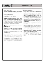
Figure 2.5.2 shows the terminator circuit as used on the
MCDISK-D:
Fig. 2.5.2: Active termination
Voltage
regulator
2.85V Output
110
Ω
110
Ω
110
Ω
110
Ω
18 SCSI - bus lines
TERMPWR
4.00 É 5.5 V
Termination
power switch
2.6. PARITY
The SCSI parity configuration of the MCDISK-D should match
that of the host computer. Check the host computer documen-
tation to verify its setting. On delivery, the MCDISK-D’s parity
is disabled (Switch No. 1 to OFF) which should be correct for
most system integrations. The parity can be enabled by
setting the parity configuration switch to the ON position.


