background image

Revision #3 (09/07/01)

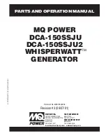
MQ POWER

 DCA-150SSJU

DCA-150SSJU2

 WHISPERWATT

TM

GENERATOR

PARTS AND OPERATION MANUAL

MULTIQUIP INC.....

PARTS DEPARTMENT:

18910 WILMINGTON AVE.

800-427-1244

CARSON, CALIFORNIA 90746 FAX:  800-672-7877
310-537-3700

SERVICE DEPARTMENT:

800-421-1244

800-835-2551

FAX: 310-537-3927

FAX: 310-638-8046

E-mail:mq@multiquip.com 

 www:multiquip.com

© COPYRIGHT 2001, MUL

TIQ

UIP INC

.

Parts List No. M3870300254

Summary of Contents for DCA-150SSJU

Page 1: ...MANUAL MULTIQUIPINC PARTS DEPARTMENT 18910 WILMINGTON AVE 800 427 1244 CARSON CALIFORNIA 90746 FAX 800 672 7877 310 537 3700 SERVICE DEPARTMENT 800 421 1244 800 835 2551 FAX 310 537 3927 FAX 310 638 8046 E mail mq multiquip com www multiquip com COPYRIGHT 2001 MULTIQUIP INC Parts List No M3870300254 ...

Page 2: ...PAGE 2 DCA 150SSJU PARTS AND OPERATION MANUAL REV 3 09 07 01 ...

Page 3: ...ODEL AND SERIAL NUMBER ON HANDWHEN CALLING PARTS DEPARTMENT 800 427 1244 or 310 537 3700 FAX 800 672 7877 or 310 637 3284 SERVICE DEPARTMENT 800 835 2551 or 310 537 3700 FAX 310 638 8046 WARRANTY DEPARTMENT 800 835 2551 or 310 537 3700 FAX 310 638 8046 MAIN 800 421 1244 or 310 537 3700 FAX 310 537 3927 ...

Page 4: ...ion 24 Major Components 26 Dimensions 27 Control Panel Descriptions 28 29 Engine Operating Panel Description Engine Controller 30 31 Engine Operating Panel Description Ignition 32 33 OutputTerminal Panel Descriptions 34 41 Installation 42 43 Pre Setup 44 47 Load Application 48 Generator Start UpW Key 49 51 Start Up Engine Controller Manual 52 53 Start Up Engine Controller Auto 54 Generator Shut Do...

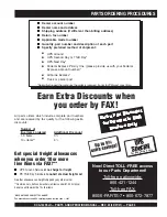
Page 5: ...of line items ordered Additional Discount 1 9 items 3 10 items 5 Now Direct TOLL FREE access to our Parts Department Toll free nationwide 800 421 1244 Toll free FAX 800 6 PARTS 7 800 672 7877 Dealer account number Dealer name and address Shipping address if different than billing address Return fax number Applicable model number Quantity part number and description of each part Specify preferred m...

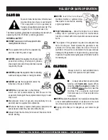
Page 6: ...nt should not be operated by persons under 18 years of age NEVERoperatethisequipment without proper protective clothing shatterproof glasses steel toed boots and other protective devices required by the job NEVERoperatethisequipmentwhennotfeeling wellduetofatigue illnessor taking medicine NEVER operate this equipment under the influence or drugs or alcohol NEVER use accessories or attachments whic...

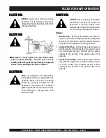
Page 7: ...icienttimefortheengineandgenerator to cool before performing maintenance Radiator 1 Radiator Cap Removing the radiator cap while the engine is hot will result in high pressurized boiling water to gush out of the radiator causing severe scalding to any persons in the general area of the generator 2 Coolant Drain Plug Removing the coolant drain plug while the engine is hot will result in hot coolant...

Page 8: ...g the generator always use the balanced center point suspension hook and lift straight upwards NEVER allow any person or animal to stand underneath the machine while lifting When loading the generator on a truck be sure to use the front and back frame bars as a means to secure the generator during transport Battery Neveroverfillthebatterywithwaterabove the upper limit CAUTION CAUTION CAUTION CAUTI...

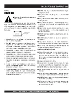
Page 9: ...andfirstaidkit Knowthelocationofthenearesttelephone Also know the phone numbers of the nearest ambulance doctor and fire department Maintenance Safety NEVER lubricate components or attempt service on a running machine Always allow the machine a proper amount of time to cool before servicing Keep the machinery in proper running condition Fix damage to the machine immediately and always replace brok...

Page 10: ... Also check the tire tread wear on both vehicles ALWAYS make sure the trailer is equipped with a Safety Chain ALWAYS attach trailer s safety chain to bumper of towing vehicle DCA 150SSJU TOWING RULES FOR SAFE OPERATION ALWAYS make sure the vehicle and trailer directional backup brake and trailer lights are connected and working properly The maximum speed for highway towing is 45 MPH unlesspostedot...

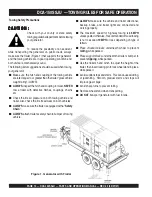
Page 11: ...TRAILER SAFETY GUIDELINES CAUTION CAUTION CAUTION CAUTION CAUTION ALWAYS make sure the trailer is in good operating condition Check the tires for proper inflation and wear Also check the wheel lug nuts for proper tightness 7 Coupler Type of hitch used on the trailer for towing 8 Tire Size Indicates the diameter of the tire in inches 10 12 14 etc and the width in millimeters 175 185 205 etc The tir...

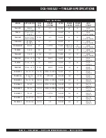
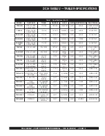
Page 12: ... 7 0 6 5 4 A C D O N E G R U S S B L 0 0 0 7 6 8 1 7 7 B L 0 0 0 2 D A P T A L F X 0 7 R L R T 0 7 0 6 5 4 A C D T P O E G R U S S B L 0 0 0 7 8 3 1 6 6 B L 0 0 0 2 D A P T A L F F X 0 7 R L R T 0 7 0 6 5 4 A C D L A G 3 5 E G R U S S B L 0 0 0 7 8 3 1 6 6 B L 0 0 0 2 D A P T A L F F X 0 0 1 R L R T 5 2 1 0 0 1 A C D L A G 0 5 1 E G R U S C I L U A R D Y H S B L 0 0 0 7 0 9 1 6 7 B L 0 0 0 2 D A P...

Page 13: ... B U R E L O P 4 T A L F X 0 7 R L R T S S A L C L L A B 2 E L B A T S U J D A 3 C 4 1 5 0 2 4 S A I B 5 X 4 1 s b l 0 0 5 3 3 G U L 5 F A E L 5 R E B B U R E L O P 4 T A L F F X 0 7 R L R T S S A L C L L A B 2 E L B A T S U J D A 3 C 4 1 5 0 2 4 S A I B 5 X 4 1 s b l 0 0 5 3 3 G U L 5 F A E L 5 R E B B U R E L O P 4 T A L F F X 0 0 1 R L R T 6 5 2 E L B A T S U J D A E Y E 3 T P O C 5 1 5 0 2 4 S...

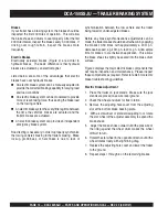
Page 14: ...aking Brake lockup grabbiness or harshness is due to lack of synchronization between the tow vehicle and the trailer being towed or under adjusted brakes Before any brake synchronizations adjustments can be made the trailer brakes should be burnished in by applying the brakes 20 30 times with approximately a 20 m p h decrease in speed e g 40 m p h to 20 m p h Allow ample time for brakes to cool be...

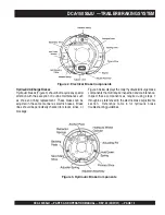
Page 15: ... adjusted in the same manner as electric brakes Brake lines should be periodically checked for cracks kinks or blockage Figure 3 below displays the major hydraulic air surge brake components that will require inspection and maintenance Inspect these components as required using steps 1 through 6 as referenced in the electric brake adjustments section Reference Table 6 for hydraulic brake troublesh...

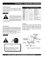
Page 16: ...actor in preservingtirelife Pressureshouldbecheckedcoldbefore operation DO NOT bleed air from tires when they are hot Check inflation pressure weekly to insure the maximum tire life and to prevent premature tread wear Table 2 Tire Wear Troubleshooting will help pinpoint the causes and solutions of tire wear problems CAUTION CAUTION CAUTION CAUTION CAUTION NOTE ALWAYSwearsafetyglasseswhenremoving o...

Page 17: ... 3 5 6 0 5 3 1 5 2 0 2 0 4 5 3 5 6 0 5 4 1 5 2 0 2 0 6 0 5 0 2 1 0 9 5 1 5 2 0 2 0 6 0 5 0 2 1 0 9 6 1 5 2 0 2 0 6 0 5 0 2 1 0 9 Lug NutTorque Requirements It is extremely important to apply and maintain proper wheel mounting torque on the trailer Be sure to use only the fasteners matched to the cone angle of the wheel Proper procedure for attachment of the wheels is as follows 1 Start all wheel l...

Page 18: ...PAGE 18 DCA 150SSJU PARTS AND OPERATION MANUAL REV 3 09 07 01 NOTE LIGHTS ARE ORIENTED FROM THE DRIVER S SEAT DCA 150SSJU TRAILERWIRING DIAGRAM ...

Page 19: ... e d i S e n O o t l l u P s g n i n i l r o s t e n g a m n o l i o r o e s a e r G e c a l p e r r o n a e l C d e d o r r o c s n o i t c e n n o C t c e r r o c d n a n a e l C n o i s o r r o c f o e s u a c d e v o o r g r o d e r o c s s m u r d e k a r B e c a l p e r r o e n i h c a M d e z i n o r h c n y s s e k a r B t c e r r o C s e k a r B g n i k c o L r o t n e b e s o o l s t n e...

Page 20: ... y l l a u q e s e r i t l l a e t a l f n I e l x a e m a s e h t n o d e h c t a m n u s e r i T s e r i t h c t a M s e k a r B g n i k c o L n e k o r b r o t n e b e s o o l s t n e n o p m o c e k a r B s t n e n o p m o c e c a l p e R d n u o r f o t u o s m u r d e k a r B e c a l p e R s e k a r B y s i o N d e t a c i r b u l m e t s y S e t a c i r b u L t c e r r o c s t n e n o p m o...

Page 21: ...nerator is equipped with a number of safety decals These decals are provided for operator safety and maintenance information The illustration below and on the preceding pages show the decals as they appear on the machine Should any of these decals become unreadable replacements can be obtained from your dealer ...

Page 22: ...PAGE 22 DCA 150SSJU PARTS AND OPERATION MANUAL REV 3 09 07 01 DCA 150SSJU GENERATOR DECALS ...

Page 23: ...e w o P C A x u A z H 0 6 e s a h P e l g n i S e g a t l o V V 0 2 1 t u p t u O 2 x W K 4 2 W K 8 4 s n o i t a c i f i c e p S e n i g n E l e d o M 1 0 0 F T 1 8 0 6 E R E E D N H O J e p y T d e g r a h c o b r u t n o i t c e j n i t c e r i d d e l o o c r e t a w e l c y c 4 s r e d n i l y C f o o N s r e d n i l y c 6 e k o r t S x e r o B m m 9 2 1 x m m 6 1 1 n i 8 0 5 x n i 7 5 4 t u ...

Page 24: ...ormance requirement for the generator Reference Table 7 page 23 for engine specifications In keeping with MQ Power s policy of constantly improving its products the specifications quoted herein are subject to change without prior notice The basic controls and indicators for the DCA 150SSJU generator are addressed on the following pages Electronic Governor System The electronic governor system is m...

Page 25: ...DCA 150SSJU PARTS AND OPERATION MANUAL REV 3 09 07 01 PAGE 25 NOTE PAGE ...

Page 26: ...PAGE 26 DCA 150SSJU PARTS AND OPERATION MANUAL REV 3 09 07 01 DCA 150SSJU ___ MAJOR COMPONENTS Figure 6 Major Components ...

Page 27: ...DCA 150SSJU PARTS AND OPERATION MANUAL REV 3 09 07 01 PAGE 27 DCA 150SSJU DIMENSIONS Figure 7 Dimensions ...

Page 28: ...PAGE 28 DCA 150SSJU PARTS AND OPERATION MANUAL REV 3 09 07 01 DCA 150SSJU CONTROL PANEL Figure 8 Control Panel ...

Page 29: ...lows the AC ammeter to indicate the current flowing to the load connected to any phase of the output terminals or to be switched off 4 Voltmeter Change Over Switch This switch allows the AC Voltmeter to indicate phase to phase voltage between any two phases of the output terminals or to be switched off 5 Voltage Regulator Control Allows adjustment of the generator s output voltage 6 Frequency Mete...

Page 30: ...PAGE 30 DCA 150SSJU PARTS AND OPERATION MANUAL REV 3 09 07 01 DCA 150SSJU ENGINE OPERATING PANEL Figure 9 Engine Operating Panel S N 7600091 ...

Page 31: ...lt will shutdown the generator if it may be damaging to the engine A Off Manual Auto Switch This switch controls the running of the generator If this switch is left in the OFF position the generator will not run When this switch is set to the manual position the generator will start immediately If the generator is to be connected to a building s AC power source via a transfer switch isolation plac...

Page 32: ...PAGE 32 DCA 150SSJU PARTS AND OPERATION MANUAL REV 3 09 07 01 DCA 150SSJU ENGINE OPERATING PANEL Figure 10 Engine Operating Panel UPTO S N760090 ...

Page 33: ...ge Indicates the current being supplied by the engine s alternator which provides current for generator s control circuits and battery charging system 6 Fuel Gauge Indicates amount of diesel fuel available 7 Tachometer Indicates engine speed in RPM s for 60 Hz operation This meter should indicate 1800 RPM s when the rated load is applied In addition a built in hour meter will record the number of ...

Page 34: ...igure 11 120Volt Receptacle Two GFCI Duplex Nema 5 20R 120V 20 Amp receptacle is provided on the output terminal This receptacle can be used anytime the generator is in operation The receptacle is controlled by the circuit breaker located on the control panel Pressing the reset button resets the receptacle after being tripped Pressing the Test Button See Figure 12 in the center of this receptacle ...

Page 35: ...DCA 150SSJU PARTS AND OPERATION MANUAL REV 3 09 07 01 PAGE 35 DCA 150SSJU OUTPUTTERMINAL PANEL OVERVIEW Legs O and Ground are considered Bonded Grounds NOTE FIGURE 14 Output Terminal Panel ...

Page 36: ...ge Selector Switch press in the red button located on the Voltage Selector Switch and use a pad lock to hold it into this position Over Current Relay An over current relay is connected to the circuit breaker In an over current situation both the circuit breaker and the over current relay may trip If the circuit breaker can not be reset the reset button on the over current relay must be pressed The...

Page 37: ...switch to the W U position and the AC ammeter Change over Switch to the U or W position to read the output on the selected leg FIGURE 15 Voltage Selector Switch 240 120V Single Phase Position FIGURE 16 AC Voltmeter Change over switch Reading the W U leg on the output terminal panel FIGURE 19 AC Ammeter Amp reading on U lug FIGURE 18 AC Ammeter Change over Switch Reading the U leg on the output ter...

Page 38: ...dWire Hookup The output terminal panel when suppling three phase 240 volts will provide one circuit available at 361 amps with any twowiresplustheground SeeFigure 23below Thevoltage selector switch must be set at the three phase 480 277V position See Figure 22 below The output terminal panel when suppling 3 phase 480 volts will provide one circuit available at 180 amps available with all three wir...

Page 39: ...416V After hooking up the hard wires to the lugs as shown in Figure 27 below 480V will be the voltage with the Voltage Regulator Knob turned toward maximum 440 volt will be reached when the Voltage Regulator Knob is turned down and 416 volt when the Voltage Regulator Knob is toward the lowest setting See Figure 25 Single Phase 277V 254V or 240V The following connection with the voltage selector sw...

Page 40: ...oking up the hard wires to the lugs as shown in Figure 32 below 240V will be the voltage with the Voltage Regulator Knob turned toward maximum 220 volt will be reached when the Voltage Regulator Knob is turned down and 208 volt when the Voltage Regulator Knob is toward the lowest setting See Figure 30 Single Phase 139V 127V or 120V The following connection with the voltage selector switch locked i...

Page 41: ...s shown in Figure 36 below use the Voltage Regulator Knob to fine tune to 240V See Figure 35 Single Phase 120 Volt The following connection with the voltage selector switch locked into the single phase 240 120V position See Figure 34 will offer SINGLE PHASE power at 120V After hooking up the hard wires to the lugs as shown in Figure 37 below use the Voltage Regulator Knob to fine tune to 120V See ...

Page 42: ...shine Make sure the generator is on secure level ground so that it cannot slide or shift around Also install the generator in a manner so that the exhaust will not be discharged in the direction of nearby homes The installation site must be relatively free from moisture and dust All electrical equipment should be protected from excessive moisture Failure to do will result in deterioration of the i...

Page 43: ...ERATION MANUAL REV 3 09 07 01 PAGE 43 Figure 38 Typical Generator Grounding Application DCA 150SSJU INSTALLATION CAUTION CAUTION CAUTION CAUTION CAUTION Always check Local State and Federal laws before grounding generator set ...

Page 44: ... the voltage drop between the generator and point of use load is held to a minimum Use the Cable Selection Guide Table 11 as a guide for selecting proper cable size Circuit Breakers To protect the generator from an overload a 3 pole 400 amp main circuit breaker is provided to protect the UVW output terminals from overload In addition two single pole 20 amp GFCI circuit breakers are provided to pro...

Page 45: ...l Dipstick When checking the engine oil be sure to check if the oil is clean and viscous If the oil is not clean drain the oil by removingtheoildrainplug andrefillwiththespecifiedamount of oil as outlined in the John Deere Engine Owner s Manual l i O r o t o M d e d n e m m o c e R 2 1 e l b a T e r u t a r e p m e T e g n a R l i O e p y T 2 2 o 8 F o F 0 5 o 5 1 C o C 0 4 w 5 1 E A S 6 8 o 2 2 F...

Page 46: ...AUTION CAUTION CAUTION CAUTION CAUTION Cleaning the Radiator The engine may overheat if the radiator fins become overloaded with dust or debris Periodically clean the radiator fins with compressed air Cleaning inside the machine is dangerous so clean only with the engine turned off and the battery disconnected Air Cleaner Periodic cleaning replacement is necessary Inspect it in accordance with the...

Page 47: ...nspect the entire generator for bad or worn electrical wiring or connections If any wiring or connections are exposed insulation missing replace wiring immediately Piping and Hose Connection Inspect all piping oil hose and fuel hose connections for wear and tightness Tighten all hose clamps and check hoses for leaks If any hose fuel or oil lines are defective replace them immediately Ether Caniste...

Page 48: ...When connecting a fluorescent or mercury lamp a capacity of up to the generating set s rated output kW multiplied by 0 6 can be used z When connecting an electric drill or other power tools pay close attention to the required starting current capacity When connecting ordinary power tools a capacity of up to the generating set s rated output kW multiplied by 0 8 can be used d a o L y B r o t c a F ...

Page 49: ... fuel immediately Before Starting Generator and Control Panel CAUTION zNEVER start the engine with the main GFCI or load circuit breakers in the ON position The engine s exhaust contains harmful emissions ALWAYS ventilate the exhaust when operating inside tunnels excavations or buildings Direct exhaust away from nearby personnel Figure 42 Main GFCI and Load Circuit Breakers DCA 150SSJU GENERATOR S...

Page 50: ...frequency in HERTZ Figure 51 Frequency Meter Hz 7 Check the engine throttle lever is in low position Figure 48 9 Let the engine warm up for a few minutes Then pull and turn the throttle lever to the right to set the engine speed to high Figure 50 Figure 52 Voltage Meter Volts 11 The generator s voltage meter Figure 52 displays the 120 VAC in VOLTS If the voltage is not within the specified frequen...

Page 51: ...d 12 The ammeter Figure 54 will indicate zero amps with no load applied When a load is applied this meter will indicate the amount of current that the load is drawing from the generator s alternator Figure 57 Engine Tachometer 13 The engine oil pressure gauge Figure 55 will indicate the oil pressure of the engine Under normal operating conditions the oil pressure is approximately 41 to 71 psi 14 T...

Page 52: ...ance Figure 65 Engine Controller Running Status LED 8 Place the Off Manual Auto switch Figure 64 in the MANUAL position The engine will start cranking 10 Let the engine warm up for a few minutes Change the idle switch to HIGH Figure 66 Figure 66 Engine Switch HIGH 11 The generator s frequency meter Figure 67 displays the 60 cycle output frequency in HERTZ Figure 67 Frequency Meter Hz 12 The genera...

Page 53: ...Under normal operating conditions the coolant temperature is approximately 215o F Figure 72 Coolant Temperature Gauge Figure 71 Oil Pressure Gauge 18 Observe the generator s ammeter Figure 75 and verify it reads the anticipated amount of current with respect to the load The ammeter will only display a current reading if the load is in use 19 The generator will run until manually stopped or an abno...

Page 54: ...in the auto mode 3 Continue to follow the steps outline in the manual start up procedure start at step 11 page 32 CAUTION When starting generator in Auto mode use the Manual Start up procedure except where noted see below 1 Perform steps 1 through 7 page 52 as outlined in the manual starting procedure 2 Place the Off Manual Auto switch Figure 74 in the AUTO position Figure 74 Off Manual Auto Switc...

Page 55: ...SSJU SHUTDOWN PROCEDURE Figure 79 Engine Controller Status LED OFF Figure 78 Off Manual Auto Switch OFF 5 Verify that the Engine Running status LED Figure 79 on the Auto On Offf Engine Controller display is OFF not lit 4 Place the Off Manual Auto Switch Figure 78 in the OFF RESET position ENGINE SHUTDOWN Engine Controller To shutdown the generator use the following procedure 1 Switch both the MAIN...

Page 56: ...nt Cleaning and Installing Ether Canister Remove safety cap from ether canister Remove spray nozzle from canister Remove the old canister assembly from the solenoid and properly dispose the old canister Install the new canister and canister assembly to the solenoid General Inspection Prior to each use the generating set should be cleaned and inspected for deficiencies Check for loose missing or da...

Page 57: ... C r e h t E e c a l p e R X t n a l o o C k c e h C d n a r o t a i d a R n a e l C l e v e L n o i t c e t o r P X t n e m e l E r e t l i F r i A e c a l p e R X r o t s i s e R n o i s o r r o C e g n a h C X s p m a l C d n a s e s o H l l a k c e h C X k n a T l e u F f o e d i s n I n a e l C X O T A R E N E G R r e v O e c n a t s i s e R n o i t a l u s n I e r u s a e M s m h o M 3 X 1 y...

Page 58: ...r o l e u f d e i f i c e p s e h t e s U e n a t e c w o l h t i w l e u F r e b m u n l e u f d e i f i c e p s e h t e s U e s o o l o t e u d k a e l l e u F t u n g n i n i a t e r e p i p n o i t c e j n i t u n n e t h g i T g n i m i t n o i t c e j n i t c e r r o c n I t s u j d A n r o w t f a h s m a c l e u F e c a l p e R d e g g o l c e l z z o n n o i t c e j n I e l z z o n n o i ...

Page 59: ...n i g n E r e w o p C A n i t n e s e r p s i e g a t l o v e c r u o s r o t o r e v i t c e f e D r o t o r e c a l p e R C A n i t n e s e r p e g a t l o v o N e c r u o s r e w o p 1 E R r e i f i t c e r e c a l p e R r e t e m t l o v e v i t c e f e D r e t e m t l o v e c a l p e R g n i r i w d e t c e n n o c s i D g n i r i w r i a p e r d n a k c e h C n i t i u c r i c t r o h s r e ...

Page 60: ...i d a r r i a p e r n a e l C n e p o s r o o D s r o o d e s o l C g n i k a e l t s u a h x E t r a p y t l u a f r o s t e k s a g r i a p e r e c a l p e R d e d a o l r e v o g n i e b r o t a r e n e G d a o l e c u d e r k c e h C e r u l i a f t a t s o m r e h T t a t s o m r e h t e c a l p e R d e k c o l b e k a t n i r i A s e k a t n i r i a l l a r a e l C e r u l i a f h c t i w s ...

Page 61: ...DCA 150SSJU PARTS AND OPERATION MANUAL REV 3 09 07 01 PAGE 61 DCA 150SSJU WIRING DIAGRAM GENERATOR ...

Page 62: ...PAGE 62 DCA 150SSJU PARTS AND OPERATION MANUAL REV 3 09 07 01 DCA 150SSJU WIRING DIAGRAM ENGINEW STARTER SWITCH ...

Page 63: ...DCA 150SSJU PARTS AND OPERATION MANUAL REV 3 09 07 01 PAGE 63 DCA 150SSJU WIRING DIAGRAM ENGINEWITH CONTROLLER ...

Page 64: ... part is used Model Number Where indicated this shows that the corresponding part is utilized only with this specific model number or model number variant Items Found In the Items Number Column All parts with same symbol in the number column or n belong to the same assembly or kit Note If more than one of the same reference number is listed the last one listed indicates newest or latest part avail...

Page 65: ...AR51481 KEY SET STARTER SWITCH 2 2 0602122281 OIL SWITCH 1 M3310500203 RADIATOR HOSE UPPER 1 M3310500303 RADIATOR HOSE LOWER 1 0605505070 FUEL CAP 1 0601820671 AUTOMATICVOLTAGE REGULATOR 1 0601808815 MAIN CIRCUIT BREAKER 1 0601808804 CIRCUIT BREAKER 1 0602103092 PILOT LAMP 2 0601810245 BULB PILOT LAMP 1 0602011068 CAP RADIATOR 1 0602122271 UNIT OIL PRESSURE 1 0602123261 UNIT WATERTEMPERATURE 1 060...

Page 66: ...PAGE 66 DCA 150SSJU PARTS AND OPERATION MANUAL REV 3 09 07 01 GENERATOR ASSY DCA 150SSJU GENERATOR ASSY ...

Page 67: ...R 4 23 031110160 PLAIN WASHER 4 REPLACES 0041210000 24 0010112035 HEX HEAD BOLT 6 25 0040012000 LOCK WASHER 6 26 031112230 PLAIN WASHER 6 REPLACES 0041212000 27 8131310104 COVER BEARING 1 28 8131312204 GASKET BEARING 1 29 8131331003 COVER END BRACKET 1 30 0105050616 HEX HEAD BOLT 10 REPLACES 0017106012 31 8101333003 COVER END BRACKET 1 32 0010106030 HEX HEAD BOLT 2 33 0040006000 LOCK WASHER 2 34 9...

Page 68: ...PAGE 68 DCA 150SSJU PARTS AND OPERATION MANUAL REV 3 09 07 01 DCA 150SSJU CONTROL BOX ASSY CONTROL BOX ASSY ...

Page 69: ...36 15 M3213500013 CONTROL BOX COVER 1 S N7600001 TO 7600036 M3213500013 CONTROL BOX COVER 1 S N7600014 16 011106015 HEX HEAD BOLT 4 REPLACES 0016906015 17 M3923100014 SELECTOR SWITCH 1 VY 200 18 M3213600203 SWITCH BRACKET 1 19 0330000370 EDGES 2 REPLACES 0330000370 20 0027104010 MACHINE SCREW 4 21 011106015 HEX HEAD BOLT 8 REPLACES 0016906015 22 M3213600304 SWITCH COVER 1 23 011106015 HEX HEAD BOL...

Page 70: ...PAGE 70 DCA 150SSJU PARTS AND OPERATION MANUAL REV 3 09 07 01 DCA 150SSJU CONTROL BOX ASSY CONTROL BOX ASSY ...

Page 71: ...ACHINE SCREW 2 S N7600001 TO 7600090 42 0602202592 STARTER RELAY 1 AT141011 43 011808015 MACHINE SCREW 2 REPLACES 0027106015 44 0602202597 RELAY 1 AL81719 45 0027105015 MACHINE SCREW 1 46 0601823240 RECTIFER 1 S N7600091 DE4503 47 DYN110754000012 CONTROLLER 1 S N7600091 REPLACES 0602202546 48 0027105015 MACHINE SCREW 1 S N7600091 49 LY2D12VD RELAY 1 S N7600091 REPLACES 0601827656 0601823109 BASE 1...

Page 72: ...PAGE 72 DCA 150SSJU PARTS AND OPERATION MANUAL REV 3 09 07 01 CONTROL BOX ASSY ENGINE RADIATOR ASSY DCA 150SSJU ENGINE AND RADIATOR ASSY S N7600091 ...

Page 73: ...11068 CAP 1 S N7600001TO 7600120 0602011066 CAP 1 S N7600121 C89C0225010 16 0602010691 SHROUD 1 S N7600001TO 7600120 R132912 0602010692 SHROUD 1 S N7600121 C2810064100 17 0602010795 FAN COVER 1 S N7600001TO7600120 C2810044210 0602010796 FAN COVER 1 S N7600121 C2810064200 18 012210025 HEX HEAD BOLT 8 REPLACES 0016910025 S N7600001TO 7600120 0343003070 HEX HEAD BOLT 5 S N7600121 0043003000 LOCKWASHE...

Page 74: ...PAGE 74 DCA 150SSJU PARTS AND OPERATION MANUAL REV 3 09 07 01 ENGINE RADIATOR ASSY DCA 150SSJU ENGINE AND RADIATOR ASSY S N7600091 ...

Page 75: ...46379 ELEMENT AIR CLEANER 1 S N7600001TO 7600141 XLP18 2035 0602046680 ELEMENT AIR CLEANER 1 S N7600142 P532966 37 0602040650 INDICATOR AIR CLEANER 1 RBX002252 38 0602040591 BAND AIR CLEANER 2 S N7600001TO 7600141 0602040555 BAND AIR CLEANER 2 S N7600142 P004079 39 011008020 HEX HEAD BOLT 4 REPLACES 0016908020 40 020108060 HEX NUT 4 REPLACES 0207008000 41 M3373100103 HOSE AIR CLEANER 1 S N7600001T...

Page 76: ...PAGE 76 DCA 150SSJU PARTS AND OPERATION MANUAL REV 3 09 07 01 ENGINE RADIATOR ASSY DCA 150SSJU ENGINE AND RADIATOR ASSY S N7600091 ...

Page 77: ...LT 1 S N7600001TO 7600090 69 0043003000 LOCKWASHER 1 S N7600001TO 7600090 70 0043103000 PLAINWASHER 1 S N7600001TO 7600090 71 0605511395 VALVE 1 S N7600091 XV500P8 72 DYNC10502000012 ACTUATOR 1 S N7600091 REPLACES 0602150095 73 M3356200203 STOPPER BRACKET 1 S N7600091 74 0016906020 HEX HEAD BOLT 2 S N7600091 75 M3356200103 ACTUATOR BRACKET 1 S N7600091 76 0343502009 CAP SCREW 4 S N7600091 00363020...

Page 78: ...PAGE 78 DCA 150SSJU PARTS AND OPERATION MANUAL REV 3 09 07 01 ENGINE OPERATING PANEL ASSY DCA 150SSJU ENGINE OPERATING PANEL ASSY S N 7600001TO S N7600090 S N 7600091 ...

Page 79: ...VERNOR ROD 1 S N7600001TO 7600090 12 M3354300304 GOVERNOR ROD 1 S N7600001TO 7600090 13 020108060 HEX NUT 2 S N7600001TO 7600090 REPLACES 0030008000 14 0602180106 BALL JOINT 2 S N7600001TO 7600090 15 020108060 HEX NUT 2 S N7600001TO 7600090 REPLACES 0030008000 16 0602180107 BALL JOINT 2 S N7600001TO 7600090 17 020108060 HEX NUT 2 S N7600001TO 7600090 REPLACES 0036508000 18 0207006000 HEX NUT 4 S N...

Page 80: ...PAGE 80 DCA 150SSJU PARTS AND OPERATION MANUAL REV 3 09 07 01 ENGINE OPERATING PANEL ASSY DCA 150SSJU ENGINE OPERATING PANEL ASSY S N 7600001TO S N7600090 S N 7600091 ...

Page 81: ... UNIT WATERTEMPERATURE 1 0202500 26 0602121080 CHARGING AMMETER 1 100158 27 0602125090 FUEL GAUGE 1 100176 28 0602103092 ALARM LAMP 2 S N7600001TO 7600090 PL 05 0601810245 BULB 2 S N7600001TO 7600090 E 10 T 10 DC18V 29 0601810141 PANEL LIGHT 1 98268 00370 30 0601831330 SWITCH PANEL LIGHT 1 90 0001 31 ECU9988N ENGINE CONTROLLER 1 S N 7600091 REPLACES 0602202546 32 0601831340 SWITCH 1 S N760091 7562...

Page 82: ...LOWING DIGITS AFTER THE PART NUMBER WHEN ORDERING ANY PAINTED PANEL TO INDICATE COLOR OF UNIT 1 ORANGE 2 WHITE 3 SPECTRUM GRAY 4 SUNBELT GREEN 5 BLACK 6 CATERPILLARYELLOW 7 CATO GOLD 8 RED THE SERIAL NUMBER MAY BE REQUIRED OUTPUT TERMINAL ASSY DCA 150SSJU OUTPUTTERMINAL ASSY ...

Page 83: ...4 REPLACES 0016906015 15 M3236400004 CABLE OUTLET COVER 1 16 M3236300004 SUPPORTER CABLE OUTLET COVER 1 17 011206020 HEX HEAD BOLT 6 REPLACES 0016906020 18 0601808803 CIRCUIT BREAKER 2 QOU 120B 1P 20A 19 0601808804 CIRCUIT BREAKER 3 QOU 250B 2P 50A 20 M1260700304 BREAKER FITTING COVER 1 21 0222100150 CUSHION RUBBER 1 22 011206020 HEX HEAD BOLT 2 REPLACES 0016906020 23 0601812597 RECEPTACLE 2 REPLA...

Page 84: ...PAGE 84 DCA 150SSJU PARTS AND OPERATION MANUAL REV 3 09 07 01 BATTERY ASSY DCA 150SSJU BATTERY ASSY ...

Page 85: ...LT SET 2 5 0040006000 LOCKWASHER 2 6 M3346900204 BATTERY CABLE 1 S N7600001TO 7600003 M3346900214 BATTERY CABLE 1 S N7600004 M3346900214 BATTERY CABLE 1 7 M3346900104 BATTERY CABLE 1 REPLACES M3346900304 8 CABLE 1 9 0013007025 HEX HEAD BOLT 1 0043007000 LOCKWASHER 1 0043107000 PLAINWASHER 1 0040516000 TOOTHEDWASHER 1 10 012210020 HEX HEAD BOLT 1 REPLACES 0017110020 0040510000 TOOTHEDWASHER 1 DCA 1...

Page 86: ...PAGE 86 DCA 150SSJU PARTS AND OPERATION MANUAL REV 3 09 07 01 MUFFLER ASSY DCA 150SSJU MUFFLER ASSY ...

Page 87: ...001TO 7600030 0602300168 MUFFLER 1 S N7600031 2 012210025 HEX HEAD BOLT 4 REPLACES 0016910025 3 M3333000503 EXHAUST PIPE 1 4 0602325066 CLAMP 1 5 M3333200104 GASKET 1 6 0017110050 HEX HEAD BOLT 4 7 M3330400804 COVER 1 8 M3330400903 BRACKET 1 9 011008020 HEX HEAD BOLT 4 REPLACES 0016908020 10 0602326062 U BOLT SET 1 DCA 150SSJU MUFFLER ASSY ...

Page 88: ...PAGE 88 DCA 150SSJU PARTS AND OPERATION MANUAL REV 3 09 07 01 FUEL TANK ASSY DCA 150SSJU FUELTANK ASSY ...

Page 89: ... RUBBER SHEET 2 7 1502025103C DRAIN JOINT 1 REPLACES M9200000003 8 M9200200004 DRAIN BOLT 1 9 0150000018 O RING 1 10 011206020 HEX HEAD BOLT 2 REPLACES 0016906020 11 M1363400104 DRAIN HOSE 1 12 0605515198 HOSE BAND 2 13 0602042420 FUEL FILTER 1 PTG15P 14 0605512195 HOSE JOINT 1 S N760001TO 7600036 14 0602022793 HOSE JOINT 1 S N7600037 15 0602042601 LEAK OFF LINE 1 67050 16 0191300100 SUCTION HOSE ...

Page 90: ...URE ASSY DCA 150SSJU ENCLOSURE ASSY ADD THE FOLLOWING DIGITS AFTER THE PART NUMBER WHEN ORDERING ANY PAINTED PANEL TO INDICATE COLOR OF UNIT 1 ORANGE 2 WHITE 3 SPECTRUM GRAY 4 SUNBELT GREEN 5 BLACK 6 CATERPILLARYELLOW 7 CATO GOLD 8 RED THE SERIAL NUMBER MAY BE REQUIRED ...

Page 91: ...14260 PLAINWASHER 24 REPLACES 0041214000 10 M3443000402 REAR FRAME 1 S N7600001TO 7600090 M3443000412 REAR FRAME 1 S N7600091 M3493301504 ACOUSTIC SHEET 1 11 012210025 HEX HEAD BOLT 4 REPLACES 0016910025 12 M3443300603 REAR COVER 1 M3493302204 ACOUSTIC SHEET 2 13 M3443300503 DUCT REAR COVER 2 M3493301804 ACOUSTIC SHEET 1 14 0207006000 HEX NUT 12 15 011008020 HEX HEAD BOLT 12 REPLACES 0016908020 16...

Page 92: ...E FOLLOWING DIGITS AFTER THE PART NUMBER WHEN ORDERING ANY PAINTED PANEL TO INDICATE COLOR OF UNIT 1 ORANGE 2 WHITE 3 SPECTRUM GRAY 4 SUNBELT GREEN 5 BLACK 6 CATERPILLARYELLOW 7 CATO GOLD 8 RED THE SERIAL NUMBER MAY BE REQUIRED ENCLOSURE ASSY DCA 150SSJU ENCLOSURE ASSY ...

Page 93: ...EAD BOLT 2 REPLACES 0016910025 34 M3453001103 SIDE DOOR 1 M3493403804 ACOUSTIC SHEET 1 35 M3453001003 SIDE DOOR 1 M3493404404 ACOUSTIC SHEET 1 36 M3453000903 SIDE DOOR 1 M3493405204 ACOUSTIC SHEET 1 37 M3453000803 SIDE DOOR 1 M3493405304 ACOUSTIC SHEET 1 38 M3453000803 DUCT 1 M3493406303 ACOUSTIC SHEET 1 39 M3453300603 DUCT 1 M3493404804 ACOUSTIC SHEET 1 40 M3453300203 DUCT 1 M3493407003 ACOUSTIC ...

Page 94: ...PAGE 94 DCA 150SSJU PARTS AND OPERATION MANUAL REV 3 09 07 01 RUBBER SEALS ASSY DCA 150SSJU RUBBER SEAL ASSY ...

Page 95: ...AL 2 4 0228901090 RUBBER SEAL 4 5 0228900520 RUBBER SEAL 2 6 0229201200 RUBBER SEAL 4 7 0229201140 RUBBER SEAL 1 8 0228801070 RUBBER SEAL 2 9 0228800680 RUBBER SEAL 1 10 0228800640 RUBBER SEAL 1 11 0228100665 RUBBER SEAL 1 12 0228100370 RUBBER SEAL 1 13 0228100300 RUBBER SEAL 1 14 0228100365 RUBBER SEAL 1 15 0228100280 RUBBER SEAL 1 16 0228100070 RUBBER SEAL 1 DCA 150SSJU RUBBER SEAL ASSY ...

Page 96: ...PAGE 96 DCA 150SSJU PARTS AND OPERATION MANUAL REV 3 09 07 01 NAME PLATE ASSY DCA 150SSJU OPERATION AND SAFETY DECAL ASSY ...

Page 97: ...90320000 18 M9510100004 DECAL WARNING HOT PARTS 1 M91010000 19 M9510200002 DECAL MQ 1 M91020000 20 M9520000004 DECAL GROUND 1 M92000000 21 M9520000104 DECAL AMMETER CHANGE OVER SWITCH 1 M92000010 22 M9520000204 DECAL VOLTMETER CHANGE OVER SWITCH 1 M92000020 23 M9520100004 DECAL WARNING ELECTRICAL SHOCK 2 M92010000 24 M9520100204 DECAL CAUTION STOP ENGINE 1 M92010020A 25 M9520100304 DECAL SAFETY IN...

Page 98: ... be liable here under for damagesinexcessofthepurchasepriceofthe item with respect to which damages are claimed and in no event shall Multiquip be liable for loss of profit or good will or for any other special consequential or incidental damages LIMITATIONOFWARRANTIES Nowarranties expressorimplied aremade in connection with the sale of parts or trade accessories nor as to any engine not manufactu...

Page 99: ...DCA 150SSJU PARTS AND OPERATION MANUAL REV 3 09 07 01 PAGE 99 NOTE PAGE ...

Page 100: ...551 or 310 537 3700 FAX 310 638 8046 WARRANTY DEPARTMENT 800 835 2551 or 310 537 3700 FAX 310 638 8046 MAIN 800 421 1244 or 310 537 3700 FAX 310 537 3927 MULTIQUIPINC PARTS DEPARTMENT 18910 WILMINGTON AVE 800 427 1244 CARSON CALIFORNIA 90746 FAX 800 672 7877 310 537 3700 SERVICE DEPARTMENT 800 421 1244 800 835 2551 FAX 310 537 3927 FAX 310 638 8046 E mail mq multiquip com www multiquip com ...

Reviews: