background image

DCA-180SSJU — OPERATION AND PARTS MANUAL — REV. #3  (02/01/10) — PAGE 17

1

Outdoor Installation

Install the generator in a area that is free of debris,
bystanders, and overhead obstructions. Make sure the
generator is on secure level ground so that it cannot slide or
shift around. Also install the generator in a manner so that
the exhaust will not be discharged in the direction of nearby
homes.

The installation site must be relatively free from moisture
and dust. All electrical equipment should be protected from
excessive moisture. Failure to do will result in deterioration
of the insulation and will result in short circuits and grounding.

Foreign materials such as dust, sand, lint and abrasive
materials have a tendency to cause excessive wear to
engine and alternator parts.

Generator Grounding

To guard against electrical shock and possible damage to
the equipment, it is important to provide a good 

EARTH

ground.

Article 250 (Grounding) of the National Electrical Code (NEC)
provides guide lines for proper grounding and specifies that
the cable ground shall be connected to the grounding system
of the building as close to the point of cable entry as practical.

NEC articles 250-64(b) and  250-66 set the following
grounding requirements:

1. Use one of the following wire types to connect the

generator to earth ground.

a. Copper - 10 AWG (5.3 mm

2

) or larger.

b. Aluminum - 8 AWG (8.4 mm

2

) or larger.

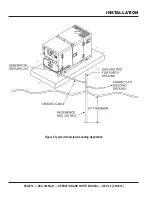
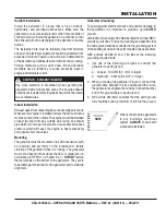
2. When grounding the generator (Figure 4) connect the

ground cable  between the lock washer and the nut on
the generator and tighten the nut fully. Connect the other
end of the ground cable to earth ground.

3. NEC article 250-52(c) specifies that the earth ground

rod should be buried a minimum of 8 ft. into the ground.

When connecting the generator
to any buildings electrical
system 

 ALWAYS

 consult with

a licensed electrician.

INSTALLATION

NOTE

Indoor Installation

Exhaust gases from diesel engines are extremely poisonous.
Whenever an engine is installed indoors the exhaust fumes
must be vented to the outside. The engine should be installed
at least two feet from any outside wall. Using an exhaust
pipe which is too long or too small can cause excessive back
pressure which will cause the engine to heat excessively
and possibly burn the valves.

Mounting

The generator must be mounted on a solid foundation (such
as concrete) and set firmly on the foundation to isolate
vibration of the generator when it is running.  The generator
must set at least 6 inches above the floor or grade level (in
accordance to NFPA 110, Chapter 5-4.1).  

DO NOT 

remove

the metal skids on the bottom of the generator.  They are to
resist damage to the bottom of the generator and to maintain
alignment.

Pay close attention to ventilation when operating the
generator inside tunnels and caves. The engine exhaust
contains noxious elements. Engine exhaust must be routed
to a ventilated area.

CAUTION - EXHAUST HAZARD

Summary of Contents for DCA180SSJU WHISPERWATT SERIES

Page 1: ...N AND PARTS MANUAL To find the latest revision of this publication visit our website at www mqpower com WHISPERWATTTM SERIES MODEL DCA180SSJU 60HZ GENERATOR JOHN DEERE 6068HF485 DIESEL ENGINE Revision 3 02 01 10 PARTS LIST NO M3870301004 ...

Page 2: ...PAGE 2 DCA 180SSJU OPERATION AND PARTS MANUAL REV 3 02 01 10 PROPOSITION 65 WARNING ...

Page 3: ...lar complaints it may open an investigation and if it finds that a safety defect exists in a group of vehicles it may order a recall and remedy campaign However NHTSA cannot become involved in individual problems between you your dealer or Multiquip To contact NHTSA you may either call the Vehicle Safety Hotline toll free at 1 888 327 4236 TTY 1 800 424 9153 go to http www nhtsa dot gov or write to...

Page 4: ...ion 43 Generator Outputs 44 45 Gauge Reading 45 Output Terminal Panel Connections 46 47 Setup 48 51 Generator Start Up Procedure Manual 52 54 Generator Start Up Procedure Auto Mode 55 Generator Shut Down Procedures 56 Maintenance Engine 57 58 Maintenance Heater Charger 59 Maintenance Trailer 60 63 Trailer Wiring Diagram 64 Generator Wiring Diagram 65 Engine Wiring Diagram 66 Troubleshooting Genera...

Page 5: ...bsite N View Parts Diagrams N Order Parts N Print Specification Information Note Discounts Are Subject To Change Goto www multiquip com and click on Order Parts to log in and save Use the internet and qualify for a 5 Discount on Standard orders for all orders which include complete part numbers Order via Fax Dealers Only All customers are welcome to order parts via Fax Domestic US Customers dial 1...

Page 6: ...W x 2 Weight No Fuel 6 571 lbs 2 980 kg Weight With Fuel 7 489 lbs 3 400 kg Engine Specifications Model JOHN DEERE 6068HF485 Type 4 Cycle water cooled direct injection turbo charged air to air intercooled No of Cylinders 6 cylinders Bore x Stroke 4 17 in x 5 in 106 mm x 127 mm Rated Output 286 HP 1800 rpm Displacement 415 cu in 6 8 liters Starting Electric Fuel Tank Capacity 100 gal 380 liters Coo...

Page 7: ... D 3 E L B A T e c n e r e f e R r e t t e L m m t f n o i s n e m i D r e t t e L e c n e r e f e R m m t f n o i s n e m i D A m m 0 4 9 n i 0 0 7 3 F m m 0 0 5 3 n i 0 8 7 3 1 B m m 0 4 9 n i 0 0 7 3 G m m 0 0 7 1 n i 0 0 7 6 C m m 0 5 0 1 n i 3 3 1 4 H m m 0 4 2 1 n i 0 8 8 4 D m m 0 5 0 1 n i 3 3 1 4 E m m 0 5 0 1 n i 3 3 1 4 ...

Page 8: ...OUSLY injured if you do not follow directions You COULD be KILLED or SERIOUSLY injured if you do not follow directions You CAN be injured if you do not follow directions Gasoline engine exhaust gases contain poisonous carbon monoxide This gas is colorless and odorless and can cause if inhaled NEVER operate this equipment in a confined area or enclosed structure that does not provide ample free flo...

Page 9: ...t This generator other property or the surrounding environment could be damaged if you do not follow instructions NOTE NEVER tamper with the factory settings of the engine governor or settings Personal injury and damage to the engine or equipment can result if operating in speed ranges above maximum allowable CAUTION OVER SPEED CONDITIONS CAUTION ACCIDENTAL STARTING CAUTION RESPIRATORY HAZARDS CAU...

Page 10: ...fold muffler or cylinder Allow these parts to cool before servicing engine or generator HighTemperatures Allow the engine to cool before performing service and maintenance functions Contact with components can cause serious burns The engine of this generator requires an adequate free flow of cooling air operate the generator in any enclosed or narrow area where free flow of the air is restricted I...

Page 11: ... damage to the equipment it is important to provide a good EARTH ground Article 250 Grounding of the NEC providesguidelinesforpropergroundingandspecifies that the cable ground shall be connected to the grounding system of the building as close to the point of cable entry as practical The following safety recommendations should also be followed ALWAYS make sure generator is properly grounded NEVER ...

Page 12: ...o gush out of the radiator causing severe scalding to any persons in the general area of the generator Coolant Drain Plug Removing the coolant drain plug while the engine is hot will result in hot coolant gushing out of the coolant drain plug therefore causing severe scalding to any persons in the general area of the generator Engine Oil Drain Plug Removing the engine oil drain plug while the engi...

Page 13: ...locks underneath the trailer s bumper to prevent tipping while parked Avoid sharp turns to prevent rolling DO NOT transport generator with fuel in tank Towing Transporting Safety To reduce the possibility of an accident while transporting the generator on public roads always make sure the trailer that supports the generator and the towing vehicle are in good operating condition and both units are ...

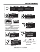
Page 14: ...y decals Figures 2 3 These decals are provided for operator safety and maintenance information The illustration below and on the preceding page show the decals as they appear on the machine Should any of these decals become unreadable replacements can be obtained from your dealer GENERATOR DECALS Figure 2 Generator Decals ...

Page 15: ...DCA 180SSJU OPERATION AND PARTS MANUAL REV 3 02 01 10 PAGE 15 1 GENERATOR DECALS Figure 3 Generator Decals Cont inued ...

Page 16: ...PAGE 16 DCA 180SSJU OPERATION AND PARTS MANUAL REV 3 02 01 10 Figure 4 Typical Generator Grounding Application INSTALLATION ...

Page 17: ...m2 or larger b Aluminum 8 AWG 8 4 mm2 or larger 2 When grounding the generator Figure 4 connect the ground cable between the lock washer and the nut on the generator and tighten the nut fully Connect the other end of the ground cable to earth ground 3 NEC article 250 52 c specifies that the earth ground rod should be buried a minimum of 8 ft into the ground When connecting the generator to any bui...

Page 18: ...ed from these windings The open delta design provides virtually unlimited excitation current offering maximum motor starting capabilities The excitation does not have a and responds according the demands of the required load Engine The DCA 180SSJUis powered by a 6 cylinder water cooled direct injection turbocharged This engine is designed to meet every performance requirement for the generator Ref...

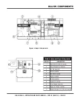
Page 19: ... e T t u p t u O 2 y l b m e s s A s e l c a t p e c e R t u p t u O 3 y l b m e s s A r e t l i F r i A 4 y l b m e s s A r e l f f u M 5 y l b m e s s A k n a T l e u F 6 y l b m e s s A e n i g n E 7 y l b m e s s A y r e t t a B 8 y l b m e s s A r o t a r e n e G 9 y l b m e s s A r e k a e r B t i u c r i C 0 1 y l b m e s s A y a l p s i D c i t s o n g a i D 1 1 y l b m e s s A l e n a P l...

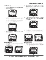
Page 20: ... and functions of the Figure 6 1 Menu Button Press this button to enter or exit menu screens 2 Left Arrow Button Press this button to scroll through the screen either moving the parameter selection toward the left or upward Figure 6 Diagnostic Display Panel 3 RightArrowButton Pressthisbuttontoscrollthrough the screen either moving the parameter selection toward the right or downward 4 Enter Key Bu...

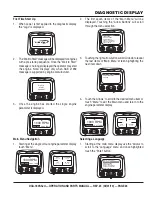
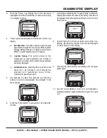
Page 21: ...displayed Touching the Arrow Buttons will scroll through the menu selection 3 Touching the right arrow button will scroll down to reveal the last items of Main Menu screen highlighting the next item down 4 Touch the Arrows to scroll to the desired menu item or touch Menu to exit the Main menu and return to the engine parameter display GO TO 1 UP DISPLAY LANGUAGES STORED CODES ENGINE CONF SETUP 1 U...

Page 22: ... ENG RPM OIL PRES GO TO 1 UP DISPLAY G ADJUST BACKLIGHT ENGINE CONF SETUP 1 UP DISPLAY SETUP 4 UP DISPLAY SELECT UNITS STORED CODES 4 If the word MORE appears above the Arrow Buttons there are more stored fault codes that may be viewed Use the Arrow Buttons to scroll to the next Stored Diagnostic Code 5 Touch the Menu Button to return to the main menu 6 Touch the Menu Button to exit the Main menu ...

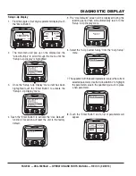
Page 23: ...displayed Touching the Arrow Buttons will scroll through the menu selection 3 Touching the right arrow button will scroll down to reveal the last items of Main Menu screen highlighting the next item down 4 Touch the Arrows to scroll to the desired menu item or touch Menu to exit the Main menu and return to the engine parameter display GO TO 1 UP DISPLAY LANGUAGES STORED CODES ENGINE CONF SETUP 1 U...

Page 24: ... ENG RPM OIL PRES GO TO 1 UP DISPLAY G ADJUST BACKLIGHT ENGINE CONF SETUP 1 UP DISPLAY SETUP 4 UP DISPLAY SELECT UNITS STORED CODES 4 If the word MORE appears above the Arrow Buttons there are more stored fault codes that may be viewed Use the Arrow Buttons to scroll to the next Stored Diagnostic Code 5 Touch the Menu Button to return to the main menu 6 Touch the Menu Button to exit the Main menu ...

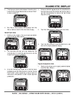
Page 25: ...erView via a daisy chained RS 485 port If at any time during system initialization or normal operation an auxiliary gage should fail the single or four parameter screen will be replaced with the MLink Gage Fault message 3 To acknowledge and Hide the fault and return to the single or four parameter display touch the Enter Button 4 The display will return to the single or four parameter screen GO TO...

Page 26: ...PM OIL PRES 98 14 2 57 PSI 1000 RPM LOAD RPM BATT VOLT ENG RPM OIL PRES SPN110 FMI10 HIGH COOLANT TEMP WARNING 1 of x MORE HIDE SPN110 FMI10 HIGH COOLANT TEMP 1 of x MORE HIDE 4 To acknowledge and Hide the fault and return to the singleorfourparameterdisplaytouchthe EnterButton 5 The display will return to the single or four parameter display but the display will contain the Active Fault warning i...

Page 27: ...1800 RPM 0 1500 3000 TEMP ENG RPM 98 14 2 57 PSI 1000 RPM LOAD RPM BATT VOLT ENG RPM OIL PRES 5 Touching the Enter Button once again will hide the fault and return the screen to the single or four parameter display 6 The Single or Four parameter screen will display the fault icon until the fault condition is corrected NOTE Ignoring active fault codes could result in severe engine damage SPN110 FMI...

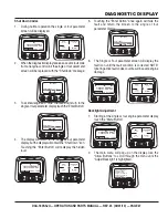
Page 28: ...ted touch the Enter Button to activate the Adjust Contrast function 4 Use the Arrow Buttons to select the desired contrast intensity 5 Touching the Menu Button will take you back through the menus GO TO 1 UP DISPLAY STORED CODES G ENGINE CONF SETUP 1 UP DISPLAY SETUP 4 UP DISPLAY SELECT UNITS ADJUST BACKLIGHT ADJUST BACKLIGHT ADJUST BACKLIGHT GO TO 1 UP DISPLAY ENGINE CONF SETUP 1 UP DISPLAY SETUP...

Page 29: ...isplay touch the Menu Button COOL 1800 RPM 0 1500 3000 TEMP ENG RPM 98 14 2 57 PSI 1000 RPM LOAD RPM BATT VOLT ENG RPM OIL PRES GO TO 1 UP DISPLAY STORED CODES G ADJUST BACKLIGHT ENGINE CONF SETUP 1 UP DISPLAY SETUP 4 UP DISPLAY SELECT UNITS GO TO 1 UP DISPLAY STORED CODES G ADJUST BACKLIGHT ENGINE CONF SETUP 1 UP DISPLAY SETUP 4 UP DISPLAY SELECT UNITS ENGLISH ESPANOL FRANCAIS DEUTSCH ENGLISH MET...

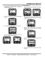
Page 30: ...nter Button to activate the Use Defaults function GO TO 1 UP DISPLAY STORED CODES G ADJUST BACKLIGHT ENGINE CONF SETUP 4 UP DISPLAY SELECT UNITS SETUP 1 UP DISPLAY USE DEFAULTS CUSTOM SETUP AUTOMATIC SCAN OFF USE DEFAULTS CUSTOM SETUP AUTOMATIC SCAN OFF 7 A message indicating the Single Engine parameter display parameters are reset to the factory defaults will be displayed then the display will re...

Page 31: ...ic Scan function on 17 Touchingthe EnterButton againtogglesthe Automatic Scan function off 18 Once the Use Defaults Custom Setup and Automatic Scan functions have been set touch the Menu Button to return to the main menu 19 Touch the Menu Button to exit the Main menu and return to the engine parameter display ENGINE SPEED PERCENT LOAD AT CURRENT RPM ENGINE OIL PRESSURE ENGINE COOLANT TEMPERATURE 1...

Page 32: ... UP DISPLAY STORED CODES ENGINE CONFG ADJUST BACKLIGHT SETUP 1 UP DISPLAY SELECT UNITS SETUP 4 UP DISPLAY GO TO 1 UP DISPLAY STORED CODES ENGINE CONFG ADJUST BACKLIGHT SETUP 1 UP DISPLAY SELECT UNITS SETUP 4 UP DISPLAY 5 The Use Defaults screen will be displayed during the resetting period then will automatically return to the Setup 4 Up Display menu 6 Select the 4 Up Custom Setup from the 4 Up Se...

Page 33: ...TEMPERATURE BATTERY POTENTIAL ENGINE OIL PRESSURE ENGINE HOURS ENGINE OIL TEMPERATURE 3 1 4 2 The number to the right of the parameter indicates the quadrant in which it is displayed 1 Upper Left Quadrant 2 Lower Left Quadrant 3 Upper Right Quadrant 4 Lower Right Quadrant ENGINE SPEED ENGINE COOLANT TEMPERATURE BATTERY POTENTIAL ENGINE OIL PRESSURE ENGINE HOURS ENGINE OIL TEMPERATURE 3 1 2 4 ENGIN...

Page 34: ...oftware version currently in the diagnostic display 9 Touch Menu to return to Utilities Highlight Fault Conversion using the Arrows Touch Select to enter the Fault conversion menu 10 Use the Arrows to scroll to and highlight the desired version then touch Select An asterisk denotes which version is currently selected NOTE There are four 4 different methods for converting fault codes The diagnostic...

Page 35: ...r and slave 5 Use the Arrows to scroll to the Serial Port menu to highlight it then touch Enter 6 Use the Arrow button to scroll to each selection to configure the MODBUS values for your application 7 When finished touch Menu to return to the previous screen ENGINE CONF SETUP 4 UP DISPLAY SELECT UNITS STORED CODES G SETUP 1 UP DISPLAY ADJUST BACKLIGHT UTILITIES COOL 1800 RPM 0 1500 3000 TEMP ENG R...

Page 36: ...message is not supported DATA ERROR Diagnostic Display has received an error message from the ECU for the displayed message EMPTY No parameter selected for this 4 UP quadrant WAIT TO START PREHEATING This is a message from the engine indicating it is in a preheating cycle Wait until this message clears before starting the engine TIMEOUT ECU NOT RESPONDING The ECU did not respond to the PowerView r...

Page 37: ...e 6 Voltmeter Change Over Switch This switch allows the AC voltmeter to indicate phase to phase voltage between any two phases of the output terminals or to be switched off 7 Main Circuit Breaker This three pole 500A main breaker is provided to protect the the from overload Located behind the generator control panel is the This box contains some of the necessary electronic components required to m...

Page 38: ...e oil pressure should return to the correct pressure range 4 WaterTemperature Gauge During normal operation this gauge be should read between 180 and 230 F 82 C and 110 C 5 Charging Ammeter Gauge Indicates the current being supplied by the engine s alternator which provides current for generator s control circuits and battery charging system 6 Fuel Gauge Indicates amount of diesel fuel available 7...

Page 39: ...resistive values from the oil pressure sending unit This is considered a fault C High Coolant Temperature Indicates the engine temperature has exceeded 239 F The engine temperature is detected using variable resistive values from the temperature sending unit This is considered a fault D Overcrank Shutdown Indicates the unit has attempted to start a pre programmed number of times and has failed to ...

Page 40: ...o 2 100V GFCI receptacles 20 amp Two 2 GFCI Circuit Breakers 20 amps Five 5 Output Terminal Lugs U V W O Ground OutputTerminal Panel The Figure 9 shown below is located on the right hand side left from control panel of the generator Lift up on the cover to gain access to receptacles and terminal lugs NOTE Terminal legs O and Ground are considered Figure 9 Output Terminal Panel OUTPUT TERMINAL PANE...

Page 41: ...he GFCI receptacles Remember the load output current on all three receptacles is dependent on the load requirements of the Turn the Figure 12 on the control panel to obtain the desired voltage Turning the knob clockwise will the voltage turning the knob counter clockwise will the voltage Figure 11 240 139V Twist Lock Auxiliary Receptacles OUTPUT TERMINAL PANEL FAMILIARIZATION Twist Lock Dual Volta...

Page 42: ...ls from overload a 3 pole 500A circuit breaker is provided Make sure to switch ALL circuit breakers to the OFF position prior to starting the engine OUTPUT TERMINAL PANEL FAMILIARIZATION Over Current Relay An Figure 15 is connected to the main circuit breaker In the event of an overload both the circuit breaker and the over current relay may trip If the circuit breaker can not be reset the on the ...

Page 43: ...o the required starting current capacity NOTE WATTS VOLTAGE x AMPERAGE Three Phase Load When calculating the power requirements for 3 phase power use the following equation NOTE An inadequate size connecting cable which cannot carry the required load can cause a voltage drop which can burn out the appliance or tool and overheat the cable See Table 6 NOTE Before connecting this generator to any bui...

Page 44: ... Figure 16 is located on the control box behind the generator control panel This board has been provided for ease of voltage selection CAUTION CHANGING VOLTAGES NEVER attempt to place jumper plates on the while the generator is in operation There exist the possibility of Figure 16 Voltage Change Over Board e l b a l i a v A s e g a t l o V 7 e l b a T e s a h P e e r h T e l b a t c e l e S V 8 0 ...

Page 45: ...V operation Figure 18 AC Voltmeter Change Over Switch Figure 19 AC Voltmeter Gauge Volt reading on W U Lug Figure 21 AC Ammeter Amp reading on U lug Figure 20 AC Ammeter Change Over Switch The gauge will only show a reading when the are connected to a load and in use NOTE GENERATOR OUTPUTS GAUGE READING Figure 17 Change Over Board 3Ø 240V Configuration AC Voltmeter Gauge Reading Place the Figure 1...

Page 46: ...ltages 1 Jumper the voltage change over board for 240V operation as shown in Figure 22 Figure 23 UVWOTerminal Lugs 3Ø 240V Connections 2 Connect the load wires to the UVWO terminals as shown in Figure 23 3 Turn the voltage regulator knob Figure 24 clockwise to increase voltage output turn counterclockwise to decrease voltage output Use voltage regulator adjustment knob whenever fine tuning of the ...

Page 47: ...ator knob Figure 24 clockwise to increase voltage output turn counterclockwise to decrease voltage output Figure 30 UWVO OutputTerminal Lugs 1Ø 277V Connections 3Ø 480 UVWO OutputTerminal Voltages 1 Jumper the voltage change over board for 480V operation as shown in Figure 27 This configuration uses 6 jumper plates in 3 different positions Remember there are 2 jumper plates at every position Every...

Page 48: ...with lubricating oil through the filler hole but DO NOT overfill Make sure the generator is level and verify that the oil level is maintained between the two notches Figure 31 on the dipstick See Table 9 for proper selection of engine oil Figure 32 Internal Fuel Tank System Refilling the Fuel System Fuel Check This generator has an internal fuel tank located inside the trailerframeandmayalsobeequi...

Page 49: ...igure 35 Full FuelTank Figure 36 Fuel Expansion 3 Open cabinet doors on the right side of the generator from generator control panel position Remove fuel cap and fill tank Figure 34 Figure 34 Fueling the Generator place trailer on firm level ground before refueling to prevent spilling and maximize the amount of fuel that can be pumped into the tank CAUTION REFUELINGTHE GENERATOR Diesel fuel and it...

Page 50: ...ute to overheating or to insufficient charging of the battery Inspect the fan belt for damage and wear and adjust it in accordance with the John Deere Engine Owner s Manual The fan belt tension is proper if the fan belt bends 10 to 15 mm Figure 37 when depressed with the thumb as shown below Figure 37 Fan Belt Tension SETUP If adding coolant antifreeze mix to the radiator DO NOT remove the radiato...

Page 51: ...ness Tighten all hose clamps and check hoses for leaks If any hose or lines are defective replace them immediately If the battery cable is connected incorrectly electricaldamagetothe generator will occur Pay close attentiontothepolarityofthebattery when connecting the battery NOTE Battery This unit is of negative ground DO NOT connect in reverse Always maintain battery fluid level between the spec...

Page 52: ...ess to the terminals Tighten terminal nuts securely to prevent load wires from slipping out 6 Close all engine enclosure doors Figure 41 CAUTION LETHAL EXHAUST HAZARD 2 Place the in the MANUAL position to start the engine Figure 43 Observe that the Warning and Emergency Stop lamps on the Engine Operating Panel are lit during the initial starting of the engine If no abnormal conditions exists both ...

Page 53: ...tion Figure 44 Active Fault Code Message 6 In a situation where several engine problems occur simultaneously the word MORE appears above the arrow buttons indicating that there are more fault codes that need to be viewed Use the arrow buttons to scroll to the next active fault code If desired the type of fault code cause of error and the countermeasures of the error can be referenced in a separate...

Page 54: ...anticipated amount of current with respect to the load The ammeter will only display a current reading if a load is in use Figure 55 Ammeter Load 20 The generator will run until manually stopped or an abnormal condition occurs GENERATOR START UP PROCEDURE MANUAL Figure 49 Voltage Adjust Control Knob Figure 50 Ammeter No Load 14 The ammeter Figure 50 will indicate with no load applied When a load i...

Page 55: ...any maintenance when the generator is in the auto mode WARNING AUTO MODE MAINTENANCE GENERATOR START UP PROCEDURE AUTO MODE WhentheMPEC is placed in the AUTO position the engine glow plugs will be warmed and the engine will start automatically NOTE When starting generator in AUTO mode use the Start up procedure except where noted see below CAUTION ENGINE SPEED SWITCH The must be set to the High po...

Page 56: ...d during operation GENERATOR SHUT DOWN PROCEDURES 3 Let the engine cool by running it at low speed for 3 5 minutes with no load applied 4 Place the Figure 59 to the OFF RESET position Figure 58 Engine Speed Switch Low NEVER stop the engine suddenly except in an emergency WARNING SHUTTING DOWNTHE GENERATOR ALWAYS make sure the diagnostic switch is placed in the OFF position before attempting to shu...

Page 57: ...spray of compressed air Replace the air cleaner as needed Air Cleaner with Dust Indicator This indicator is attached to the air cleaner When the air cleaner element is clogged air intake restriction becomes greater and the dust indicator signal shows RED meaning the element needs changing or service After changing the air element press the dust indicator button to reset the indicator TABLE 12 INSP...

Page 58: ...fuel or after disassembling the fuel system bleed the system according to the following procedure See the for details To restart after running out of fuel turn the switch to the ON position for 15 30 seconds Try again if needed This unit is equipped with an automatic air bleeding system Check Oil Level Check the crankcase oil level prior to each use or when the fuel tank is filled Insufficient oil...

Page 59: ...mmercial power has been supplied to them Figure 60 To apply commercial power to these receptacles a power cord of adequate size will be required See Table 6 When using the generator in climates there is no reason to apply power to jacket water heater However if the generator will be used in climates it is always a good idea to apply power to the jacket water heater at all times To apply power to t...

Page 60: ...o the brake lights and turn signals can be connected to the towing vehicle 16 Application Indicates which units can be employed on a particular trailer Trailer Maintenance This section is intended to provide the user with generic trailer service and maintenance information The service and maintenance guidelines referenced in this section refer to a wide range of trailers Remember periodic inspecti...

Page 61: ...rotate the star wheel in the opposite direction until the wheel rotates freely with slight lining drag 7 Replace the adjusting hole cover and lower the trailer to the ground 8 Repeat steps 1 through 7 on the remaining brakes Actuator Hydraulic surge braking requires the installation of an actuator at the tongue of the trailer Remember the or of the trailer toward the tow vehicle automatically sync...

Page 62: ...sive wear elongation of bolt holes and loosening of fasteners Replace all damaged parts suspension immediately Torqued suspension components as detailed in Table 15 Figure 62 Major Suspension Components MAINTENANCE TRAILER DO NOT attempt to repair or modify a wheel DO NOT install in inner tube to correct a leak through the rim If the rimiscracked theairpressureintheinner tube may cause pieces of t...

Page 63: ...he wheel Proper procedure for attachment of the wheels is as follows 1 Start all wheel lug nuts by hand 2 Torque all lug nuts in sequence see Figure 63 DO NOT torque the wheel lug nuts all the way down Tighten each lug nut in 3 separate passes as defined by Table 16 3 After first road use retorque all lug nuts in sequence Check all wheel lug nuts periodically Table 16 Tire Torque Requirements Whee...

Page 64: ...PAGE 64 DCA 180SSJU OPERATION AND PARTS MANUAL REV 3 02 01 10 TRAILER WIRING DIAGRAM Figure 62 Trailer Towing Vehicle Wiring Diagram ...

Page 65: ...DCA 180SSJU OPERATION AND PARTS MANUAL REV 3 02 01 10 PAGE 65 1 GENERATOR WIRING DIAGRAM Figure 63 Generator Wiring Diagram ...

Page 66: ...PAGE 66 DCA 180SSJU OPERATION AND PARTS MANUAL REV 3 02 01 10 DCA 180SSJU ENGINE WIRING DIAGRAM Figure 64 Engine Wiring Diagram ...

Page 67: ... wiring connection loose Check wiring and repair Is AVR defective Replace if necessary Defective Rotating Rectifier Check and replace Defective Exciter Field Check for 17 3 ohms across J K on CN1 Low Voltage Output Is engine speed correct Turn engine throttle lever to High Is wiring connections loose Check wiring and repair Defective AVR Replace if necessary High Voltage Output Is wiring connectio...

Page 68: ...el Fill coolant level Sending unit failure Replace sending unit Low battery voltage Replace charge battery High coolant temperture light is on Fan belt tension incorrect Tighten replace fan belt Air flow is not circulation through radiator Clean repair radiator grill Doors open Close doors Exhaust leaking Replace repair gaskets or faulty part Generator being overloaded Check reduce load Thermostat...

Page 69: ...DCA 180SSJU OPERATION AND PARTS MANUAL REV 3 02 01 10 PAGE 69 1 NOTES ...

Page 70: ...uarantee the availability of the parts listed NOTICE When ordering a part that has more than one item number listed check the remarks column for help in determining the proper part to order QTY Column Numbers Used Item quantity can be indicated by a number a blank entry or A R A R As Required is generally used for hoses or other parts that are sold in bulk and cut to length A blank entry generally...

Page 71: ...1 0602015230 V BELT FAN 1 0602122272 UNIT OIL PRESSURE 1 0602123263 UNIT WATER TEMPERATURE 6 0602042596 FILTER FUEL PRIMARY 6 0602042597 FILTER FUEL FINAL 6 0602041292 FILTER OIL CARTRIDGE 3 0602046683 ELEMENT AIR INNER 1 0601808803 CIRCUIT BREAKER 1P 20A 1 0601808804 CIRCUIT BREAKER 2P 50A 2 LY2DUS12VDC RELAY 1 0602123290 SWITCH COOLANT LEVEL 3 0602046682 ELEMENT AIR OUTER 1 0601820625 AUTOMATIC ...

Page 72: ...PAGE 72 DCA 180SSJU OPERATION AND PARTS MANUAL REV 3 02 01 10 GENERATOR ASSY GENERATOR ASSY ...

Page 73: ...3400003 COUPLING RING 1 3 0343206120 HEX HEAD BOLT 8 4 0043606000 WASHER LOCK 8 5 0012112040 HEX HEAD BOLT 8 6 0042512000 WASHER LOCK 8 7 C0130000703 STATOR ASSY 1 7 1 0845041804 GROMMET 2 7 2 0601850144 GROMMET 1 8 C1154000002 END BRACKET 1 9 C1138000003 FIELD ASSY EXCITER 1 10 0012110065 HEX HEAD BOLT 4 10A 0042610000 WASHER LOCK 4 10B 0041210000 WASHER FLAT 4 11 0017112045 HEX HEAD BOLT 6 12 C1...

Page 74: ...PAGE 74 DCA 180SSJU OPERATION AND PARTS MANUAL REV 3 02 01 10 CONTROL PANEL ASSY CONTROL PANEL ASSY ...

Page 75: ...3 RHEOSTAT VOLTAGE REGULATOR 1 11 0601840121 KNOB 1 12 0602202593 CONTROLLER 1 13 0027104040 MACHINE SCREW 2 13A 0207004000 HEX NUT 2 14 0601831340 SWITCH 1 15 0601831340 SWITCH 1 16 0602120096 TACHOMETER 1 17 0602122093 OIL PRESSURE GAUGE 1 18 0602122272 UNIT OIL PRESSURE 1 19 0602123092 WATER TEMPERATURE GAUGE 1 20 0602123263 UNIT WATER TEMPERATURE 1 21 0602125090 FUEL GAUGE 1 23 0602103092 ALAR...

Page 76: ...PAGE 76 DCA 180SSJU OPERATION AND PARTS MANUAL REV 3 02 01 10 CONTROL BOX ASSY CONTROL BOX ASSY ...

Page 77: ...76300004 CHANGE OVER PALTE 6 11 M4276100004 TIE BOLT 20 12 0040001000 LOCK WASHER 20 13 0041410000 WASHER FLAT 20 14 0017110040 HEX HEAD BOLT 3 14A 0207010000 HEX NUT 4 15 0016908030 HEX HEAD BOLT 4 16 0601820625 AUTOMATIC VOLTAGE REGULATOR 5A 1 17 0027105016 MACHINE SCREW 4 18 0601820847 OVER CURRENT RELAY 1 19 0601820848 OVER CURRENT RELAY 25A 1 20 0027104016 MACHINE SCREW 2 20A 0207004000 HEX N...

Page 78: ...PAGE 78 DCA 180SSJU OPERATION AND PARTS MANUAL REV 3 02 01 10 CONTROL BOX ASSY CONTROL BOX ASSY ...

Page 79: ...NE SCREW 2 35 M4260600404 BRACKET RESISTOR UNIT 1 36 0016906016 HEX HEAD BOLT 2 37 M4266600004 RESISTOR UNIT 1 38 0027105016 MACHINE SCREW 1 39 0601802218 HOLDER FUSE 3P 1 39A 0601806653 FUSE RIGHT SIDE 20A 1 39B 0601802149 FUSE CENTER 10A 1 40 0027103020 MACHINE SCREW 2 41 0601815154 TERMINAL SCREW 2 42 0027104016 MACHINE SCREW 2 43 M4213600104 STOPPER CONTROL PANEL 1 44 0041206000 WASHER FLAT 1 ...

Page 80: ...PAGE 80 DCA 180SSJU OPERATION AND PARTS MANUAL REV 3 02 01 10 ENGINE AND RADIATOR ASSY ENGINE AND RADIATOR ASSY ...

Page 81: ...AP 1 14 M9200101004 ADAPTOR 1 15 0150000016 O RING 1 16 M4310201103 SUPPORTER RADIATOR 1 17 M4310201203 SUPPORTER RADIATOR 1 17A M4493601504 ACOUSTIC SHEET 1 18 0016918020 HEX HEAD BOLT 15 19 M4310600304 RUBBER SHEET 2 20 0017112055 HEX HEAD BOLT 4 21 0030012000 HEX NUT 8 23 0041212000 WASHER FLAT 4 24 0016910025 HEX HEAD BOLT 4 25 0016910025 HEX HEAD BOLT 2 26 M4923200044 INTER COOLER 1 27 M43102...

Page 82: ...PAGE 82 DCA 180SSJU OPERATION AND PARTS MANUAL REV 3 02 01 10 ENGINE AND RADIATOR ASSY CONT ENGINE AND RADIATOR ASSY CONT ...

Page 83: ...908020 HEX HEAD BOLT 4 58 0207008000 HEX NUT 4 59 M4373200304 BRACKET AIR CLEANER 1 60 0016908020 HEX HEAD BOLT 4 61 M4373000104 AIR CLEANER PIPE 1 62 0602040365 90 ELBOW 1 63 0605515202 HOSE BAND 3 64 0602022580 ADAPTER 1 65 0602022561 90 ELBOW 1 66 0603306590 CONNECTOR 1 67 0603300285 ROCKNUT 1 68 0605511395 VALVE 1 69 0603306395 HOSE JOINT 1 70 0602021070 CAP 1 71 0269200660 DRAIN HOSE 1 72 M93...

Page 84: ... TERMINAL ASSY OUTPUT TERMINAL ASSY THE SERIAL NUMBER MAY BE REQUIRED ADD THE FOLLOWING DIGITS AFTER THE PART NUMBER WHEN ORDERING ANY PAINTED PANEL TO INDICATE COLOR OF UNIT 1 ORANGE 5 BLACK 2 WHITE 6 CATERPILLAR YELLOW 3 SPECTRUM GREY 7 CATO GOLD 4 SUNBELT GREEN 8 RED ...

Page 85: ... HINGE 2 11 0027103010 MACHINE SCREW 4 11A 0030003000 HEX NUT 4 11B 0041203000 WASHER FLAT 4 12 0027103015 MACHINE SCREW 4 12A 0030003000 HEX NUT 4 13 M9220100804 SET SCREW 2 13A 0040006000 LOCK WASHER 2 13B 0041206000 WASHER FLAT 2 13C 0080200005 RETAINING RING 2 14 0019206015 HEX HEAD BOLT 2 15 0019206015 HEX HEAD BOLT 2 16 M4236400004 CABLE OUTLET COVER 1 17 M4236400104 SUPPORTER CABLE OUTLET C...

Page 86: ... TERMINAL ASSY OUTPUT TERMINAL ASSY THE SERIAL NUMBER MAY BE REQUIRED ADD THE FOLLOWING DIGITS AFTER THE PART NUMBER WHEN ORDERING ANY PAINTED PANEL TO INDICATE COLOR OF UNIT 1 ORANGE 5 BLACK 2 WHITE 6 CATERPILLAR YELLOW 3 SPECTRUM GREY 7 CATO GOLD 4 SUNBELT GREEN 8 RED ...

Page 87: ... RECEPTACLE 20A 2 28 0601812538 RECEPTACLE 50A 3 29 0025304015 MACHINE SCREW 10 29A 0207004000 HEX NUT 10 30 M4236400204 COVER 1 31 0019206015 HEX HEAD BOLT 8 32 M4236100303 TERMINAL COVER 1 33 0010112045 HEX HEAD BOLT 2 34 0041212000 FLAT WASSHER 4 35 M9310200004 STAY RUBBER 2 36 0030012000 HEX NUT 2 37 0605011505 STAY 1 38 0025305015 HEX HEAD BOLT 4 39 M4236100604 COVER 1 40 M4236400304 BRACKET ...

Page 88: ...PAGE 88 DCA 180SSJU OPERATION AND PARTS MANUAL REV 3 02 01 10 BATTERY ASSY BATTERY ASSY ...

Page 89: ...T NAME QTY REMARKS 1 0602220196 BATTERY 1 2 M9310500404 BATTERY SHEET 1 3 M9103000504 BATTERY SHEET 1 4 0602220921 BATTERY BOLT SET 2 5 M4346900304 BATTERY CABLE 1 6 M4346900204 BATTERY CABLE 1 7 CABLE 1 MAKE LOCALLY 8 0017116030 HEX HEAD BOLT 1 8A 0040516000 TOOTHED WASHER 1 9 0040520000 TOOTHED WASHER 1 ...

Page 90: ...PAGE 90 DCA 180SSJU OPERATION AND PARTS MANUAL REV 3 02 01 10 MUFFLER ASSY MUFFLER ASSY ...

Page 91: ...T NAME QTY REMARKS 1 M4330100502 MUFFLER 1 2 0016910025 HEX HEAD BOLT 4 3 M4333000303 EXHAUST PIPE 1 4 0602325066 CLAMP 1 5 M4333200004 GASKET 1 6 0017112055 HEX HEAD BOLT 4 7 M4330300004 COVER 2 8 0016908020 HEX HEAD BOLT 4 9 M4333300304 BRACKET 1 10 0016908020 HEX HEAD BOLT 4 11 0602326062 U BOLT SET 1 ...

Page 92: ...PAGE 92 DCA 180SSJU OPERATION AND PARTS MANUAL REV 3 02 01 10 FUEL TANK ASSY FUEL TANK ASSY ...

Page 93: ...7104016 MACHINE SCREW 5 5 M4363200104 TANK BAND 2 6 M9310500104 SUPPORTER SHEET 4 7 0016908020 HEX HEAD BOLT 2 8 0207308000 SUPER LOCK NUT 2 9 0222100120 RUBBER SHEET 2 10 0222100180 RUBBER SHEET 2 11 M9200000003 DRAIN JOINT 1 12 M9200200004 DRAIN BOLT 1 13 0150000018 O RING 1 14 0016906020 HEX HEAD BOLT 2 15 M1363400104 DRAIN HOSE 2 16 0605515198 HOSE BAND 1 17 0191302800 SUCTION HOSE 1 18 019130...

Page 94: ...ENCLOSURE ASSY ENCLOSURE ASSY THE SERIAL NUMBER MAY BE REQUIRED ADD THE FOLLOWING DIGITS AFTER THE PART NUMBER WHEN ORDERING ANY PAINTED PANEL TO INDICATE COLOR OF UNIT 1 ORANGE 5 BLACK 2 WHITE 6 CATERPILLAR YELLOW 3 SPECTRUM GREY 7 CATO GOLD 4 SUNBELT GREEN 8 RED ...

Page 95: ...ARGE GUIDE 1 13A M4493601414 ACOUSTIC SHEET 1 14 0019206020 HEX HEAD BOLT 12 15 M4423200204 COVER FRONT FRAME 1 15A M4493102604 ACOUSTIC SHEET 1 16 0019208020 HEX HEAD BOLT 10 17 M4433000102 CENTER FRAME 1 17A M4493200104 ACOUSTIC SHEET 1 18 0010114050 HEX HEAD BOLT 4 18A 0030014000 HEX NUT 4 18B 0040014000 LOCK WASHER 4 18C 0041214000 WASHER FLAT 8 19 0010120045 HEX HEAD BOLT 4 19A 0030020000 HEX...

Page 96: ...SURE ASSY CONT ENCLOSURE ASSY CONT THE SERIAL NUMBER MAY BE REQUIRED ADD THE FOLLOWING DIGITS AFTER THE PART NUMBER WHEN ORDERING ANY PAINTED PANEL TO INDICATE COLOR OF UNIT 1 ORANGE 5 BLACK 2 WHITE 6 CATERPILLAR YELLOW 3 SPECTRUM GREY 7 CATO GOLD 4 SUNBELT GREEN 8 RED ...

Page 97: ...463100202 ROOF PANEL 1 36A M4493501003 ACOUSTIC SHEET 1 37 M3310600004 COVER 1 38 0019208020 HEX HEAD BOLT 4 39 M4463200202 ROOF PANEL 1 39A M4493501903 ACOUSTIC SHEET 1 40 M4463200403 DUCT REAR ROOF 1 40A M4493502004 ACOUSTIC SHEET 1 41 0016908020 HEX HEAD BOLT 10 42 M4463400003 DUCT COVER 1 43 0016908020 HEX HEAD BOLT 7 44 M4463200304 COVER 2 45 0016906020 HEX HEAD BOLT 12 46 M4463500204 GUTTER ...

Page 98: ...SURE ASSY CONT ENCLOSURE ASSY CONT THE SERIAL NUMBER MAY BE REQUIRED ADD THE FOLLOWING DIGITS AFTER THE PART NUMBER WHEN ORDERING ANY PAINTED PANEL TO INDICATE COLOR OF UNIT 1 ORANGE 5 BLACK 2 WHITE 6 CATERPILLAR YELLOW 3 SPECTRUM GREY 7 CATO GOLD 4 SUNBELT GREEN 8 RED ...

Page 99: ...3403204 ACOUSTIC SHEET 1 57 M4453300704 DUCT 1 57A M4493403404 ACOUSTIC SHEET 1 58 M4453300804 DUCT 1 58A M4493403504 ACOUSTIC SHEET 1 59 0207008000 HEX NUT 3 60 M9113000002 DOOR HANDLE 4 61 M9113000102 DOOR HANDLE 3 62 0021806016 MACHINE SCREW 28 62A 0030006000 HEX NUT 28 63 M4453600004 GUTTER 3 64 M4453600104 GUTTER 3 65 0019206016 HEX HEAD BOLT 15 66 M9110100804 HINGE 6 66A M9116100004 WASHER 6...

Page 100: ...PAGE 100 DCA 180SSJU OPERATION AND PARTS MANUAL REV 3 02 01 10 RUBBER SEALS ASSY RUBBER SEALS ASSY ...

Page 101: ...4 3 0228901200 RUBBER SEAL 3 4 0228901260 RUBBER SEAL 3 5 0228901055 RUBBER SEAL 4 6 0228900600 RUBBER SEAL 1 7 0228900660 RUBBER SEAL 1 8 0229201060 RUBBER SEAL 1 9 0229200660 RUBBER SEAL 2 10 0228801050 RUBBER SEAL 2 11 0228800595 RUBBER SEAL 1 12 0228800635 RUBBER SEAL 1 13 0228100560 RUBBER SEAL 2 14 0228100370 RUBBER SEAL 2 15 0229201020 RUBBER SEAL 2 16 0229201200 RUBBER SEAL 2 ...

Page 102: ...PAGE 102 DCA 180SSJU OPERATION AND PARTS MANUAL REV 3 02 01 10 NAMEPLATE AND DECALS ASSY NAMEPLATE AND DECALS ASSY ...

Page 103: ... WARNING ROTATING PARTS 2 M90300000 3 4 M9503000103 DECAL WARNING OIL CHECK 1 M90300010 3 5 M9503100004 DECAL WARNING HOT COOLANT 1 M90310000 3 6 M9510100004 DECAL CAUTION HOT PARTS 1 M91010000 4 1 M4550000503 DECAL RECEPTACLE CIRCUIT BREAKER 1 M45000050 4 2 M9520000004 DECAL GROUND 1 M92000000 4 3 M9520000504 DECAL START CONTACT 1 M92000050 4 4 M9520000704 DECAL 3 PHASE OUTPUT TERMINAL 1 M9200007...

Page 104: ...cts g Items purchased in kits h The sender will be notified of any material 7 received that is not acceptable Such material will be held for five 8 working days from notification pending instructions If a reply is not received within five days the material will be returned to the sender at his expense Credit on returned parts will be issued 9 at dealer net price at time of the original purchase le...

Page 105: ...DCA 180SSJU OPERATION AND PARTS MANUAL REV 3 02 01 10 PAGE 105 1 NOTES ...

Page 106: ...artment 800 427 1244 Fax 800 672 7877 310 537 3700 Fax 310 637 3284 Service Tech Support Warranty 800 835 2551 Fax 310 638 8046 Your Local Dealer is HERE S HOW TO GET HELP PLEASE HAVE THE MODEL AND SERIAL NUMBER ON HAND WHEN CALLING COPYRIGHT 2010 MULTIQUIP INC MQ Power and the MQ Power logo are registered trademarks of Multiquip Inc and may not be used reproduced or altered without written permis...

Reviews: