DCA25SSIU4F 60 HZ GENERATOR• OPERATION MANUAL — REV. #4 (01/17/18) — PAGE 17
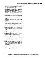
ENGINE/GENERATOR CONTROL PANEL
5.
AC Ammeter — Indicates the amount of current the
load is drawing from the generator per leg selected by
the ammeter phase-selector switch.
6.
AC Voltmeter — Indicates the output voltage present
at the
U,V, and W Output Terminal Lugs.
7.
Fuel Leak Detected Alarm Lamp — This lamp when
ON indicates that fluids in the containment area have
reach a high level.
8.
Warning Lamp — This lamp turns ON when an engine
fault/failure has occured, Reference
Troubleshooting
Diagnostic Lamp
section in this manual for fault code
details.
9.
Hour Meter — Indicates the operational hours of the
generator.
10.
Pre-Heat Lamp —
When the Auto Start/Stop Switch is
placed in the manual position, this lamp will illuminate to
indicate preheating of the engine glow plugs. When the
lamp turns off, this indicates that the preheat cycle is
complete and the engine can be started.
11.
Auto Start-Stop Switch — This switch selects either
manual or automatic operation. Center position is OFF
(reset).
12.
Engine Speed Switch — This switch controls the
speed of the engine low or high.
13.
Voltage Regulator Control — Allows ±15% manual
adjustment of the generator’s output voltage.
14.
Ammeter Change-Over Switch — This switch allows
the AC ammeter to indicate the current flowing to the load
connected to any phase of the output terminals, or to be
switched off. This switch does not effect the generator
output in any fashion, it is for current reading only.
15.
Voltmeter Change-Over Switch — This switch allows
the AC voltmeter to indicate phase to phase voltage
between any two phases of the output terminals or to
be switched off.
16.
Main Circuit Breaker — This three-pole, 60 amp main
breaker is provided to protect the
U,V, and W Output
Terminal Lugs from overload.


