PAGE 44 — DCA-70SSJU SERIES — OPERATION AND PARTS MANUAL (STD) — REV. #5 (06/03/03)
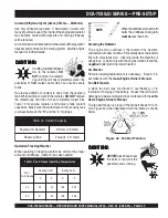
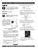
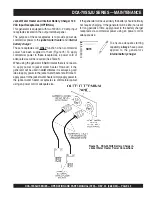
Figure 66. Auto-Off/Reset-Manual Switch
Figure 65. Engine Speed Switch (Low)
23. Set engine speed switch to “
LOW
” (Figure 65).
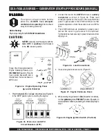
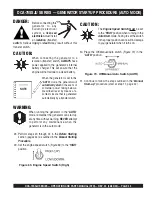
25. Once the engine is warm and the engine is running properly,
set the engine speed switch to “
HIGH
” (Figure 67).
24. Place the Auto-Off/Reset-Manual switch in the
“
MANUAL
”
position to start the engine (Figure 66). Once
the engine starts, let the engine run for 1-2 minutes.
Listen for any abnormal noises.
Figure 67. Engine Speed Switch (High)
WARNING:
WARNING:
WARNING:
WARNING:
WARNING:
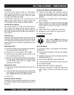
The engine's exhaust contains harmful
emissions.
ALWAYS have adequate
ventilation when operating
. Direct exhaust
away from nearby personnel.
DCA-70SSJU SERIES — GENERATOR START-UP PROCEDURE (MANUAL)
NEVER!
manually start the engine with the
main
,
GFCI
or
auailliary
circuit breakers in
the
ON
(closed) position.
CAUTION:
Before Starting
Engine Operating Panel
S/N 73002141
~
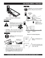
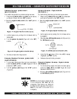
Steps 20 thru 31 are referenced
for Engine Operating Panel
S/N
73002141
~ (Figure 63). This unit
does
not
have a key ignition
switch or a throttle lever. It does
have an “
engine speed switch
”
that is used in conjunction with
the MPEC unit.
Figure 63. Engine Operating Panel
S/N 73002141~
20. Perform steps 1 through 4 in the
Before Starting
section
(page 41-42) as outlined in the
Manual Generator
Start-up
Procedure
(Engine Operating Panel up to
S/N 73002140).
21. In cold weather conditions, perform step 6 in the
Before
Starting
section (page 42) as outlined in the
Manual
Generator Start-up
Procedure
(Engine Operating Panel
up to S/N 73002140). Otherwise skip to step 22.
26.
Verify that the "
Engine Running
" status LED on the MPEC
unit (Figure 68) is "
ON
" (lit) after the engine has been started.
Figure 68. Engine Running LED (ON)
27. Continue operating the generator as outlined in steps 11
thru 19 (pages 42-43).
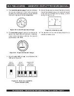
Figure 64. Voltage Selector
Switch
22. Place the voltage selector switch
in the desired voltage position
(Figure 64).


