background image

DCA45SSIU4F 60 HZ GENERATOR• OPERATION MANUAL — REV. #5 (02/28/20) — PAGE 3

TABLE OF CONTENTS

DCA45SSIU4F  

60 Hz Generator

Proposition 65 Warning ........................................... 2

Table of Contents ..................................................... 3

Safety Information ............................................... 4–9

Specifications ........................................................ 10

Dimensions ............................................................ 11

Installation ....................................................... 12–13

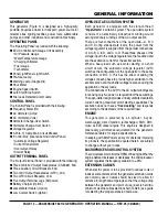
General Information ............................................... 14

Major Components ................................................ 15

Engine/Generator Control Panel...................... 16–17

Output Terminal Panel Familiarization ............. 18–20

Load Application .................................................... 21

Generator Outputs ................................................. 22

Generator Outputs/Gauge Reading ....................... 23

Output Terminal Panel Connections ................ 24–25

Inspection/Setup .............................................. 26–30

Generator Start-Up Procedure (Manual) ......... 31–32

Generator Start-Up Procedure (Auto Mode) .......... 33

Generator Shutdown Procedure ............................ 34

Maintenance .................................................... 35–44

Troubleshooting (Diagnostics) ............................... 45

Troubleshooting (Generator) .................................. 46

Troubleshooting (Engine) ................................. 47–48

Generator Wiring Diagram ..................................... 49

Engine Wiring Diagram S/N 7251795 And Below .. 50

Engine Wiring Diagram S/N 7251796 And Above . 51

Controller Wiring Diagram ..................................... 52

Battery Charger Wiring Diagram ........................... 54

Jacket Water Heater Wiring Diagram ..................... 55

Summary of Contents for WHISPERWATT DCA45SSIU4F

Page 1: ...lication or associated parts manual visit our website at www mqpower com THIS MANUAL MUST ACCOMPANY THE EQUIPMENT AT ALL TIMES WHISPERWATT SERIES MODEL DCA45SSIU4F 60Hz GENERATOR ISUZU 4LE2X DIESEL ENGINE Revision 5 02 28 20 OPERATION MANUAL ...

Page 2: ...PAGE 2 DCA45SSIU4F 60 HZ GENERATOR OPERATION MANUAL REV 5 02 28 20 PROPOSITION 65 WARNING ...

Page 3: ...ion 21 Generator Outputs 22 Generator Outputs Gauge Reading 23 Output Terminal Panel Connections 24 25 Inspection Setup 26 30 Generator Start Up Procedure Manual 31 32 Generator Start Up Procedure Auto Mode 33 Generator Shutdown Procedure 34 Maintenance 35 44 Troubleshooting Diagnostics 45 Troubleshooting Generator 46 Troubleshooting Engine 47 48 Generator Wiring Diagram 49 Engine Wiring Diagram S...

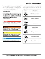
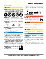
Page 4: ...ety messages specifically address the level of exposure to the operator and are preceded by one of four words DANGER WARNING CAUTION or NOTICE SAFETY SYMBOLS DANGER Indicates a hazardous situation which if not avoided WILL result in DEATH or SERIOUS INJURY WARNING Indicates a hazardous situation which if not avoided COULD result in DEATH or SERIOUS INJURY CAUTION Indicates a hazardous situation wh...

Page 5: ...d by MQ Power for this generator Damage to the generator and or injury to the user may result ALWAYS know the location of the nearest fire extinguisher ALWAYS know the location of the nearest first aid kit ALWAYS know the location of the nearest phone or keep a phone on the job site Also know the phone numbers of the nearest ambulance doctor and fire department This information will be invaluable ...

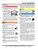
Page 6: ...ks that can start fires around dry vegetation A spark arrestor may be required The operator should contact local fire agencies for laws or regulations relating to fire prevention requirements CAUTION NEVER touch the hot exhaust manifold muffler or cylinder Allow these parts to cool before servicing the generator NOTICE NEVER run the engine without an air filter or with a dirty air filter Severe en...

Page 7: ...eting Department of Transportation DOT SafetyTowing Regulations before towing your generator Refer to the MQ Power trailer manual for additional safety information In order to reduce the possibility of an accident while transporting the generator on public roads ALWAYS make sure that the trailer that supports the generator and the towing vehicle are both mechanically sound and in good operating co...

Page 8: ...ing serious injury or even death Power Cord Cable Safety DANGER NEVER let power cords or cables lay in water NEVER stand in water while AC power from the generator is being transferred to a load NEVER use damaged or worn cables or cords when connecting equipment to the generator Inspect the insulation for cuts NEVER grab or touch a live power cord or cable with wet hands The possibility exists of ...

Page 9: ...disposal of any electrical components waste or oil associated with this equipment When the life cycle of this equipment is over remove the battery and bring it to an appropriate facility for lead reclamation Use safety precautions when handling batteries that contain sulfuric acid When the life cycle of this equipment is over it is recommended that the frame and all other metal parts be sent to a ...

Page 10: ...erload Protection OCR main circuit breaker Aux Voltage Output 120V 4 8 kW 2 4 kW 2 Dry Weight 2 337 lb 1 060 kg Wet Weight 2 976 lb 1 350 kg Table 2 Engine Specifications Model Isuzu 4LE2X Emission Regulation EPA Tier 4 Final Type 4 Cycle Water cooled direct injection turbo charged air cooled EGR No of Cylinders 4 Bore Stroke 3 35 in 3 78 in 85 mm 96 mm Displacement 133 cu in 2 17 liters Rated Out...

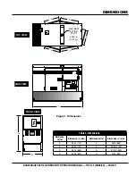
Page 11: ...VIEW H SIDE VIEW G B C D E A 45 45 MAXIMUM LIFTING POINT 6 960 lb 3 157 kg TOP VIEW Table 3 Dimensions Reference Letter Dimension in mm Reference Letter Dimension in mm A 28 34 720 E 26 18 665 B 28 34 720 F 83 86 2 130 C 26 18 665 G 61 02 1 550 D 32 28 820 H 37 40 950 Figure 1 Dimensions ...

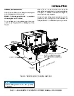
Page 12: ...f use EXAMPLEofhowtogroundtheunitifthecondition of use requires such a device The ground terminal on the generator should always be used to connect the generator to a suitable ground when required Either copper or aluminum wire can be used as the ground cable Cable size is determined by the maximum amperage of the generator Reference Conductor Grounding Table Article 250 of the NEC handbook Connec...

Page 13: ...or They are to resist damage to the bottom of the generator and to maintain alignment CAUTION Pay close attention to ventilation when operating the generator inside tunnels and caves The engine exhaust contains noxious elements Engine exhaust must be routed to a ventilated area GENERATOR GROUNDING If applicable to guard against electrical shock and possible damage to the equipment it is important ...

Page 14: ... from the parallel connections of A to B A to D and C to D These three phases of the voltage input to the voltage regulator are then rectified and are the excitation current for the exciter section When a heavy load such as a motor starting or a short circuit occurs the automatic voltage regulator AVR switches the configuration of the open delta to the series connection of B to C This has the effe...

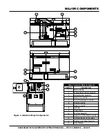
Page 15: ...re 3 Generator Major Components Table 4 Generator Major Components ITEM NO DESCRIPTION 1 DOC Assembly 2 Voltage Selector Switch Assembly 3 Output Terminal Assembly 4 Generator Assembly 5 Output Receptacles Assembly 6 Engine Assembly 7 Battery Assembly 8 Oil Drain 9 Coolant Drain 10 Fuel Tank Assembly 11 Generator Control Panel Assembly 12 Controller Gauge Unit Assembly 13 Engine Control Panel Asse...

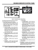
Page 16: ...r Speed Engine Started Low Fuel ECU Integrated Gauge Control R n min D D n min A B C PSI OIL PRESS 0 25 50 75 100 D E F 2 3 4 5 6 9 7 8 10 11 12 16 15 14 13 Low Oil Pressure High Temp Over Crank Over Speed Engine Started Low Fuel ECU Integrated Gauge Control R n min D D n min 1 F Warning LEDs LowOilPressureLED This LED will light when the engine oil pressure drops to 14 2 psi This condition will c...

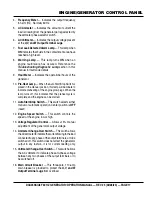
Page 17: ...tion this lamp will illuminate to indicate preheating of the engine glow plugs When the lamp turns off this indicates that the preheat cycle is complete and the engine can be started 11 Auto Start Stop Switch This switch selects either manual or automatic operation Center position is OFF reset 12 Engine Speed Switch This switch controls the speed of the engine low or high 13 Voltage Regulator Cont...

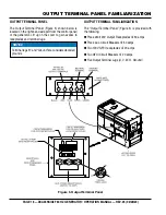
Page 18: ...or Lift up on the cover to gain access to receptacles and terminal lugs NOTICE Terminal legs O and Ground are considered bonded grounds OUTPUTTERMINAL FAMILIARIZATION The Output Terminal Panel Figure 5 is provided with the following Three 240 120V Output Receptacles 50 amps Three Aux Circuit Breakers 50 amps Two 120V GFCI receptacles 20 amps Two GFCI Circuit Breakers 20 amps Five Output Terminal L...

Page 19: ...ock Auxiliary Receptacles NOTICE It is recommended that the GFCI receptacles be tested when the generator is initially uncrated The receptacles should then be tested daily at startup SINGLE PHASE 240 120 VAC 50 AMP OUTPUT CS6369 TWIST LOCK RECEPTACLES Each auxiliary receptacle is protected by a 50 amp circuit breaker These breakers are located directly above the GFCI receptacles Remember the load ...

Page 20: ...PTACLE LOAD CS 6369 TWIST LOCK RECEPTACLES CAMLOCKS Overcurrent Relay An overcurrent relay Figure 11 is connected to the main circuit breaker In the event of an overload both the circuit breaker and the overcurrent relay may trip If the circuit breaker can not be reset the reset button on the overcurrent relay must be pressed The overcurrent relay is located inside the control box Figure 11 Overcu...

Page 21: ...00 250 ft 150 ft 100 ft 15 1 800 3 600 150 ft 100 ft 65 ft 20 2 400 4 800 125 ft 75 ft 50 ft CAUTION Equipment damage can result from low voltage NOTICE Cable selection table is a general guideline ALWAYS consult local and national electrical codes when sizing cables THREE PHASE LOAD When calculating the power requirements for 3 phase power use the following equation An inadequately sized connecti...

Page 22: ...ch Single Phase 240 120V Position 1Ø Line Neutral Line Line 120V Line Neutral N A N A 240V Line Line N A N A Maximum Amps Table 8 shows the maximum amps the generator can provide DO NOT exceed the maximum amps as listed GFCI Receptacle Load Capability The load capability of the GFCI receptacles is directly related to the voltage being supplied at either the output terminals or the three twist lock...

Page 23: ... Figure 13 Voltage Selector Switch 240 3Ø Position AC Voltmeter Gauge Reading Place the ACVoltmeter Change Over Switch Figure 14 in theW U position and observe the phase to phase voltage reading between the W and U terminals as indicated on the ACVoltmeter Gauge Figure 15 PRESS TO LOCK 3 PHASE 480 277 3 PHASE 240 139 1 PHASE 240 120 Figure 14 ACVoltmeter Change Over Switch Figure15 ACVoltmeterGaug...

Page 24: ...UVWO Terminal Lugs PRESS TO LOCK 3 PHASE 480 277 3 PHASE 240 139 1 PHASE 240 120 O U V W 240V BLACK RED BLUE 240V 240V 139V 139V WHITE GREEN GROUND CONNECTION MUST BE USED AT ALL TIMES 139V 3 Turn the voltage regulator knob Figure 20 clockwise to increase voltage output turn counterclockwise to decrease voltage output Use the voltage regulator adjustment knob whenever fine tuning of the output vol...

Page 25: ... connections to the UVWO terminals are secure and tight The possibility of arcing exists that could cause a fire 1Ø 240 120V UVWOTerminal Output Voltages 1 Place the voltage selector switch in the 1Ø 240 120 position as shown in Figure 24 Figure 24 Voltage Selector Switch 1Ø 240 120V Position 2 Connect the load wires to the UVWO terminals as shown in Figure 25 Figure 25 UVWO Terminal Lugs 1Ø 240 1...

Page 26: ...ow a safe operating condition Make sure the generator is placed on level ground Placing the generator on level ground will ensure that the low oil sensor functions properly DIPSTICK 5 If the engine oil level is low Figure 27C remove the oil filler cap Figure 28 and fill to a safe operating level max as indicated by the dipstick Figure 27A 6 Fill with recommended type oil as listed in Table 11 Maxi...

Page 27: ...ION ONLY properly trained personnel who have read and understand this section should refill the fuel tank system 45 INTERNAL FUEL TANK FUEL TANK CAP REFUELING PROCEDURE 1 LevelTanks Make sure fuel cells are level with the ground Failure to do so will cause fuel to spill from the tank before reaching full capacity Figure 30 Figure 30 Only Fill on Level Ground 2 Open cabinet doors on the right side ...

Page 28: ...oom for fuel expansion Fuel expands when heated Figure 33 Heat Source Fuel EXPANDS When Heated WARNING If adding coolant antifreeze mix to the radiator DO NOT remove the radiator cap until the unit has completely cooled The possibility of hot coolant exists which can cause severe burns 1 Verify that the coolant level in the coolant recovery tank is between the FULL and LOW markings as shown in Fig...

Page 29: ...he air cleaner Figure 36 in accordance with the maintenance section of this manual or the Isuzu Engine Owner s Manual Figure 36 Air Cleaner COOLING FINS INSPECTION SETUP FAN BELTTENSION A slack fan belt may contribute to overheating or to insufficient charging of the battery Inspect the fan belt for damage and wear and adjust it in accordance with the maintenance section of this manual or the Isuz...

Page 30: ...erminal FIRST and reconnect the negative terminal LAST POSITIVE NEGATIVE When connecting the battery do the following 1 NEVER connect the battery cables to the battery terminals when the Auto Off Reset Manual Switch is in either the AUTO or MANUAL position ALWAYS make sure that this switch is in the OFF RESET position when connecting the battery 2 Place a small amount of battery terminal treatment...

Page 31: ...art the engine with the main GFCI or auxiliary circuit breakers in the ON closed position MAIN CIRCUIT BREAKER GFCI CIRCUIT BREAKER AUXILIARY CIRCUIT BREAKER INCORRECT CORRECT STARTING MANUAL 1 Place the Auto Off Reset Manual Switch in the MANUAL position to start the engine Figure 41 Figure 41 Auto Off Reset Manual Switch Manual Position 2 Once the engine starts let the engine run for 1 2 minutes...

Page 32: ...will indicate the coolant temperature Under normal operating conditions the coolant temperature should be between 180 225 F 75 95 C Green Zone INCREASE DECREASE PSI OIL PRESS 0 25 50 75 100 Figure 47 Coolant Temperature Gauge 9 The tachometer gauge Figure 48 will indicate the speed of the engine when the generator is operating Under normal operating conditions this speed is approximately 1 800 rpm...

Page 33: ...t to the High position when running in the auto start mode Failing to set the switch in the proper position can result in damage to your generator when it turns on NOTICE When the generator is set in the AUTO mode the generator will automatically start in the event of commercial power falling below a prescribed level by means of a contact closure that is generated automatically by a transfer switc...

Page 34: ...ergency WARNING NEVER stop the engine suddenly except in an emergency MAIN CIRCUIT BREAKER GFCI CIRCUIT BREAKER AUXILIARY CIRCUIT BREAKER AUTO MANUAL OFF RESET EMERGENCY SHUTDOWN PROCEDURE Place theMAIN GFCI and LOAD circuit breakers as shown in Figure 52 to the OFF position Emergency Stop Switch Option Ifequipped option pushtheEmergencyStopPushbutton Switch Figure 54 Figure 54 Emergency Stop Butt...

Page 35: ...ter between a minimum of 100 hours and a maximum of 250 hours Service interval depends on type of oil 2 Add Supplemental Coolant Additives SCAs to recharge the engine coolant 3 Replace the primary air filter element when the restriction indicator shows a vacuum of 625 mm 25 in H2 0 4 If the blowby hose needs to be replaced ensure that the slope of the blowby hose is at least 1 2 inch per foot with...

Page 36: ... dirt and debris along with loose or damaged components NOTICE If the engine is operating in very dusty or dry grass conditions a clogged air cleaner will result This can lead to a loss of power excessive carbon buildup in the combustion chamber and high fuel consumption Change air cleaner more frequently if these conditions exist CAUTION Wear protective equipment such as approved safety glasses o...

Page 37: ...er and sediment at the bottom of the cup it should be drained off immediately FUEL FILTER ELEMENT REPLACEMENT 1 Use a filter wrench to remove the element case Figure 57 from the fuel filter body Figure 57 Fuel Filter Replacement 2 Wipe the inside of the filter body with a clean cloth to remove any foreign matter or debris that may have accumulated 3 Insert the new fuel filter element into the elem...

Page 38: ...ump housing Figure 58 Electromagnetic Fuel Pump 5 Clean or replace the fuel pump filter Replace both gaskets 6 Reassemble the fuel pump and mount it back onto the generator enclosure 7 Reconnect all fuel lines and electrical components 8 Check for fuel leaks GASKET GASKET COVER FILTER ELECTRO MAGNETIC FUEL PUMP NOTICE When the fuel pump filter is removed always make sure to replace both gaskets an...

Page 39: ...he battery Adjust the drive belt in accordance with the Isuzu Operator s manual Drive Belt Inspection Inspect the drive belt for damage and wear Horizontal cracks across the belt are acceptable Vertical direction of belt ribs cracks that intersect with horizontal cracks are not acceptable FUEL TANK Also examine the belt and determine if it is oil soaked or glazed a hard shiny appearance on the sid...

Page 40: ...nce Table 2 for engine crankcase oil capacity 6 Run the engine for several minutes Watch for oil leakage Shut the engine down and allow it to sit for several minutes Top off the oil to the upper limit on the dipstick ENGINE OIL FILTER CARTRIDGE RUBBER SEAL COAT SEAL WITH THIN LAYER OF OIL OIL FILTER WRENCH OIL 45 DRAINING ENGINE COOLANT 1 Remove the radiator pressure cap Figure 64 only if the cool...

Page 41: ...ng fins or tube When using a high pressure washer stand at least 5 feet 1 5 meters away from the radiator to prevent damage to the fins and tube Figure 66 Radiator Cleaning WARNING Allow the engine to cool when flushing out the radiator Flushing the radiator while hot could cause serious burns from water or steam TESTINGTHE GFCI RECEPTACLE If tripping of the GFCI receptacle persists after a load i...

Page 42: ...ED status LED Figure 70 is flashing do not use the GFCI receptacle and replace it immediately Figure 70 GFCI Receptacle RED Flashing LED 10 Repeat the above procedure for the other GFCI receptacle right most substituting CB5 circuit breaker GREEN LED ON GFCI RECEPTACLE ELECTRIC DRILL ON OFF SWITCH TEST BUTTON RESET BUTTON GENERATOR STORAGE For long term storage of the generator the following is re...

Page 43: ...be required See Table 6 When using the generator in hot climates there is no reason to apply power to the jacket water heater However if the generator will be used in cold climates it is always a good idea to apply power to the jacket water heater at all times If the generator will be used daily the battery should normally not require charging If the generator will be idle not used for long period...

Page 44: ...nents In general this catalyst collects burns accumulated particulates The DOC contains palladium and platinum which serve as catalysts to oxidize hydrocarbons and carbon monoxide EMISSION CARBON CHECK Deposition of carbon soot unburned fuel in the exhaust pipe line and muffler could cause not only system derates but also could lead to fires To reduce soot and unburned fuel run the unit at rated p...

Page 45: ...c procedures 6 Verify that the diagnostic lamp is ON This indicates that there is a fault error in the engine or the engine control system 7 Push and hold the diagnostic button to identify the fault and verify the following The diagnostic lamp will start blinking with a pattern according to the detected fault code 3 times at an interval rate of 2 4 seconds If two or more fault codes are detected t...

Page 46: ... position Is wiring connection loose Check wiring and repair Defective AVR Replace if necessary High Voltage Output Is wiring connection loose Check wiring and repair Defective AVR Replace if necessary Circuit Breaker Tripped Short Circuit in load Check load and repair Over current Confirm load requirement and reduce Defective circuit breaker Check and replace Overcurrent Relay actuated Confirm lo...

Page 47: ...gine oil too thick Refill engine crankcase with correct type of oil for winter environment Defective battery Replace battery Engine fires but stops soon as starter is switched off Fuel filter blocked Replace fuel filter Fuel supply blocked Check the entire fuel system Defective fuel pump Replace fuel pump Engine stops by itself during normal operation Fuel tank empty Add fuel Fuel filter blocked R...

Page 48: ...heats Too much oil in engine crankcase Drain off engine oil down to uppermark on dipstick Entire cooling air system contaminated blocked Clean cooling air system and cooling fin areas Fan belt broken or elongated Change belt or adjust belt tension Coolant insufficient Replenish coolant Radiator net or radiator fin clogged with dust Clean net or fin carefully Fan radiator or radiator cap defective ...

Page 49: ...IELD WINDING RECTIFIER AUTOMATIC VOLTAGE REGULATOR VOLTAGE REGULATOR RHEOSTAT CURRENT TRANSFORMER CHANGE OVER SWITCH AMMETER AC AMMETER CHANGE OVER SWITCH VOLTMETER AC VOLTMETER FREQUENCY METER CIRCUIT BREAKER 3P 110A CIRCUIT BREAKER 2P 50A CIRCUIT BREAKER 1P 20A RECEPTACLE 250V 50A RECEPTACLE 125V 20A X 2 GFCI OVER CURRENT RELAY SELECTOR SWITCH RELAY UNIT CB2 3 4 CB5 6 CON1 2 3 CON4 5 CN1 CN3 CN4...

Page 50: ...NG VIEW B V24 C L V11 V51 V10 BAT MAIN CN2 B L G V P R W Y O BR GR LB LG WIRE COLOR BLACK BLUE BROWN GREEN GRAY VIOLET PINK ORANGE LIGHT GREEN LIGHT BLUE YELLOW WHITE RED SYM SYM WIRE COLOR COLOR CODE V14 V46 C H 1 2 3 4 CN1 GND 1 2 3 B AC AC2 C TB2 TERMINAL BOARD 1 2 5 6 3 RELAY INNER CIRCUIT STARTER CUT RELAY MAIN RELAY FUEL PUMP RELAY ...

Page 51: ... VIEW B V24 C L V11 V51 V10 BAT MAIN CN2 B L G V P R W Y O BR GR LB LG WIRE COLOR BLACK BLUE BROWN GREEN GRAY VIOLET PINK ORANGE LIGHT GREEN LIGHT BLUE YELLOW WHITE RED SYM SYM WIRE COLOR COLOR CODE V14 V46 C H 1 2 3 4 CN1 GND 1 2 3 B AC AC2 C TB2 TERMINAL BOARD 1 2 5 6 3 RELAY INNER CIRCUIT STARTER CUT RELAY MAIN RELAY FUEL PUMP RELAY V25 ...

Page 52: ...PAGE 52 DCA45SSIU4F 60 HZ GENERATOR OPERATION MANUAL REV 5 02 28 20 CONTROLLER WIRING DIAGRAM ...

Page 53: ...DCA45SSIU4F 60 HZ GENERATOR OPERATION MANUAL REV 5 02 28 20 PAGE 53 NOTES ...

Page 54: ...MA 5 15 15A 120 VAC P N EE6176 HBL5278C HUBBLE RECEPTACLE NOTES 1 2 RECEPTACLE IS MOUNTED ON OUTPUT TERMINAL PANEL ASSY 20 AMP 5 20R RECEPTACLE P N EE6131 HBL5369C HUBBLE RECEPTACLE 3 4 CORD CAROL 3 C 14 AWG P N EE56557 120 VAC INPUT INSERT EXTERNAL POWER CORD HERE 3 1 2 4 BLACK 14 AWG LINE L 120VAC INPUT WHITE 14 AWG NEUTRAL N GREEN 14 AWG GROUND G 1 2 3 4 A B A B ...

Page 55: ...G NEUTRAL N GREEN 14 AWG GROUND G NOTES 1 2 RECEPTACLE IS MOUNTED ON OUTPUT TERMINAL PANEL ASSY 20 AMP 5 20R RECEPTACLE P N EE6131 HBL5369C HUBBLE RECEPTACLE 3 GROUND 120 VAC 4 CORD CAROL 3 C 14 AWG P N EE56557 BLOCK HEATER P N 44558 120 VAC INPUT INSERT EXTERNAL POWER CORD HERE 3 1 2 4 HEATING ELEMENT TEMP SWITCH BLACK 14 AWG LINE L 120VAC INPUT WHITE 14 AWG NEUTRAL N GREEN 14 AWG GROUND G 1 2 3 ...

Page 56: ...ined in this manual are for guidance only and may not be considered as binding Multiquip Inc reserves the right to discontinue or change specifications design or the information published in this publication at any time without notice and without incurring any obligations Manufactured for Multiquip Inc by DENYO MANUFACTURING CORP HERE S HOW TO GET HELP PLEASE HAVE THE MODEL AND SERIAL NUMBER ON HA...

Reviews: