background image

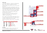
#03 axes & motors

Y-Axis

X-Axis

Z-Axis

Endstops

2x Motor

Micro stepping

Enable pin

Driver socket

Z1

Y1
X1

Z2

Y2

X2

Motor axes: 

The Mr Beam Shield can control up to 3 independent 
axes. It has 3 sockets compatible with Pololu/
Stepstick stepper drivers like the ones used on many 
3D-printers.
While the Z axis has only a single stepper motor, the 
other axes have double motor connectors. This allows 
to drive two steppers with a single driver and is useful 
for a double motor axis like the Y-axis on a Mr Beam 
Senior. The connectors are using the reprap-style pin 
order (1b, 1a, 2a, 2b). Turning the connector 180° 
inverts the motor direction.  
Check the orientation of a stepper driver before 
plugging it in. The "enable" pin of the driver is 
marked on the shield as well. 

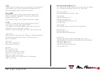
The 3 jumpers marked with MS1, MS2, MS3 configure 
the micro stepping mode of the driver. Depending on 
the driver's chipset the modes may differ.
This table shows the settings for the common A4988 
chip: 

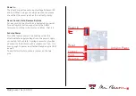
Endstops:

The shield provides 2 endstop connectors for each 
axis. Micro switches can be attached directly, 

MS1

MS2

MS3

Microstep Resolution
Full step
Half step
Quarter step
Eighth step
Sixteenth step

1b

1a

2a

2b

Summary of Contents for Shield

Page 1: ...back front Mr Beam Shield Instructions 01 laser driver 02 power source 03 axes motors 04 miscellaneous 05 safety 06 usage appendix ...

Page 2: ...inally the shield was designed for the Mr Beam laser cutter kit but it can be used for every laser device which uses stepper motors in the mechanics Besides laser cutters this can be laser sintering 3D printers 3D scanners laser projectors or other robots Thank you Have fun By purchasing this shield you have supported a piece of open hardware thank you We enjoyed the development of it and will con...

Page 3: ...your laser diode Before connecting the laser diode check twice the polarity of your diode the cable and the connectors in between A false polarity will destroy your diode Interlock connectors The shield provides 2 connectors for interlock switches or sensors Both have to be closed for operating the laser Cooling Fan Connect a cooling fan at this two pins The voltage supplied at the pin equals the ...

Page 4: ...r for each control button supported by the GRBL firmware Just plug in the button s cables that s it Arduino Power This little feature powers the Arduino under the shield with the supply voltage from the power supply connected to the shield A voltage converter provides 5V output to the Arduino with a maximum of 1 5A It is even enough to power an attached Raspberry via USB as well To enable this fea...

Page 5: ...he Y axis on a Mr Beam Senior The connectors are using the reprap style pin order 1b 1a 2a 2b Turning the connector 180 inverts the motor direction Check the orientation of a stepper driver before plugging it in The enable pin of the driver is marked on the shield as well The 3 jumpers marked with MS1 MS2 MS3 configure the micro stepping mode of the driver Depending on the driver s chipset the mod...

Page 6: ...The RX TX pins have 3 3v logic levels but it is no problem to use them with 5v as well if the counterpart is flexible as well Additionally there are both voltage levels and ground available as well Sensor Input Though the analog Arduino pins A4 and A5 are not used in standard GRBL firmware the shield is ready for future developments and provides own connectors for them In combination with a 5v and...

Page 7: ...ls on it according to your local regulations Some examples of such labels are shown on the right Check your local regulations for chosing the right ones LASER RADIATION LASER RADIATION AVOID EYE OR SKIN EXPOSURE TO DIRECT OR SCATTERED RADIATION CLASS 4 LASER PRODUCT Max Power 1000mW Wavelength 400 695nm Classified according IEC 60825 1 2007 LASER APERTURE Safety Glasses Laser light is very intense...

Page 8: ...re it will be switched on M05 switch laser off Fan Control M08 switch cooling fan on M09 switch cooling fan off Movement H do a homing cycle G21 switch to mm units G90 switch to absolute coordinates G92 X0 Y0 Z0 set coordinate origin G0 X Y rapid positioning move G1 X Y move to given position with the current feedrate F set feedrate Additional Information Resources The internet is full of informat...

Reviews: