Connecting the FM Antenna
and Auxiliary Cord
1.
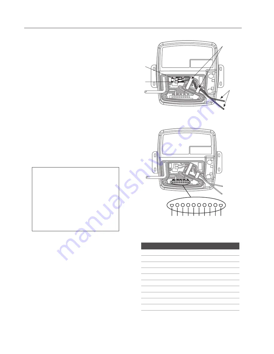
Plug the included FM antenna into the antenna
output and route the wire through the strain relief
channel as illustrated (
Figure 9)
. For best recep-
tion, fully deploy the antenna in a vertical orienta-
tion outside of the AudioSteam housing.
2.
Connect a 1/8” (3.5 mm) stereo audio cord (not
included) to the auxiliary output, and route the
cable through the strain relief channel as illus-
trated (
Figure 9
). Connect the free end of the
audio cord to a mobile device or digital music
player.
Connecting Speakers
and Subwoofer
1.
Connect individual speaker wires — or a 10-pin
MATE-N-LOK adapter with attached wires — to
the speaker outputs. Refer to
Figure 10
and
Figure 11
for connector identification.
2.
Route the wires through the molded relief chan-
nel. Connect the speaker wires to suitable speak-
ers and subwoofer.
3.
Replace the foam block inserts (
Figure 9
).
4.
Secure the cover using the two cover screws.
9
10 9 8 7 6 5 4 3 2 1
Figure 10
Figure 11
Figure 9
Auxiliary
Cord
FM
Antenna
Route
Wires
Replace
Foam
Blocks
CONNECTION
IDENTIFICATION
COlOR
1
Front Left speaker (+)
White
2
Front Left speaker (-)
White/Black
3
Front Right speaker (-)
Grey/Black
4
Front Right speaker (+)
Grey
5
Rear Left speaker (+)
Green
6
Rear Left speaker (-)
Green/Black
7
Rear Right speaker (-)
Purple/Black
8
Rear Right speaker (+)
Purple
9
Subwoofer (+)
Blue
10
Subwoofer (-)
Blue/Black
IMPORTANT NOTES
• If you use individual speaker wires, the rec-
ommended socket crimping contact is an
AWG 14-20 (TE Connectivity part number
350550-3).
• If you use a 10-pin MATE-N-LOK adapter
with attached wires, the required hous-
ing connector is a 10-position Universal
MATE-N-LOK (TE Connectivity part number
926302-3).
mr
.
steam
®
INSTALLATION, OPERATION, AND MAINTENANCE
AudioSteam
®
All drawings are for illustrative purposes only.
AudioHome only uses positions 1, 2, 3 & 4
INST
ALLER
Summary of Contents for AudioSteam
Page 17: ......


