mr
.
steam
®
Electric Towel Warmers
Installation and Operating Instructions
________________________________________________________________
8
TO PREVENT SHOCK HAZARD, TURN OFF ELECTRICITY AT THE MAIN PANEL
BEFORE WIRING. VERIFY WITH MULTIMETER.
The Towel Warmer is an electronically operated device. It must be installed by a
licensed electrician in accordance with local code and the National Electric Code (NEC). The Towel
Warmer must be located in accordance with any prevailing codes and relevant electrical wiring rules
and regulations, in particular regulations that cover the use of products and accessories in damp
situations such as bathrooms, showers, laundries and other areas with fixed water containers.
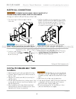
Install a wall switch or timer to turn the Towel Warmer on and off.
NOTE:
When the Towel Warmer is energized, the indicator light on the Towel Warmer will illumi-
nate. DO NOT alter or modify any MrSteam products. Doing so may result in an inoperable or haz-
ardous installation and will void the warranty.
NOTE:
The Towel Warmer wires are color coded: BLACK for LINE, WHITE for NEUTRAL, GREEN/
YELLOW for EQUIPMENT GROUND.
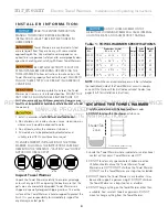
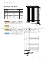
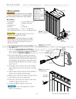
A single gang electric box must be roughed-in, see page 4 for location.
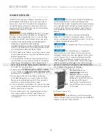
Install Towel Warmers in upright position only. Locate with pilot light on bottom as shown.
Failure to install properly may result in over-heating and a hazardous condition.
ELECTRICAL CONNECTIONS
General
The Towel Warmer requires 120VAC, 60 Hz power supply and must be GFCI protected.
Specific amperage needed is listed in the Towel Warmer Specifications Chart on page 4.
A. Electrical connections should be made as prescribed by the National Electric and Local Codes. The unit
should be field wired using 14 AWG min 90°C-rated copper wire. All models are to be protected by a
separate 15 amp circuit breaker or equal.
B. Make connections between Towel Warmer and house wiring using approved connections to comply with
National Electrical Local Codes. LINE (black), NEUTRAL (white), and GROUND.
C. Install the Towel Warmer according to the specific instructions for each model.
D. A dedicated circuit is required.
TO PREVENT SHOCK HAZARD, NO BARE WIRE OR
WIRE STRANDS SHOULD BE VISIBLE AFTER MAKING CONNECTIONS.
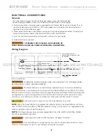
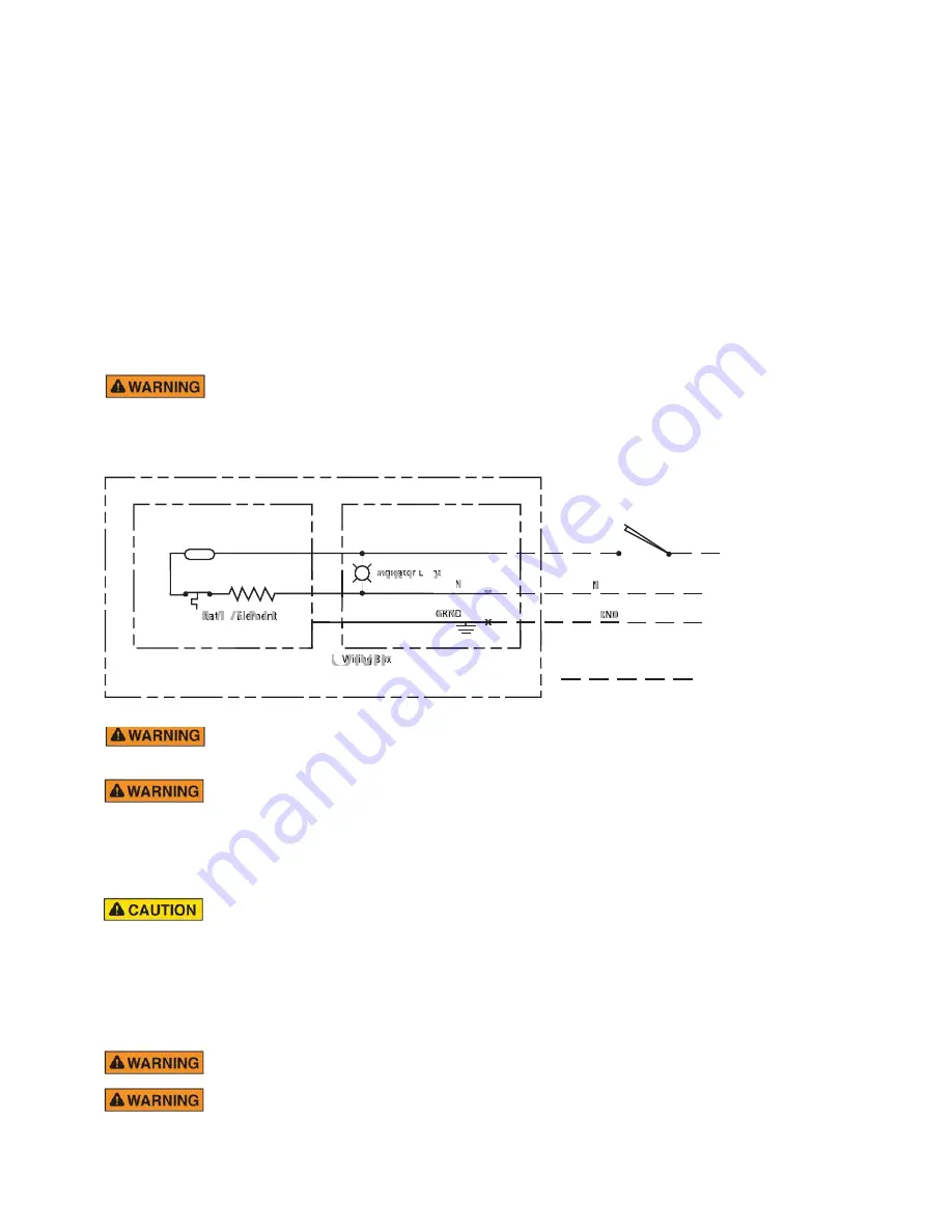
Wiring Diagram
Electric Towel Warmer
Thermal Fuse
Thermostat Element
Heating Element
Wiring Box
Field Wiring
L
N
GRND
L
N
GRND
Field Installed Wall Switch or
Mr. Steam Digital Programmable Timer
PN: 103588DIG
Indicator Light
X
X
X
REF
FER
E
TO
O
O
,
INSTALLAT
L T
INSTALLATION,
INSTALLATION,
O
TI
N
TI
TIO
I
Indicato
OPERATION
AT
A
OPE
O
N
N
ht
X
X
X
AND
AINTENANCE
MA
MANUAL
A
AL
stat Element
PROVIDED
P
PROVIDED
P
PROVIDE
ED
GRND
E
E
WITH
W
WITH
T
PRODUCT
RO
OD
DU
P
RND
FOR
FOR
COMPLETE
COMPLETE
Wiring Box
INSTRUCTIONS
T
INS


