background image

Table of contents

Maschinenfabrik Reinhausen GmbH 2016

3

5163667/00 EN

TRAFOGUARD® ISM®

Table of contents

1

Introduction.........................................................................................................................  9

1.1

Manufacturer.......................................................................................................................................  9

1.2

Completeness...................................................................................................................................... 9

1.3

Safekeeping......................................................................................................................................... 9

1.4

Notation conventions...........................................................................................................................  9

1.4.1

Hazard communication system.............................................................................................................................  9

1.4.2

Information system..............................................................................................................................................  11

1.4.3

Instruction system...............................................................................................................................................  11

1.4.4

Typographic conventions....................................................................................................................................  12

2

Safety.................................................................................................................................  13

2.1

Appropriate use.................................................................................................................................  13

2.2

Fundamental Safety Instructions.......................................................................................................  13

2.3

Personnel qualification......................................................................................................................  15

2.4

Personal protective equipment..........................................................................................................  16

3

Product description..........................................................................................................  18

3.1

Scope of delivery...............................................................................................................................  18

3.2

Function description..........................................................................................................................  18

3.3

Performance features........................................................................................................................  19

3.4

Design...............................................................................................................................................  20

3.4.1

Power supply....................................................................................................................................................... 21

3.4.2

Power supply....................................................................................................................................................... 22

3.4.3

Central processing unit........................................................................................................................................ 22

3.4.4

Voltage measurement and current measurement...............................................................................................  23

3.4.5

Digital inputs and outputs....................................................................................................................................  23

3.4.6

Analog inputs and outputs................................................................................................................................... 24

3.4.7

Media converter................................................................................................................................................... 25

3.4.8

Media converter with managed switch................................................................................................................  26

3.5

Operating concept.............................................................................................................................  26

4

Mounting............................................................................................................................  30

4.1

Preparation........................................................................................................................................  30

4.2

Electromagnetic compatibility............................................................................................................  30

4.2.1

Wiring requirement of installation site ................................................................................................................  31

Summary of Contents for TRAFOGUARD ISM

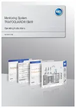
Page 1: ...Monitoring System TRAFOGUARD ISM Operating Instructions 5163667 00 EN ...

Page 2: ... for compensation All rights reserved in the event of the granting of patents utility models or designs The product may have been altered since this document was published We reserve the right to change the technical data design and scope of supply Generally the information provided and agreements made when processing the individual quotations and orders are binding The original operating instruct...

Page 3: ... 2 3 Personnel qualification 15 2 4 Personal protective equipment 16 3 Product description 18 3 1 Scope of delivery 18 3 2 Function description 18 3 3 Performance features 19 3 4 Design 20 3 4 1 Power supply 21 3 4 2 Power supply 22 3 4 3 Central processing unit 22 3 4 4 Voltage measurement and current measurement 23 3 4 5 Digital inputs and outputs 23 3 4 6 Analog inputs and outputs 24 3 4 7 Medi...

Page 4: ...rmation about laying fiber optic cable 45 4 6 4 Mounting terminating resistor of CAN bus 45 4 6 5 Connecting cables to the system periphery 45 4 6 6 Wiring the CPU I assembly 46 4 6 7 Wiring the UI assembly 49 4 6 8 Wiring the AIO assembly 51 4 6 9 Wiring the DIO assembly 56 4 6 10 Wiring the MC 2 2 SW3 3 assembly 58 4 6 11 Wiring the G1 PULS assembly 60 4 6 12 Connecting the power supply 62 5 Com...

Page 5: ... variable 105 6 4 3 Regulation mode 105 6 5 Control of the motor drive unit optional 105 6 5 1 Setting the switching pulse for controlling the motor drive unit 106 6 5 2 Setting motor runtime monitoring 107 6 5 3 Setting the switching direction 107 6 6 Parallel operation optional 108 6 6 1 Activating parallel operation 109 6 6 2 Selecting parallel operation method 109 6 6 3 Assigning a CAN bus add...

Page 6: ...wear only OILTAP 139 6 17 Configuring analog inputs and outputs optional 139 6 18 Name plate optional 141 6 18 1 Enter the name plate data 142 6 18 2 Displaying the name plate 142 6 19 Maintenance optional 143 6 19 1 Setting operator interval for OLTC maintenance 144 6 19 2 Setting operator interval for transformer maintenance 145 6 19 3 Undertaking and confirming maintenance 146 6 19 4 Displaying...

Page 7: ... 25 Information about device 181 6 25 1 Hardware 181 6 25 2 Software 182 6 25 3 Parallel operation 182 6 26 Import export manager 183 6 26 1 Exporting data 183 6 26 2 Importing data 184 6 27 Linking signals and events 185 6 27 1 Linking functions 186 6 27 2 Linking digital outputs and control system messages 187 7 Fault elimination 190 7 1 General faults 190 7 2 Human machine interface 190 7 3 Oth...

Page 8: ...06 10 2 Voltage supply 206 10 3 Voltage measurement and current measurement 207 10 4 Digital inputs and outputs 208 10 5 Analog inputs and outputs 210 10 6 Central processing unit 211 10 7 System networking 213 10 8 Ambient conditions 214 10 9 Standards and directives 215 11 Appendix 217 11 1 Check list for commissioning 217 Glossary 218 List of key words 219 ...

Page 9: ...gensburg Germany Tel 49 9 41 40 90 0 Fax 49 9 41 40 90 7001 E mail sales reinhausen com Further information on the product and copies of this technical file are avail able from this address if required Completeness This technical file is incomplete without the further applicable documentation The following documents apply to this product Operating instructions Connection diagrams Safekeeping Keep ...

Page 10: ...ating to sec tions Embedded warnings use the following format DANGER Instruction for avoiding a dangerous situation Signal words and pictograms The following signal words are used Signal word Meaning DANGER Indicates a hazardous situation which if not avoided will result in death or serious injury WARNING Indicates a hazardous situation which if not avoided could result in death or serious injury ...

Page 11: ...e it is laid out as follows Important information Instruction system This technical file contains single step and multi step instructions Single step instructions Instructions which consist of only a single process step are structured as fol lows Aim of action ü Requirements optional Step 1 of 1 ð Result of step optional ð Result of action optional Multi step instructions Instructions which consis...

Page 12: ...ntions are used in this technical file Typographic convention Purpose Example UPPERCASE Operating controls switches ON OFF Brackets PC keyboard Ctrl Alt Bold Software operating controls Press Continue button Menu paths Parameter Control parameter Italics System messages error mes sages signals Function monitoring alarm trig gered Number of pages Cross reference 41 Table 3 Typographic conventions 1...

Page 13: ...liance with the requirements and conditions specified in this technical file as well as with the warnings in this technical file and attached to the product then the product does not present any danger to people property or the environment This applies throughout the product s entire life from delivery to installation and operation through to disassembly and disposal The following is considered ap...

Page 14: ...dy Make sure that the work area is well lit Observe the applicable laws for accident prevention in the relevant country Working during operation You must only operate the product when it is in a sound operational condi tion Otherwise it poses a danger to life and limb Regularly check the operational reliability of safety equipment Comply with the maintenance work and maintenance intervals descri b...

Page 15: ... nance and inspection must ensure that the personnel are sufficiently quali fied Electrically skilled person The electrically skilled person has a technical qualification and therefore has the required knowledge and experience and is also conversant with the ap plicable standards and regulations The electrically skilled person is also pro ficient in the following Can identify potential dangers ind...

Page 16: ...d authorized by Maschinenfabrik Reinhausen GmbH to carry out the work Authorized personnel Authorized personnel are trained by Maschinenfabrik Reinhausen GmbH to carry out special maintenance Personal protective equipment Personal protective equipment must be worn during work to minimize risks to health Always wear the personal protective equipment required for the job at hand Never wear damaged p...

Page 17: ...lasses To protect the eyes from flying parts and splashing liquids Visor To protect the face from flying parts and splashing liquids or other dangerous sub stances Hard hat To protect from falling and flying parts and materials Hearing protection To protect from hearing damage Protective gloves To protect from mechanical thermal and electrical hazards ...

Page 18: ...ess on the basis of the shipping docu ments Store the parts in a dry place until installation Function description The device is used to record the measured values and status data of a pow er transformer and an on load tap changer and to make them available us ing a web based visualization In addition to this the parameters can be changed via the visualization You can set the required parameters f...

Page 19: ... tap changer monitoring Contact wear calculation only for OILTAP V M R RM MS G Maintenance interval calculation Oil carbonization only for OILTAP V M R Monitoring of OLTC temperature optional Tap change statistics of on load tap changer Optional on load tap changer oil level Optional oil filter unit Status of the motor drive unit motor protective switch motor is run ning Automatic voltage regulati...

Page 20: ...ependent mode for early activation of cooling stages Periodic mode for regular activation of cooling stages Alternating mode for equal loading of similar cooling stages Cooling stage monitoring 2 4 or 6 cooling stages DGA Up to 10 gases via analog input Relative moisture in oil via analog input Design Depending on the order the device is either designed as a 19 inch plug in housing or as individua...

Page 21: ...ponents for assembly on a cap rail Power supply The OT1205 assembly contains the power supply unit for powering the de vice Depending on configuration the device is equipped with one of the fol lowing power supply unit variants Multi voltage mains unit 85 265 V AC V DC DC voltage power supply unit 20 70 V DC 3 4 1 ...

Page 22: ...r the device s power supply Figure 4 QS3 241 assembly Central processing unit The CPU I assembly is the central computing unit for the device It contains the following interfaces Internal system interface RS232 COM1 Serial interface RS232 485 COM2 3x Ethernet ETH1 ETH 2 1 ETH 2 2 USB USB 2 0 2x CAN bus CAN 1 CAN 2 Figure 5 CPU I assembly 3 4 2 3 4 3 ...

Page 23: ...6 UI 1 assembly The UI 3 assembly is used for measuring 3 phase voltage and current Figure 7 UI 3 assembly Digital inputs and outputs The DIO 28 15 and DIO 42 20 HL assemblies provide a different number of digital inputs and outputs depending on the version DIO 28 15 28 inputs 15 outputs 6 N O contacts 9 change over con tacts DIO 42 20 HL 42 inputs 20 outputs 8 N O contacts 12 change over contacts...

Page 24: ...rovide analog inputs and outputs AIO 2 2 channels AIO 4 4 channels In accordance with the device configuration the AIO assembly supports one of the following signal types Input Output Voltage Current Voltage Current 0 10 V 0 20 mA 4 20 mA 0 10 V 0 20 mA 4 20 mA Resistance measurement such as PT100 resistor contact series Table 4 Signal types supported by the AIO assembly 3 4 6 ...

Page 25: ...erter which converts 2 electrical con nections RJ45 to one fiber optic cable connection each Each is converted independently of the other The following interfaces are available 2x RJ45 ETH12 ETH22 2x Duplex LC SFP module ETH11 ETH21 The media converter is designed to be transparent for the network and does not have its own IP address Figure 10 MC 2 2 assembly 3 4 7 ...

Page 26: ...Managed switch with redundancy function PRP or RSTP 2x RJ45 ETH23 ETH24 device internal connection 2x Duplex LC SFP module ETH21 ETH22 redundancy connec tion The following redundancy functions are available to you according to your order PRP standard setting RSTP Figure 11 SW 3 3 assembly Operating concept You can operate the device using the controls on the front panel or using the web based ISM ...

Page 27: ...on at the same time you have to log in on the device and via the visualization Proceed as follows to log in as user 1 Press the LOGIN button in the status line 2 Enter your user name and password and select the Ok button ð Logged in user appears in status line Proceed as follows to log out as user Press the LOGOUT button in the status line Navigation If you are operating the device using the contr...

Page 28: ...se rotary knob to navigate to list and press the key Figure 12 Selecting entry from list 2 Use rotary knob to highlight entry from list and press the key 3 Press the Accept button to save the modified parameter To enter a value proceed as follows 1 Use rotary knob to select the field for the value and press the key ð If operating via the front panel the numerical keypad appears Figure 13 Entering ...

Page 29: ...ress the Accept button to save the modified parameter To enter text proceed as follows 1 Use rotary knob to select the text box and press the key ð If operating via the front panel the keyboard appears Figure 14 Entering text 2 Enter the text you want and confirm with 3 Press the Accept button to save the modified parameter Entering text ...

Page 30: ...ge Do not idle the current transformer short circuit the current transformer to prevent this NOTICE Electrostatic discharge Damage to the device due to electrostatic discharge Take precautionary measures to prevent the build up of electrostatic charges on work surfaces and personnel Preparation The following tools are needed for mounting Screwdriver for the fixing bolts M6 Small screwdriver for co...

Page 31: ...Do not route lines which cause interference for example power lines and lines susceptible to interference for example signal lines in the same cable duct Maintain a space of more than 100 mm between lines which cause in terference and those which are susceptible to interference Figure 15 Recommended wiring 1 Cable duct for lines causing interference 3 Cable duct for lines suscepti ble to interfere...

Page 32: ...EMC requirements Functional division of control cabinet physical separation Constant potential equalization all metal parts are joined Line routing in accordance with EMC requirements separation of lines which cause interference and those susceptible to interfer ence Optimum shielding metal housing Overvoltage protection lightning protection Collective grounding main grounding rail Cable bushings ...

Page 33: ...ntial compensation rail for potential equal ization If both devices have different potentials only connect the CAN bus ca ble s shielding to one device Variant 1 The connected devices share the same potential If the devices to be connected share the same potential proceed as follows 1 Connect all devices to a potential equalization rail to equalize the poten tial 2 Connect CAN bus cable s shieldin...

Page 34: ...nimum distances to the control cabinet and to neighboring components Minimum distance To the floor of the control cabinet 88 9 mm 3 5 in Corresponds to 2 RU To the roof of the control cabinet Between assemblies on the bus bar and assemblies on the remote cap rail Table 5 Minimum distances in the control cabinet Figure 18 Example depiction of the minimum distances in a control cabinet For other ins...

Page 35: ...ISM 2 Place device in 19 frame and screw down Figure 19 Example of device mounting in a 19 frame Mounting in a control panel with a 19 flush control panel frame To mount the device in a control panel proceed as follows ü Scope of delivery is complete Figure 20 Scope of delivery ...

Page 36: ...H 2016 36 5163667 00 EN TRAFOGUARD ISM 1 Produce cut out in control panel Figure 21 Producing cut out in control panel 2 Mounting cage nuts Figure 22 Mounting cage nuts 3 Secure frame to control panel Figure 23 Securing frame to control panel ...

Page 37: ... of flush control panel frame Figure 25 Closing cover Installing the individual components on a cap rail Fastening the cap rail The cap rail is required to install a bus bar or a device s remote assemblies in a control cabinet The following types of cap rails are to be used exclu sively in accordance with EN 60715 TH 35 7 5 TH 35 15 The cap rail must not be painted 4 5 4 5 1 ...

Page 38: ...ect the cap rail to the protective ground securely e g with a pro tective conductor line up terminal Ensure that the cap rail is connected securely to the protective ground using the ground test after installation Fasten the cap rail to the rear panel of the cabinet using screws and contact washers or lock washers The distance between the screws can be no more than 10 cm 3 94 in Figure 26 Fastenin...

Page 39: ...us rail to the cap rail WARNING Mount the bus rail to the cap rail while ensuring that the bus rail engages correctly Otherwise an electrical shock can occur as a result of a faulty connection to the protective ground Figure 27 Engaging the bus rails Installing the assembly at a distance on the cap rail As an option the device can have the following assemblies that must be mounted at a distance on...

Page 40: ...electrical connection to the device WARNING Electric shock Risk of fatal injury due to connection mistakes Ground the device with a protective conductor using the grounding screw on the housing Note the phase difference of the secondary terminals for the current transformer and voltage transformer Connect the output relays correctly to the motor drive unit Supply the voltage via separators and ens...

Page 41: ...ted with alternating current take into account the effect of the line capacitance of long control cables on the func tion of the relay contacts If you want to route Ethernet connections starting from a control cabinet or building we recommend the use of fiber optic cables in accordance with the recommendation from IEC 61850 90 4 Cable Assembly Cable type Conductor cross section Max length Power su...

Page 42: ... LC Multimode OM3 1 310 nm 2000 m Table 6 Recommendation for connection cable Observe line capacitance see note above Information about connecting serial interfaces RS232 and RS485 NOTICE Damage to the device Using the wrong data cable may damage the device Only use data cables which comply with the description below RS232 D SUB 9 pole For connecting the device via the RS232 interface COM2 use a d...

Page 43: ... Maschinenfabrik Reinhausen GmbH 2016 43 5163667 00 EN TRAFOGUARD ISM RS485 D SUB 9 pole To connect the device via the RS485 interface COM2 use a data cable with the following structure Figure 30 RS485 data cable ...

Page 44: ...ture Figure 31 Data cables for combined interface RS232 RS485 D SUB 9 pole plug connection Only use 9 pole D SUB plugs with the following characteristics Plug housing is metallic or metal plated Cable shielding is connected with the plug using one of the two following variants Shielding is screwed to the traction relief device Shielding is soldered to the plug housing Figure 32 Example of a solder...

Page 45: ... values The fiber optic cables must not be twisted Be aware of sharp edges which could damage the fiber optic cable s coating when laying or could place mechanical loading on the coating later on Provide a sufficient cable reserve near distributor cabinets for example Lay the reserve such that the fiber optic cable is neither bent nor twisted when tightened Mounting terminating resistor of CAN bus...

Page 46: ...nly the specified cables for wiring Note the cable recommenda tion Connect the lines to be wired to the device to the system periphery as shown in the connection diagrams supplied Wiring the CPU I assembly 1 Connect the ETH 2 2 interface to a PC for accessing the web based vis ualization Figure 34 Connection to a PC over an Ethernet interface 4 6 6 ...

Page 47: ...sen GmbH 2016 47 5163667 00 EN TRAFOGUARD ISM 2 Connect the ETH 1 interface to the control system SCADA in accord ance with the connection diagram Figure 35 SCADA connection Observe the information about connecting serial interfaces 42 ...

Page 48: ...to the control system SCADA in accordance with the con nection diagram Figure 36 Serial SCADA connection over the COM 2 interface Voltage supply You have to connect the CPU I component to the voltage supply of the volt age supply unit Proceed as follows 1 Guide the leads into the plug terminal and fasten them using a screw driver Figure 37 Inserting the leads ...

Page 49: ...fasten the plug into the respective 24V DC slot Figure 38 Fasten the 24V DC plug Wiring the UI assembly Proceed as follows to wire the UI assembly 1 Guide leads into corresponding connector terminals and fasten them us ing a screwdriver Figure 39 Example Connector for voltage measurement 4 6 7 ...

Page 50: ... Maschinenfabrik Reinhausen GmbH 2016 50 5163667 00 EN TRAFOGUARD ISM Figure 40 Example Connector for current measurement 2 Insert the plug into the associated slot and engage the plug Figure 41 Engaging the plug ...

Page 51: ... inputs and outputs according to the connected sen sors 139 In order to correctly record the analog signals you must place the cable shielding on the grounding bar The cable shielding should be removed as late as possible before connecting to keep the section with unshielded ca bles as short as possible The shielding must be connected with shielding clips Figure 42 Examples of supporting shielding...

Page 52: ...Figure 43 Connector assignment of AIO 2 and AIO 4 assemblies Interface Pin Description 1 6 11 16 I OUT Current output 2 7 12 17 I U IN U OUT Voltage input current input voltage output 3 8 13 18 I U IN Voltage input cur rent input 4 9 14 19 I U OUT Voltage output current output 5 10 15 20 not used Table 7 Analog inputs and outputs You can connect the following types of analog sensors 0 4 20 mA 0 10...

Page 53: ...2 3 4 5 4 20 mA signal source Figure 44 Connection example for a 4 20 mA sensor PT100 PT1000 sensor Depending on type you must connect a PT100 sensor or PT1000 sensor as follows 2 wire pin and 3 wire pin and 4 wire pin and I OUT I U IN U OUT I U IN I U OUT 1 2 3 4 5 2 wire I OUT I U IN U OUT I U IN I U OUT 1 2 3 4 5 3 wire I OUT I U IN U OUT I U IN I U OUT 1 2 3 4 5 4 wire PT100 PT1000 Figure 45 C...

Page 54: ...nputs outputs 1 Guide the leads into the plug terminal and fasten them using a screw driver Figure 46 Inserting the leads into the plug connector 2 Insert and screw the plug into the respective slot in accordance with the supplied connection diagram Figure 47 Fasten the plug analog inputs outputs ...

Page 55: ...upply Connect the AIO 2 AIO 4 assembly to the voltage supply of the voltage sup ply unit 1 Guide the leads into the plug terminal and fasten them using a screw driver Figure 48 Inserting the leads 2 Insert and fasten the plug into the respective 24V DC slot Figure 49 Fasten the 24V DC plug ...

Page 56: ...g in accordance with the sup plied connection diagram and fasten then using a screwdriver Figure 50 Inserting the leads 2 Insert and screw the plug into the respective slot in accordance with the supplied connection diagram Figure 51 Fasten the plug 3 Connect the DIO 28 15 DIO 42 20 assemblies with CPU I with each oth er using the CAN bus cable 4 6 9 ...

Page 57: ... have to insert the plug with the CPU la bel into the CPU assembly because this plug contains a terminating resis tor If you are using shorter cables you can swap the plugs Figure 52 CAN bus connection Voltage supply Connect the DIO 28 15 DIO 42 20 assembly to the voltage supply of the voltage supply unit 1 For the voltage supply guide the leads into the corresponding terminals of the plug and fas...

Page 58: ...asten the plug into the respective 24V DC slot Figure 54 Fasten the 24V DC plug Wiring the MC 2 2 SW3 3 assembly 1 Insert the supplied SFP module into the corresponding Ethernet inter face in accordance with the connection diagram and fold the clasp down Figure 55 Engaging the SFP module 4 6 10 ...

Page 59: ...abrik Reinhausen GmbH 2016 59 5163667 00 EN TRAFOGUARD ISM 2 Remove the SFP module dust socket Figure 56 Removing the dust socket 3 Insert the fiber optic cable into the SFP module Figure 57 Inserting the fiber optic cable ...

Page 60: ...rresponding terminals of the plug and fasten them using a screwdriver Figure 58 Inserting the leads 2 Insert and fasten the plug into the respective 24V DC slot Figure 59 Fasten the 24V DC plug Wiring the G1 PULS assembly The G1 PULS assembly is to be used exclusively for supplying the assem blies of this product and the cable routing is to be as short as possible ca ble length max 2 5 m Otherwise...

Page 61: ... as a result of insufficiently dimensioned cables for the 24 V sup ply of the assemblies Only use cables with a cross section of 2 5 mm Connect the G1 PULS assembly in accordance with the connection dia gram 1 Insert the guides into the corresponding connections and close the lever Figure 60 Inserting the leads ...

Page 62: ...required service maintenance etc Suitable equipment includes isolating devices in accordance with IEC 60947 1 and IEC 60947 3 e g circuit breaker When selecting the circuit breaker type note the properties of the relevant circuits voltage maximum currents Please also note the following It must be easy for the operator to access the isolating device The isolating device must be labeled for the devi...

Page 63: ...4 Mounting Maschinenfabrik Reinhausen GmbH 2016 63 5163667 00 EN TRAFOGUARD ISM Proceed as follows to connect the voltage supply Connect the voltage in accordance with the connection diagram provid ed ...

Page 64: ...For commissioning carry out a ground test check of the impedance of the protective bonding in accordance with IEC 61010 1 Note the following in formation Test current 2 times the measurement current of the overcurrent pro tection device of the supply line Test duration 1 minute for each measurement point The measured voltage between the measurement point and the protec tive conductor must be small...

Page 65: ...y sample representation of the DIO 28 15 assembly 2 Feed the test current at the grounding terminal of the G1 PULS DIMEN SION QS3 241 assembly using a constant current source and measure the voltage between the measurement point and the protective conduc tor ð The measured voltage must remain less than 10 V over a duration of 1 minute ...

Page 66: ...at is greater than the maximum per mitted test voltage can lead to damage to the device Perform the high voltage test with a test voltage that is less than or equal to the maximum permitted test voltage Perform the high voltage test using only the permitted interfaces Based on the device configuration you must only test the following assem blies You must not test any other assemblies Assembly Inte...

Page 67: ...20 DIO 42 20 HL 2 2 kV AC 2 s 5 s any DI DO 1 mA G1 PULS N L 4 mA Table 8 Permitted interfaces and test parameters for the high voltage test 1 only the version with 85 265 VAC VDC wide range power supply other wise the device may be damaged Note the nameplate Sample set up of the high voltage test Figure 64 Sample set up of the high voltage test for a device designed with the OT 1205 wide range po...

Page 68: ...ith a maximum of 4 languages The following languages are available English Italian German Portuguese French Russian Spanish Chinese Korean Language is available as an option To set the language proceed as follows 1 Press the Language button on the status bar Figure 66 Setting the language 2 Select the language you want from the list field 3 Press the Accept button to save the modified parameter ð ...

Page 69: ...m If you want to use an SNTP time serv er you must set the required parameters Observe the information provided in the Time synchronization section If you would like to set the date and time manually you have to enter the val ues in the following formats Date Time DD MM YYYY HH MM Table 9 Formats The time does not switch from daylight saving time to standard time and back automatically Proceed as ...

Page 70: ... and settings chapter To call up the commissioning wizard you will need the necessary access rights When in delivery status you can log in as the administrator as follows User name admin Password admin To set the parameters with the help of the commissioning wizard proceed as follows 1 Log in as user with the access rights required 2 Go to Settings Commissioning wizard Figure 68 Calling up commiss...

Page 71: ...s and outputs are plausible To do so use an additional measuring device if necessary in order to check the individual measured val ues To display the status of the digital inputs and outputs proceed as follows 1 Go to Information Hardware 2 Select the individual assemblies one after another and check the indi vidual measured values or the status of digital inputs and outputs 3 If errors arise chec...

Page 72: ...neral You can set general parameters in this menu item General settings Display language for the device Can also be set via the status bar 68 Activate deactivate launching the commissioning wizard after the device is restarted Measured value display Transformer name Remote behavior Settings for web based visualization IP address Subnet mask Gateway address SSL encryption Figure 69 General 6 6 1 ...

Page 73: ...isplay 2 Select the option you want 3 Press the Accept button to save the modified parameter Transformer name You can use this parameter to enter a transformer name for identification purposes 1 Go to Settings Parameters General Transformer name 2 Enter transformer name 3 Press the Accept button to save the modified parameter Visualization The device is equipped with a web based visualization This...

Page 74: ...A optional in different subnets Otherwise you will not be able to establish a connec tion 1 Go to Settings Parameters General IP address Subnet mask or Gateway 2 Enter the value you want 3 Press the Accept button to save the modified parameter Activating SSL encryption You can use this parameter to set whether access to the visualization should take place via an SSL encrypted connection To activat...

Page 75: ...sh a connection via the front interface proceed as follows 1 Connect PC and device via front interface using Ethernet cable RJ45 plug Figure 70 Establishing connection via the front interface 2 Activate automatic assignment of the IP address via DHCP on the PC 3 Enter the visualization s IP address http 192 168 165 1 or if SSL encryption is active enter https 192 168 165 1 on the PC in the browser...

Page 76: ...the interface on the back proceed as follows 1 Connect PC and device via ETH2 2 interface on back using Ethernet ca ble RJ45 plug Figure 71 Establishing connection via the ETH2 2 interface on the back 2 Go to Communication on the device to display the device s IP address Figure 72 Displaying Communication 3 Assign the PC an unique IP address in the same subnet as the device e g 192 0 1 100 ...

Page 77: ...example Setting the desired value In accordance with the order the device is equipped with one of the follow ing variants for setting the desired value Desired value 1 To set the desired value proceed as follows 1 Go to Settings Parameters Control Desired value 2 Enter desired value 3 Press the Accept button to save the modified parameter Desired value 1 3 You can set 3 different desired values Th...

Page 78: ... the Accept button to save the modified parameter Desired value 1 5 You can set 5 different desired values The device always uses one of the set desired values for control You can define the desired value used for control by means of the Select desired value parameter or with the digital inputs The device only processes commands via digital inputs or the control sys tem when it is in the Remote mo...

Page 79: ... as described below To specify the desired value using an analog signal you need to create a signal at the Desired value setting release input If this is not done the de vice uses the set desired value 1 Setting desired value 1 To set the desired value proceed as follows 1 Go to Settings Parameters Control Desired value 2 Enter desired value 3 Press the Accept button to save the modified parameter...

Page 80: ...ing range 49 140 V The device only processes commands via digital inputs or the control sys tem when it is in the Remote mode You must also set the Remote behavior parameter accordingly In order to configure the step by step setting of the desired value you can set the parameters as described below Setting desired value 1 To set the desired value proceed as follows 1 Go to Settings Parameters Cont...

Page 81: ...when measured active power is 0 MW 100 00 V Pmax Active power at max desired value Set maximum active power value above which the power dependent desired value is to attain the maximum value Umax 20 0 MW Pmin Active power at min de sired value Set minimum active power value below which the power dependent desired value is to attain the minimum value Umin 20 0 MW Table 10 Parameters to be set for a...

Page 82: ...e val ue Umin is adopted as the desired value Response to a measured active power Pmeas 0 MW If the measured active power Pmeas 0 the set parameter U0 is adopted Linear dependency with negative active power If the measured active power Pmin Pmeas 0 the desired value is calculated using the following formula Linear dependency with positive active power If the measured active power 0 Pmeas Pmax the ...

Page 83: ...utton to save the modified parameter TDSC Umax Umin You can use these parameters to set the maximum and minimum desired value The maximum or minimum desired value is activated when the meas ured active power reaches the set minimum or maximum active power 1 Go to Settings Parameters Control TDSC Umax Umin 2 Enter maximum minimum desired value 3 Press the Accept button to save the modified paramete...

Page 84: ...power is measured the desired value calculation is based on 2 linear equations see example in dia gram below Parameter Function Settings see dia gram below Umax Maximum desired value Maximum set desired value is activated when Pmax is exceeded 103 0 V Umin Minimum desired value Minimum set desired value is activated when value falls below Pmin 99 0 V U0 Desired value at 0 active power Set desired ...

Page 85: ...e 76 Active power dependent adjustment of desired voltage value Uref Desired value Umin Minimum desired value Pmeas Measured active power Umax Maximum desired value Pmin Active power at minimum desired value U0 Set desired value when measured active power 0 Pmax Active power at maximum desired value ...

Page 86: ...e val ue Umin is adopted as the desired value Response to a measured active power Pmeas 0 MW If the measured active power Pmeas 0 the set parameter U0 is adopted Linear dependency with negative active power If the measured active power Pmin Pmeas 0 the desired value is calculated using the following formula Linear dependency with positive active power If the measured active power 0 Pmeas Pmax the ...

Page 87: ...to save the modified parameter TDSC 1 2 3 Umax Umin You can use these parameters to set the maximum and minimum desired value The maximum or minimum desired value is activated when the meas ured active power reaches the set minimum or maximum active power 1 Go to Settings Parameters Control TDSC Umax Umin 2 Enter maximum minimum desired value 3 Press the Accept button to save the modified paramete...

Page 88: ...device uses the set desired value 1 Desired value BCD input 100 80 40 20 10 8 4 2 1 49 V 0 0 1 0 0 0 0 0 1 50 V 0 0 1 0 1 0 0 0 0 51 V 0 0 1 0 1 0 0 0 1 52 V 0 0 1 0 1 0 0 1 0 53 V 0 0 1 0 1 0 0 1 1 54 V 0 0 1 0 1 0 1 0 0 55 V 0 0 1 0 1 0 1 0 1 56 V 0 0 1 0 1 0 1 1 0 57 V 0 0 1 0 1 0 1 1 1 58 V 0 0 1 0 1 1 0 0 0 59 V 0 0 1 0 1 1 0 0 1 60 V 0 0 1 1 0 0 0 0 0 61 V 0 0 1 1 0 0 0 0 1 62 V 0 0 1 1 0 0 ...

Page 89: ... 1 90 V 0 1 0 0 1 0 0 0 0 91 V 0 1 0 0 1 0 0 0 1 92 V 0 1 0 0 1 0 0 1 0 93 V 0 1 0 0 1 0 0 1 1 94 V 0 1 0 0 1 0 1 0 0 95 V 0 1 0 0 1 0 1 0 1 96 V 0 1 0 0 1 0 1 1 0 97 V 0 1 0 0 1 0 1 1 1 98 V 0 1 0 0 1 1 0 0 0 99 V 0 1 0 0 1 1 0 0 1 100 V 1 0 0 0 0 0 0 0 0 101 V 1 0 0 0 0 0 0 0 1 102 V 1 0 0 0 0 0 0 1 0 103 V 1 0 0 0 0 0 0 1 1 104 V 1 0 0 0 0 0 1 0 0 105 V 1 0 0 0 0 0 1 0 1 106 V 1 0 0 0 0 0 1 1 0...

Page 90: ... 0 0 0 0 131 V 1 0 0 1 1 0 0 0 1 132 V 1 0 0 1 1 0 0 1 0 133 V 1 0 0 1 1 0 0 1 1 134 V 1 0 0 1 1 0 1 0 0 135 V 1 0 0 1 1 0 1 0 1 136 V 1 0 0 1 1 0 1 1 0 137 V 1 0 0 1 1 0 1 1 1 138 V 1 0 0 1 1 1 0 0 0 139 V 1 0 0 1 1 1 0 0 1 140 V 1 0 1 0 0 0 0 0 0 Table 12 BCD coded desired value Setting desired value 1 To set the desired value proceed as follows 1 Go to Settings Parameters Control Desired value ...

Page 91: ...n Step voltage of tap position n Unom Nominal voltage The following transformer values are used to determine the minimum band width Nominal voltage Unom 11 000 V Step voltage in tap position 4 UStep4 11 275 V Step voltage in tap position 5 UStep5 11 000 V Setting the bandwidth To set the bandwidth proceed as follows 1 Go to Settings Parameters Control Bandwidth 2 Enter bandwidth 3 Press the Accept...

Page 92: ...load tap changer carries out a tap change in a raise or lower direction to return to the tolerance bandwidth Figure 78 Behavior of the regulation function with delay time T1 1 B Upper limit 4 Set delay time T1 2 Udesired Desired value 5 Uactual Measured voltage 3 B Lower limit 6 B Tolerance bandwidth A Uactual is outside the band width Delay time T1 starts B Uactual is within the bandwidth before ...

Page 93: ...bandwidth B the shorter the delay time This means that the device responds faster to large voltage changes in the grid Regulation accuracy improves as a result but the frequency of tap changes increases too Figure 79 Diagram for integral time response ΔU B Control deviation ΔU as of desired value in relation to the set bandwidth B as of desired value 1 Delay time T1 parameter To set the time respo...

Page 94: ... The delay time T2 must be greater than the switching pulse time The delay time T2 must be greater than the maximum operating time of the motor drive unit The delay time T2 must be less than the value set for delay time T1 Behavior with delay times T1 and T2 Delay time T2 can be used to correct major control deviations more quickly Ensure that you set a lower value in the Delay time T2 parameter t...

Page 95: ...d value 5 Uactual Measured voltage 3 B Lower limit 6 B Tolerance bandwidth A Uactual is outside the band width Delay time T1 starts B Delay time T1 complete Tap change triggered C Delay time T2 complete Tap change triggered Setting delay time T2 To set the delay time T2 proceed as follows 1 Go to Settings Parameters Control Delay time T2 2 Set delay time T2 3 Press the Accept button to save the mo...

Page 96: ...s parameter can be used to set the primary transformer voltage in kV To set the primary transformer voltage proceed as follows 1 Go to Settings Parameters Transformer data Primary trans former voltage 2 Enter primary transformer voltage 3 Press the Accept button to save the modified parameter Setting the secondary transformer voltage This parameter can be used to set the secondary transformer volt...

Page 97: ...rameters Transformer data Secondary trans former current 2 Select secondary transformer current 3 Press the Accept button to save the modified parameter Setting circuit for current transformer voltage transformer and phase angle correction To configure the circuit for the current transformer and voltage transformer you must set the following parameters Parameter Measuring module UI 1 UI 3 Voltage ...

Page 98: ...If you use this circuit set the device as follows Parameter Option Voltage transformer circuit 1 Ph phase voltage Current transformer circuit 1 Ph phase current Phase angle correction 0 Table 14 Circuit A 1 phase measurement in 1 phase grid Circuit B 1 phase measurement in 3 phase grid The voltage transformer VT is connected to the phase conductor L1 and the neutral conductor The current transform...

Page 99: ...rs L1 and L2 The current transformer CT1 is looped into the phase conductor L1 and CT2 into the phase conductor L2 The current transformers CT1 and CT2 are connected crosswise in par allel total current IL1 IL2 The total current IL1 IL2 and voltage UL1 UL2 are in phase The voltage drop on a phase conductor is determined by the current IL1 IL2 3 If you use this circuit set the device as follows Par...

Page 100: ... the current IL3 If you use this circuit set the device as follows Parameter Option Voltage transformer circuit 3 Ph differential voltage Current transformer circuit 3 Ph phase current Phase angle correction 90 Table 17 Circuit D Circuit E The voltage transformer VT is connected to the phase conductors L1 and L2 The current transformer CT is looped into the phase conductor L2 The current IL2 is ah...

Page 101: ...former VT is connected to the phase conductors L1 and L2 The current transformer CT is looped into the phase conductor L1 The current IL1 lags behind UL1 UL2 by 30 This corresponds to a phase shift of 30 The voltage drop on a phase conductor is determined by the current IL1 If you use this circuit set the device as follows Parameter Option Voltage transformer circuit 3 Ph differential voltage Curr...

Page 102: ...u use this circuit set the device as follows Parameter Option Voltage transformer circuit Current transformer circuit Phase angle correction UI measuring channels 3 phase measurement channels 1 2 3 Measurement mode Phase phase Table 20 Circuit G Circuit H Three phase measurement The voltage transformers are connected between the phase and neutral conductor Parameter Option Voltage transformer circ...

Page 103: ...nd neutral con ductor Table 22 Voltage transformer circuit To set the voltage transformer circuit proceed as follows 1 Go to Settings Parameters Transformer data Voltage trans former circuit 2 Select the option you want 3 Press the Accept button to save the modified parameter Setting current transformer circuit You can use this parameter to set the circuit for your current transformer You can sele...

Page 104: ... you have connected the voltage transformer between 2 phases or between a phase and neutral To set the measuring mode proceed as follows 1 Go to Settings Parameters Transformer data Measuring mode 2 Select the option you want 3 Press the Accept button to save the modified parameter Setting UI measuring channels See Setting UI measuring channels 104 Measurement Setting UI measuring channels If you ...

Page 105: ...e phase Voltage is automatically regulated to one selected phase Limit value monitoring line drop compensation and parallel operation also take place on the selected phase using the circulating reactive cur rent minimization method Average value regulation Voltage is automatically regulated to the aver age of the 3 phases Limit value monitoring line drop compensation and parallel operation also ta...

Page 106: ...hing pulse time has elapsed or if the device receives the Motor running signal beforehand or the tap position is changed To set the switching pulse time proceed as follows 1 Go to Settings Parameters Motor control Switching pulse time 2 Enter switching pulse time 3 Press the Accept button to save the modified parameter Setting the switching pulse pause You can use this parameter to set the switchi...

Page 107: ...pped switching behavior will run for longer under certain circumstances Set a longer motor runtime for such units The following parameters are available to configure the motor runtime moni toring Motor runtime Motor runtime monitoring Motor runtime You can use this parameter to set the motor runtime Proceed as follows 1 Go to Settings Parameters Motor control Motor runtime moni toring 2 Enter moto...

Page 108: ...equired for operating transformers in parallel Identical rated voltages Transformer power ratio 3 1 Maximum deviation of short circuit voltages UK for transformers con nected in parallel 10 Same number of switching groups The same current transformer connection has to be used for all devices running in parallel You can control up to 16 transformers connected in parallel in one or 2 groups without ...

Page 109: ...u want from the list field 3 Press the Accept button to save the modified parameter Selecting parallel operation method You can use this parameter to select a parallel operation method The fol lowing methods can be assigned to the device Circulating reactive current minimization Tap synchronization master follower auto Power factor You must select the same parallel operation method circulating rea...

Page 110: ...or all transformers in parallel operation If you wish to operate in parallel operation with existing devices you have to activate the Retrofit TAPCON 2xx 113 parameter To select the circulating reactive current minimization parallel operation method proceed as follows 1 Go to Settings Parameters Parallel operation Parallel opera tion method 2 Select the Circulating reactive current option 3 Press ...

Page 111: ... followers compare the tap position received with their own tap position If the tap position is not the same the followers switch to the tap position received from the master This ensures that the transformers operating in parallel are always in the same tap position If there is a tap difference between the master and follower the master re frains from issuing any control commands to the motor dri...

Page 112: ...utton to save the modified parameter Maximum tap difference You can use this parameter to set the maximum permissible tap difference between followers and master on the follower If the tap difference is greater than the set maximum tap difference to the master the follower immediately blocks The follower therefore no longer at tempts to reach the master s tap position After the set delay time for ...

Page 113: ...ehavior proceed as follows 1 Go to Settings Parameters Parallel operation Behavior if no communication present 2 Select the option you want 3 Press the Accept button to save the modified parameter Setting delay time for parallel operation error messages You can use this parameter to set the delay time for a parallel operation er ror message so that brief fault messages are not received if the moto...

Page 114: ...must be active on both devices To activate the TAPCON 2xx retrofit function proceed as follows ü Reverse prefix of phase angle correction 1 Go to Settings Parameters TAPCON 2xx retrofit TAPCON 2xx retrofit 2 Select the option you want 3 Press the Accept button to save the modified parameter Limit values For various measured values you can define limit values which are moni tored by the device Depe...

Page 115: ...s are monitored to determine whether the measured value reaches or falls below the limit value The upper limit values are monitored to determine whether the measured value reaches or exceeds the limit value If you are measuring voltage and current in 3 phases you can also monitor the following limit values Difference in voltage between the 3 phases U 3ph Phase symmetry between the 3 phases φ 3ph V...

Page 116: ...eter to set the limit value as a fixed absolute value Unlike the relative value this limit is not dependent on a reference value Relative limit value You can use this parameter to set the limit value relative to a reference val ue Hysteresis limit value You can use this parameter to set the hysteresis For Upper limit value the hysteresis is deducted from the limit value and for Lower limit value i...

Page 117: ...elay time T1 of automatic voltage regulation Auto blocking The device blocks automatic voltage regulation Auto manual blocking The device blocks automatic voltage regulation and manual tap change operations Auto blocking for lower step The device blocks tap change operations to a lower tap position Auto blocking for raise step The device blocks tap change operations to a higher tap position Auto m...

Page 118: ...ant 3 Set parameter 4 Press the Accept button to save the modified parameter Current monitoring For monitoring of the transformer s current load current you can set 4 limit values I I I I You can set the following parameters for each limit value A detailed descrip tion of the limit value concept and parameters can be found in the Limit val ues 118 section Relative absolute limit value Limit value ...

Page 119: ...r you want 3 Set parameter 4 Press the Accept button to save the modified parameter Bandwidth monitoring The following limit values are monitored by the bandwidth monitoring The set bandwidth 90 is used for this purpose Upper bandwidth Lower bandwidth You can set the following parameters for each limit value A detailed descrip tion of the limit value concept and parameters can be found in the Limi...

Page 120: ...s Delay time Figure 86 Setting function monitoring Activating function monitoring You can use this parameter to activate function monitoring You can select the following options Setting Behavior Off Function monitoring is deactivated Only Auto Function monitoring is only active in AVR AUTO operating mode Auto and Manual Function monitoring is active in AVR AUTO and AVR MANUAL operating mode Table ...

Page 121: ... Accept button to save the modified parameter Also refer to 2 Current monitoring 118 2 Bandwidth 90 Temperature monitoring You can set different limit values for every measured calculated tempera ture If the measured temperature is greater than limit value or the de vice triggers an event message If the measured temperature is less than limit value or the device triggers an event message Figure 87...

Page 122: ...ransformer Relative aging rate Aging rate If the calculated aging rate is greater than the limit value the device triggers an event Figure 88 Tx statistics monitoring To set the limit values proceed as follows 1 Go to Settings Parameters Tx statistics monitoring 2 Select the parameter you want 3 Set the parameter you want 4 Press the Accept button to save the modified parameter 6 7 6 ...

Page 123: ... content and gas content of the oil The measured values are recorded via the AIO assembly You need to configure 139 this assembly for this pur pose You can display the current measured values by going to Information under DGA 136 Depending on the device configuration you can monitor up to 11 DGA sig nals Gas Parameter Unit H2O H2O H2O H2 H2 H2 ppm N2 N2 N2 ppm CO CO CO ppm CO2 CO2 CO2 ppm CH4 CH4 ...

Page 124: ... set the following parameters for each limit value A detailed descrip tion of the limit value concept and parameters can be found in the Limit val ues 124 section Lower upper tap position Behavior limit value Delay time optional To set tap position monitoring proceed as follows 1 Go to Settings Parameters Tap position monitoring 2 Select the parameter you want 3 Set parameter 4 Press the Accept bu...

Page 125: ...on method Gradient only with IEEE Std C57 91 calculation method Exponent only with IEEE Std C57 91 calculation method Rated current of transformer with IEC 60076 7 and IEEE Std C57 91 calculation methods Winding time constant with IEC 60076 7 and IEEE Std C57 91 calcula tion methods Note the relevant standard for more information about the parameters To set the parameters for the hot spot calculat...

Page 126: ...eter is used to calculate the aging rate Anticipated service life You can use this parameter to set the anticipated service life of the trans former in years This parameter is used to calculate the aging rate To set the parameters for calculating the aging rate proceed as follows 1 Go to Settings Parameters Rel aging rate 2 Select the parameter you want 3 Set the parameter you want 4 Press the Acc...

Page 127: ...you have to set the following parameters for every cooling stage Operating duration Number of starts Activate cooling stage Switch on input variable Switch off input variable Switching point Hysteresis Switch on delay Alternating mode Periodic mode Active if error Figure 92 Configure cooling stage Operating duration The device records the operating duration of the cooling stage You can use this pa...

Page 128: ...ve the modified parameter Activating cooling stage You can use this parameter to activate or deactivate the cooling stage To activate deactivate the cooling stage proceed as follows 1 Go to Settings Parameters Cooling stage X Activate 2 Select the option you want from the list box 3 Press the Accept button to save the modified parameter Switch on input variable You can use this parameter to set wh...

Page 129: ...emperature exceeds the switching point the cooling stage is switched on If the temperature is less than the switching point minus the optional hysteresis the cooling stage is switched off To set the switching point proceed as follows 1 Go to Settings Parameters Cooling stage X Switching point 2 Enter the value you want 3 Press the Accept button to save the modified parameter Hysteresis You can use...

Page 130: ...Periodic mode 2 Select the option you want from the list box 3 Press the Accept button to save the modified parameter Configuring load dependent mode In load dependent mode all cooling stages are activated if the load current of the transformer is greater than the set switching point You can set the switching point as a percentage in relation to the transformer rated current Once the switch on del...

Page 131: ...iodic mode is used to prevent the bearings of the cooling stages from seizing up as a result of long idle periods To do this the cooling stages are operated for a certain period at regular intervals regardless of the measured temperature You can activate deactivate periodic mode individually for ev ery cooling stage Configuring cooling stages 127 The following parameters are available to configure...

Page 132: ...n alternating mode each of the cooling stages is run in turn to evenly distribute the load of the cooling stages You can activate deactivate alternating mode individually for every cooling stage Configuring cooling stages 127 Only use alternating mode for similar cooling stages Example If you activate alternating mode for 2 cooling stages and set a change interval of 1 000 h then cooling stage 1 i...

Page 133: ...the option you want from the list box or enter the desired value 4 Press the Accept button to save the modified parameter Displaying status of cooling stages You can display the status of the cooling stages The following information is available to you for every cooling stage Status Gray Cooling stage inactive Blue Cooling stage active Yellow red Event message Number of starts Operating time Param...

Page 134: ...device status optional The overview display shows you the current status of the connected protec tive devices Note that the inputs for recording the protective device status are High ac tive If the protective device is tripped there must be a signal Figure 97 Overview display of the status of the protective devices To call up the overview display of the status of the protective devices pro ceed as...

Page 135: ...a particular tap position and how long it has remained in a particular tap position The top diagram shows how often the on load tap changer was switched in to a particular tap position and how long it spent there The bottom diagram shows the time spent in the tap positions over the last 10 days Figure 98 Tap change operation statistics To display the tap change operation statistics proceed as foll...

Page 136: ...mation DGA Figure 99 DGA measured value trend Relative moisture in oil You can also display the time pattern of the moisture in oil over the last 10 days To do so proceed as follows Go to Information DGA DGA relative Figure 100 DGA measured value trend relative You can also display the DGA measured value trend over a time period you define You will find more information in the Measured value recor...

Page 137: ...sured over the last 10 days To do so proceed as follows Go to Information Temperature curve Figure 101 Temperature curve Generic temperatures If using additional temperature sensors generic temperature 1 8 you can display the temperature curve for these temperatures over the last 10 days To do so proceed as follows Go to Information Gener temperatures Figure 102 Generic temperatures 6 14 ...

Page 138: ...tions are displayed on the main screen when each of the tap positions is active and are used for the control system To edit the designations of the respective tap positions proceed as follows 1 Go to Settings Tap position table 2 Select the desired tap position Figure 103 Tap position table 3 Enter designation for tap position and for control system Figure 104 Entering tap position 4 Click on the ...

Page 139: ... flexibly configure the device s analog inputs and outputs NOTICE Damage to the device Incorrectly connected and configured analog inputs outputs may result in damage to the device and sensor Follow information about connecting analog sensors Configure analog inputs and outputs according to the connected sen sors 139 You can set the following parameters Function Select function of analog sensor Yo...

Page 140: ...administrator as follows User name admin Password admin To configure the device s analog inputs and outputs proceed as follows Go to Settings AIO configuration Temperatures Determining slot channel of AIO assembly The AIO CPU and UI assemblies are connected via a busbar The connec tion diagram shows the slot on the busbar to which the corresponding AIO assembly is connected If you do not have a co...

Page 141: ...d Note that the CPU assembly always occupies 2 slots Figure 107 Determining slot of AIO assembly The channels correspond to the plugs of the AIO assembly The plug with pins 1 5 is channel 1 the plug with pins 6 10 is channel 2 etc Name plate optional You can enter the data of the name plates the on load tap changer and the motor drive unit and display it later 6 18 ...

Page 142: ...gure 108 Name plate To enter the name plate data proceed as follows 1 Go to Settings Parameter Name plate 2 Enter the desired values 3 Click on the Accept button Displaying the name plate You can display the name plate data for the transformer on load tap chang er and motor drive unit Figure 109 Name plate To display the name plate data proceed as follows 1 Select the Information entry in the prim...

Page 143: ...placed Oil change and cleaning The oil must be changed and the diverter switch in sert oil compartment and oil conservator must be cleaned Selector mainte nance The on load tap changer s selector must be main tained Oil sample After maintenance The oil must be replaced the limit values specified by MR for added insulating oil must be observed During operation An oil sample must be taken and analyz...

Page 144: ...ptions Deactivated The maintenance interval is deactivated Time The maintenance interval is dependent on time Counter The maintenance interval is dependent on number of tap change operations Time and counter The maintenance interval is dependent on time and number of tap change operations The limit reached first triggers the event Number of tap change operations You can use this parameter to defin...

Page 145: ...intenance interval of your choice for the transformer The maintenance interval is dependent on time If the limit is reached 100 the device triggers an event message red Figure 111 Operator interval for transformer maintenance Activate interval You can use this parameter to activate or deactivate the maintenance inter val Duration and date of next maintenance You can use the parameter for the date ...

Page 146: ...parameter you want 3 Set the parameter you want 4 Press the Accept button to save the modified parameter Undertaking and confirming maintenance Once you have undertaken maintenance you can confirm this on the device and thereby reset the maintenance interval To confirm maintenance proceed as follows 1 Go to Settings Maintenance wizard Figure 112 Maintenance wizard 2 Select the maintenance to be co...

Page 147: ...nce overview The maintenance overview displays the progress of the individual mainte nance intervals You can also see the limit values for the yellow and red event messages If you have deactivated the OLTC operator maintenance or Transformer operator maintenance interval the interval is shown grayed out in the main tenance overview Figure 114 Maintenance overview To display the maintenance overvie...

Page 148: ...st of events currently active appears Figure 115 Overview of events currently active Acknowledging events Acknowledgeable events must be acknowledged in the event overview so that they are no longer displayed All other events are automatically removed once the cause is remedied e g limit value no longer infringed To acknowledge the events proceed as follows To acknowledge the events highlight the ...

Page 149: ...vents are automatically re moved once the cause is remedied e g limit val ue no longer infringed Event name Brief name of event If you delete all of the text the standard text is displayed Event description Description of event If you delete all of the text the standard text is displayed Event remedy Troubleshooting information for cause of event If you delete all of the text the standard text is ...

Page 150: ...e Accept button to save the change Displaying event memory Past events are stored in the event memory The following information is dis played Description Consecutive number of events No Event number for clear identification Event category Error red Warning yellow Info grey Event Event text Time Date and time of event DD MM YYYY HH MM SS ms Event coming going Event coming Event going Table 34 Event...

Page 151: ...t PC 74 or connect a storage medium to the USB port on the CPU I 22 module 1 Press the Export button 2 Select the option you want for data transmission PC or USB ð The data is exported Measured values You can display the measured values for the device Note that the displayed measured values may differ from the raw values displayed in the information display of assembly UI 1 or UI 3 The measured va...

Page 152: ...layed Voltage Current Power factor cos ϕ Frequency Reactive power Active power Apparent power Figure 118 Measured values To display the current measured values proceed as follows Go to Measured values Displaying measured value recorder optional You can use the optional measured value recorder function to display the progress of measured values and signals Depending on device configuration you can ...

Page 153: ... average value I_m N Neutral conductor current average value I_m L1 Current L1 average value I_m L2 Current L2 average value I_m L3 Current L3 average value U_m L1 Voltage L1 average value U_m L2 Voltage L2 average value U_m L3 Voltage L3 average value Q_m L1 Reactive power L1 average value Q_m L2 Reactive power L2 average value Q_m L3 Reactive power L3 average value Q_m Total reactive power avera...

Page 154: ...factor L3 cos φ Power factor in total I N Neutral conductor current I L1 Current L1 I L2 Current L2 I L3 Current L3 U L1 Voltage L1 U L2 Voltage L2 U L3 Voltage L3 Q L1 Reactive power L1 Q L2 Reactive power L2 Q L3 Reactive power L3 Q Total reactive power t motor Motor runtime Q1 Off Motor protective switch triggered Par grp 1 Parallel operation group 1 active Par grp 2 Parallel operation group 2 ...

Page 155: ... the signals to be displayed in the list 3 If necessary set the desired axis for each signal 4 Enter the start time and end time for the measured value display 5 Press Display to call up the measured value display data log Figure 120 Data log The operation described below is only possible if you access the visualiza tion via a PC 6 Move the mouse pointer to a measurement point for more information...

Page 156: ... SCADA Configuring IEC 61850 optional If you want to use the IEC 61850 control system protocol you must set the following parameters Figure 121 Setting parameters for IEC 61850 IP address You can use this parameter to assign an IP address to the device To set the IP address proceed as follows Assign IP addresses to both web based visualization and SCADA optional in different subnets Otherwise you ...

Page 157: ...ameters IEC 61850 Gateway address 2 Enter gateway address 3 Press the Accept button to save the modified parameter IED name You can use this parameter to assign the device an IED name in order for it to be identified in the IEC 61850 network The IED name must start with a letter and may contain no more than 11 characters To set the IED name proceed as follows 1 Go to Settings Parameters IEC 61850 ...

Page 158: ...use this parameter to switch between edition 1 and edition 2 of the control system protocol IEC 61850 To select the edition of the IEC 61850 control system protocol proceed as follows 1 Go to Settings Parameters IEC 61850 Edition 2 Select the option you want 3 Press the Accept button to save the modified parameter Downloading ICD file You can download the ICD file from the device via the Import Ex...

Page 159: ... can select the following options RS232 RS485 To select the serial interface proceed as follows 1 Go to Settings Parameters IEC 60870 5 101 Serial interface 2 Select serial interface 3 Press the Accept button to save the modified parameter Baud rate You can use this parameter to set the serial interface s baud rate You can select the following options 9600 baud 19200 baud 38400 baud 57600 baud 115...

Page 160: ...oceed as follows 1 Go to Settings Parameters IEC 60870 5 101 Octet number of link address 2 Set octet number of link address 3 Press the Accept button to save the modified parameter Link address You can use this parameter to set the link address To set the link address proceed as follows 1 Go to Settings Parameters IEC 60870 5 101 Link address 2 Set link address 3 Press the Accept button to save t...

Page 161: ...the modified parameter Octet number of cause of transmission You can use this parameter to set how many octets are provided for the cause of transmission To set the octet number of the cause of transmission proceed as follows 1 Go to Settings Parameters IEC 60870 5 101 Octet number of cause of transmission 2 Set octet number of cause of transmission 3 Press the Accept button to save the modified p...

Page 162: ...Press the Accept button to save the modified parameter Configuring IEC 60870 5 103 optional If you want to use the IEC 60870 5 103 control system protocol you must set the following parameters Figure 123 Setting parameters for IEC60870 5 103 Serial interface You can use this parameter to select the serial interface for data transmis sion You can select the following options RS232 RS485 To select t...

Page 163: ... set the ASDU address proceed as follows 1 Go to Settings Parameters IEC 60870 5 103 ASDU address 2 Set ASDU address 3 Press the Accept button to save the modified parameter Number of databits You can use this parameter to set the number of databits To set the number of databits proceed as follows 1 Go to Settings Parameters IEC 60870 5 103 Number of data bits 2 Set number of databits 3 Press the ...

Page 164: ...ou want to use the IEC 60870 5 104 control system protocol you must set the following parameters Figure 124 Setting parameters for IEC60870 5 104 IP address You can use this parameter to assign an IP address to the device To set the IP address proceed as follows Assign IP addresses to both web based visualization and SCADA optional in different subnets Otherwise you will not be able to establish a...

Page 165: ...to 0 0 0 0 no gateway is used To set the gateway address proceed as follows 1 Go to Settings Parameters IEC 60870 5 104 Gateway address 2 Enter gateway address 3 Press the Accept button to save the modified parameter TCP port You can use this parameter to set the TCP port To set the TCP port proceed as follows 1 Go to Settings Parameters IEC 60870 5 104 TCP port 2 Enter TCP port 3 Press the Accept...

Page 166: ...ions RTU TCP ASCII To set the Modbus type proceed as follows 1 Go to Settings Parameters Modbus Modbus type 2 Select Modbus type 3 Press the Accept button to save the modified parameter Modbus address You can use this parameter to set the Modbus address To set the Modbus address proceed as follows 1 Go to Settings Parameters Modbus Modbus address 2 Enter Modbus address 3 Press the Accept button to...

Page 167: ...lows 1 Go to Settings Parameters Modbus TCP Keepalive 2 Select the option you want 3 Press the Accept button to save the modified parameter IP address only with Modbus TCP You can use this parameter to assign an IP address to the device Assign IP addresses to both web based visualization and SCADA optional in different subnets Otherwise you will not be able to establish a connec tion 1 Go to Setti...

Page 168: ...To set the number of databits proceed as follows 1 Go to Settings Parameters Modbus Number of databits 2 Set number of databits 3 Press the Accept button to save the modified parameter Parity only with Modbus RTU and Modbus ASCII You can use this parameter to set the parity You can select the following options None Even Odd To set the parity proceed as follows 1 Go to Settings Parameters Modbus Pa...

Page 169: ...s 1 Go to Settings Parameters DNP3 DNP3 transmission type 2 Select DNP3 transmission type 3 Press the Accept button to save the modified parameter IP address only with TCP transmission type You can use this parameter to assign an IP address to the device Assign IP addresses to both web based visualization and SCADA optional in different subnets Otherwise you will not be able to establish a connec ...

Page 170: ...ss proceed as follows 1 Go to Settings Parameters DNP3 Gateway address 2 Enter gateway address 3 Press the Accept button to save the modified parameter TCP port only with TCP transmission type You can use this parameter to set the TCP port To set the TCP port proceed as follows 1 Go to Settings Parameters DNP3 TCP port 2 Enter TCP port 3 Press the Accept button to save the modified parameter Seria...

Page 171: ...parameter Destination address You can use this parameter to set the link address of the destination master To set the destination address proceed as follows 1 Go to Settings Parameters DNP3 Destination address 2 Enter destination address 3 Press the Accept button to save the modified parameter Unsolicited report mode You can use this parameter to set whether the device is to support unsolicit ed m...

Page 172: ...ss the Accept button to save the modified parameter Timeout confirmation You can use this parameter to set the timeout for unsolicited messages To set the timeout for unsolicited messages proceed as follows 1 Go to Settings Parameters DNP3 Timeout 2 Enter the timeout 3 Press the Accept button to save the modified parameter Timeout for response confirmation You can use this parameter to set the tim...

Page 173: ...time synchronization The following sections describe how you can set these parameters Activating time synchronization using SNTP You can use this parameter to activate time synchronization using an SNTP time server To activate time synchronization using SNTP proceed as follows 1 Go to Settings Parameters Time synchronization Time syn chronization via SNTP 2 Select the option you want 3 Press the A...

Page 174: ...ter lets you enter the IP address of a SNTP time server If you are using a time server the device uses the time of the time server as the system time Be sure to enter a valid time server address that is not 0 0 0 0 otherwise it will not be possible to connect to the device To enter the time server address of the SNTP server proceed as follows 1 Go to Settings Parameters Time synchronization SNTP t...

Page 175: ... save the modified parameter Setting synchronization interval You can use this parameter to set the interval at which the device is to call up the time from the time server To set the synchronization interval proceed as follows 1 Go to Settings Parameters Time synchronization Synchroni zation interval 2 Enter synchronization interval 3 Press the Accept button to save the modified parameter Referen...

Page 176: ...ta display user role Upon delivery the following roles are provided Role Description Data display User who can only view data of relevance to opera tion Display all parameters Display all events Diagnostics User who can view data and log data of relevance to operation Display all parameters Display all events Export log data Operator User who can view data of relevance to operation and acknowledge...

Page 177: ...series Actuation of the RAISE LOWER REMOTE AVR AUTO AVR MANUAL keys Table 39 Access rights permanently linked to the roles Changing password All users can change their passwords provided that the user account is not set up as a group account You can only change a group account s pass word if you are logged in as the administrator Note that the password must satisfy the following requirements At le...

Page 178: ... assign a role to every user The access rights to parame ters and events are linked to the roles Group account With this option you can declare a user account to be a group account e g for access by different people Users with a group account cannot change their own password The password can only be changed by the administrator Active You can activate or deactivate the user Deactivated users can n...

Page 179: ... Creating users To create a new user proceed as follows 1 Go to Settings Administration User 2 Press the Create user button 3 Enter the user name once and the password twice 4 Select the role you want 5 If necessary activate the Group account Active or Auto login options 6 Press the Accept button to save the user Editing users To edit an existing user proceed as follows 1 Go to Settings Administra...

Page 180: ...es The following options are available for this purpose Read Parameter event may be displayed Write Parameter event may be modified Acknowledge Event may be acknowledged Figure 130 Setting access rights for an event You can only change access rights if you are assigned an administrator role When in delivery status you can log in as the administrator as follows User name admin Password admin To set...

Page 181: ...Hardware Under Hardware you can display information about the device s hardware For the assemblies you will find information about the signal level of the in dividual channels Figure 131 Displaying information about the device s hardware To retrieve information on the hardware proceed as follows 1 Go to Information Hardware 2 Select the Assembly you want in order to display the signal levels of th...

Page 182: ...rallel operation Under parallel operation you can display information about the devices which are connected by CAN bus Description Parallel operation status Gray Simplex mode Blue Parallel operation is active Red Parallel operation error CAN addr CAN bus address Grp Parallel operation group Method Active parallel operation method Current tap position U V Voltage I_p Active current I_q Reactive cur...

Page 183: ... Data transfer via USB port on rear of CPU I assembly PC Data transfer via PC using web based visualization Table 41 Data transfer options Exporting data You can export the following data from the device depending on your device configuration Option Description System im age Complete image of the system software and configura tion If you are using the option with history all the event memory entri...

Page 184: ...oceed as follows 1 Go to Settings Export 2 Select the option you want for the export Importing data You can import the following data Option Description System image Complete image of the system software and con figuration with or without history Settings All device settings Parameter settings Event settings Administrative settings users access rights The settings can also be imported from another...

Page 185: ...s The digital inputs available are each permanently linked to a Generic digital input event message and the control system commands available are each permanently linked to aGeneric SCADA command event message for this purpose Input command Event message Digital input 11 Generic digital input 1 Digital input 21 Generic digital input 2 Digital input 421 Generic digital input 42 Generic SCADA comman...

Page 186: ...active the device activates simplex mode Deactivate parallel operation If the assigned event is active the device deactivates parallel opera tion Blocking If the assigned event is active au tomatic voltage regulation is blocked Activate remote mode If the assigned event is active the device activates remote mode High speed return If the assigned event is active the device activates high speed retu...

Page 187: ...mber 500 the link is deactivated To link the function proceed as follows ü The desired event number is known 1 Go to Settings Parameters Link functions 2 Select the parameter you want 3 Enter the desired event number 4 Press the Accept button to save the modified parameter Linking digital outputs and control system messages You can link each event with a digital output or control system message De...

Page 188: ...ilable for each available digital output Figure 135 Linking digital outputs In order to establish the link you have to enter the corresponding event number at the desired parameter If you enter event number 500 the link is deactivated To link the digital output proceed as follows ü The desired event number is known 1 Go to Settings Parameters Link digital outputs 2 Select the parameter you want 3 ...

Page 189: ... is available for each available SCADA mes sage Figure 136 Linking SCADA messages In order to establish the link you have to enter the corresponding event number at the desired parameter If you enter event number 500 the link is deactivated To link the SCADA message proceed as follows ü The desired event number is known 1 Go to Settings Parameters Link SCADA messages 2 Select the parameter you wan...

Page 190: ...ts Human machine interface Characteristics detail Cause Remedy No display mask is not load ed Power supply interrupted Check power supply Error when loading the cur rent mask in the browser Press F5 key to update the mask Fuse faulty Contact Maschinenfabrik Reinhausen Connection cannot be estab lished with visualization Connection cable defective Check connection cable IP addresses of visualizatio...

Page 191: ...63667 00 EN TRAFOGUARD ISM Please provide answers to the following questions Has the software been updated Has there previously been a problem with this device Have you previously contacted Maschinenfabrik Reinhausen about this issue If yes then who was the contact ...

Page 192: ... Disconnect the equipment Lock the equipment to prevent an unintentional restart Make sure all poles are de energized Ground and short circuit Cover or cordon off adjacent energized parts WARNING Electric shock Risk of fatal injury due to electrical voltage Do not idle the current transformer short circuit the current transformer to prevent this NOTICE Electrostatic discharge Damage to the device ...

Page 193: ...brik Reinhausen GmbH 2016 193 5163667 00 EN TRAFOGUARD ISM Uninstalling the CPU I assembly 1 Remove the 24V DC plug Figure 137 Removing the plug voltage supply 2 Remove the Ethernet cable Figure 138 Removing the Ethernet cable 8 1 ...

Page 194: ...ation Maschinenfabrik Reinhausen GmbH 2016 194 5163667 00 EN TRAFOGUARD ISM 3 If necessary remove the data cable D Sub 9 poles Figure 139 Removing the data cable 4 Remove the CAN bus cable Figure 140 CAN bus cable ...

Page 195: ...tallation Maschinenfabrik Reinhausen GmbH 2016 195 5163667 00 EN TRAFOGUARD ISM 5 Unscrew the fixing screws Figure 141 Unscrewing the fixing screws 6 Unplug the assembly Figure 142 Unplugging the CPU assembly ...

Page 196: ...usen GmbH 2016 196 5163667 00 EN TRAFOGUARD ISM Uninstalling the UI 1 UI 3 assembly 1 Remove the plug for the voltage measurement Figure 143 Voltage measurement 2 Remove the plug for the current measurement Figure 144 Current measurement 8 2 ...

Page 197: ...n GmbH 2016 197 5163667 00 EN TRAFOGUARD ISM 3 Loosen the fixing screws and unplug the assembly Figure 145 Unplugging the UI assembly Uninstalling the AIO 2 AIO 4 assembly 1 Remove the 24V DC plug Figure 146 Removing the plug voltage supply 8 3 ...

Page 198: ...inenfabrik Reinhausen GmbH 2016 198 5163667 00 EN TRAFOGUARD ISM 2 Remove the plug Figure 147 Removing the plug analog inputs outputs 3 Unscrew the fixing screws and unplug the assembly Figure 148 Unplugging the AIO assembly ...

Page 199: ...brik Reinhausen GmbH 2016 199 5163667 00 EN TRAFOGUARD ISM Uninstalling the DIO 28 15 DIO 42 20 assembly 1 Remove the 24V DC plug Figure 149 Removing the plug voltage supply 2 Remove the CAN bus cable Figure 150 CAN bus cable 8 4 ...

Page 200: ... Maschinenfabrik Reinhausen GmbH 2016 200 5163667 00 EN TRAFOGUARD ISM 3 Remove all plugs in the DI and DO terminals Figure 151 Removing the DI and DO plugs 4 Unplug the assembly Figure 152 Unplugging the DIO assembly ...

Page 201: ...rik Reinhausen GmbH 2016 201 5163667 00 EN TRAFOGUARD ISM Uninstalling the MC 2 2 SW 3 3 assembly 1 Remove the 24V DC plug Figure 153 Removing the plug voltage supply 2 Remove the fiber optic cable Figure 154 Fiber optic cable 8 5 ...

Page 202: ... Uninstallation Maschinenfabrik Reinhausen GmbH 2016 202 5163667 00 EN TRAFOGUARD ISM 3 Remove the SFP module Figure 155 SFP module 4 Unplug the assembly Figure 156 Unplugging the MC 2 2 SW 3 3 assembly ...

Page 203: ... 203 5163667 00 EN TRAFOGUARD ISM Uninstalling the QS3 241 assembly 1 Open the lever and remove the neutral conductor N phase conduc tor L and the protective conductor Figure 157 Removing the neutral conductor phase conductor and protective con ductor 8 6 ...

Page 204: ...GmbH 2016 204 5163667 00 EN TRAFOGUARD ISM 2 Open the lever and remove the wiring Figure 158 Removing the wiring Uninstalling the bus rail Once you have dismounted all assemblies you can unhook the bus rails Figure 159 Unhooking the bus rails 8 7 ...

Page 205: ...M Disposal The device was produced in accordance with European Community Direc tive 2011 65 EC RoHS and must be disposed of accordingly If the device is not operated within the European Union the national disposal require ments applicable in the country of use should be observed 9 ...

Page 206: ... W Table 48 Voltage supply Voltage supply OT1205 MR N Permissible voltage range 85 265 V AC V DC UN 100 240 V AC UN 107 240 V DC Permissible frequency range 45 65 Hz Power consumption Max 60 W Internal fuse 2x 250 V 2 A 5 x 20 mm delayed action characteristics Table 49 Standard design with wide range power supply Figure 160 Internal fuse 2x of wide range power supply in assembly OT1205 OT1205 MR 4...

Page 207: ...ase Voltage measurement UN RMS 100 V AC Measuring range RMS 19 6 150 V AC Measuring accuracy at UN 25 70 C 0 3 Intrinsic consumption 1 VA Measurement category III in accordance with IEC 61010 2 30 Current measurement IN 0 2 1 5 A Measuring range 0 01 2 1 IN Overload capacity 12 5 A continuous 500 A for 1 s Measuring accuracy at IN 25 70 C 0 5 Intrinsic consumption 1 VA Phase angle Measuring accura...

Page 208: ... L1 UI 3 k2 Current input for phase L2 only UI 3 l2 Current output for phase L2 only UI 3 k3 Current input for phase L3 only UI 3 l3 Current output for phase L3 only UI 3 Table 53 Current measurement Digital inputs and outputs DIO 28 15 Inputs plug based electri cal isolation Quantity 28 Logical 0 0 10 V AC RMS 0 10 V DC Logical 1 18 260 V AC RMS 18 260 V DC RMS Input current min 1 3 mA Simultanei...

Page 209: ...Contact loadability DIO CAUTION Electric shock The inputs of the DIO assembly have plug based electrical isolation A mix ture of voltage ranges e g extra low voltage and low voltage or various phases within a plug can lower the protection against electric shock Use the same voltage ranges within a plug Use the same phase within a plug Interface Pin Description 1 9 17 25 Input 2 10 18 26 Input 3 11...

Page 210: ...contact 5B 10B 15B Make contact Table 56 Digital outputs Analog inputs and outputs AIO 2 AIO 4 Channels input or output 2 4 Inputs Measuring range 0 10 V 0 20 mA 4 20 mA Load resistance 0 4 20 mA max 300 Ω Outputs Signal range 0 10 V 0 20 mA 4 20 mA Load resistance 0 4 20 mA max 500 Ω Resistor contact series Maximum resistance of 100 Ω 10 kΩ max 35 tap positions Table 57 Technical data for the AIO...

Page 211: ... MB Interfaces 1x serial RS232 485 electrically isolated 3x Ethernet 10 100 Mbit 1x USB 2 0 1x CAN electrically isolated 1x CAN NVRAM SRAM with bat tery backup 256 kB Application memory 1 GB Power supply 24 V DC 18 36 V DC Table 59 Technical data for the CPU I assembly Interfaces Interface Pin Description 2 RXD RS232 3 TXD RS232 5 GND RS232 RS485 6 RXD TXD RS485 9 RXD TXD RS485 Table 60 COM2 RS232...

Page 212: ... ETH 2 x TCP 8080 HTTP1 ETH 2 x TCP 443 HTTPS ETH 2 x TCP 8081 HTTPS ETH 2 x UDP 123 SNTP ETH 1 TCP 102 Only with IEC 61850 MMS ETH 1 TCP 5022 Only with Modbus TCP ETH 1 TCP 20000 2 Only with DNP3 via TCP ETH 1 TCP 24042 Only with IEC 60870 5 104 ETH 1 UDP 123 SNTP Table 63 List of open Ethernet ports 1 Port is closed if you activate the device s SSL encryption 2 Default setting if you have modifi...

Page 213: ...baud ACF850 ST F ST 850 nm range max 1000 m at 40 kilobaud ACF850 SMA F SMA 850 nm range max 1000 m at 40 kilobaud Table 65 Optional accessories System networking MC 2 2 Description Media converter Interfaces 2x RJ45 2x duplex LC SFP RJ45 Max 100 m per section 10 100 Mbit s Cable impedance 100 Ω Fiber optic cable Max 2 000 m 100 Mbit s 1 310 nm Table 66 Technical data for the MC 2 2 assembly SW 3 ...

Page 214: ...3 RxD 4 NC 5 NC 6 RxD 7 NC 8 NC Table 68 ETHxx RJ45 Interface Description Fiber glass 50 125 and 62 5 125 multimode Table 69 ETHxx duplex LC SFP Ambient conditions Operating tempera ture 25 70 C Storage temperature 40 85 C Relative humidity 10 95 non condensing Air pressure Corresponds to 3 000 m above sea level derat ing for altitudes up to 4 500 m of 0 5 K 100 m Minimum spacing to other devices ...

Page 215: ...and operating elements Contact 8 kV Air 15 kV Terminals plug connectors and interfaces Contact 6 kV Air 8 kV IEC 61000 4 3 Immunity from high frequency electromagnetic fields 20 V m 80 4000 MHz 80 AM 20 V m 900 MHz 5 MHz PM IEC 61000 4 4 Immunity from quick transient electrical disturban ces burst Power supply 4 kV Measurement UI1 3 4 kV Digital I O 4 kV Analog I O shielding on both sides 4 kV Com...

Page 216: ...ence Class A CISPR 16 2 3 Procedure for measuring high frequency emitted interference radio interference and immunity measurement of radiated emitted interference Class A CISPR 22 EN 55022 Information technology equipment Radio disturb ance characteristics Limits and methods of measurement Class A Table 73 Emitted interference in accordance with IEC 61000 6 4 Environmental durability tests DIN EN ...

Page 217: ... located near the power supply 8 The cable cross section of the 24 V voltage supply is 1 5 mm 9 The 24 V supply cables are not longer than 2 5 m 10 The 24 V supply is in accordance with the connection diagram connected exclusively with the assembly of this device 11 Voltage transformers and current transformers are de signed for connection to the inputs for voltage meas urement and current measure...

Page 218: ... and publication of international standards for electri cal electronic and related technologies IEEE Worldwide association of engineers mainly from the fields of electrical engineering and IT Insti tute of Electrical and Electronics Engineers IP Internet Protocol Load sign convention Definition for describing electrical circuits The ar rows for current rating and voltage on a consum er absorbing e...

Page 219: ...l Bandwidth 90 Delay time T1 92 Delay time T2 93 Time response T1 93 Control parameters 77 Control system 156 Control variable 105 Cooling system Alternating mode 132 Configuring cooling stage 127 Load dependent mode 130 Periodic mode 131 Status 133 CPU I 22 Current monitoring 118 Current transformer circuit 103 D Data Import export 183 Databits 161 163 168 Date 69 Delay time T1 92 Delay time T2 9...

Page 220: ...ject address 161 Link address 160 Operating duration 127 OT1205 21 Outputs Analog 139 Overvoltage 117 P Parallel operation 108 CAN bus 112 Circulating reactive current 110 Information 182 Parallel operation error mes sage 113 Parallel operation method 109 Tap synchronization 111 Parity 161 163 168 Password 177 Phase angle correction 104 Power monitoring 119 Protective device status 134 Q QS3 22 R ...

Page 221: ...re Curve 137 Monitoring 121 Throughput capacity 108 Time 69 Time response T1 93 Time server address 174 Time shift 175 Time synchronization 173 Activate 173 Time zone 175 Transformer circuit 97 Transformer data 96 Primary current 96 Primary voltage 96 Secondary current 97 Secondary voltage 96 Transmission procedure 160 Tx statistics 122 U UI 1 23 UI 3 23 UI measuring channels 104 Undervoltage 117 ...

Page 222: ......

Page 223: ......

Page 224: ...rg S A 72 Rue de Prés L 7333 Steinsel Phone 352 27 3347 1 Fax 352 27 3347 99 E Mail sales lu reinhausen com Malaysia Reinhausen Asia Pacific Sdn Bhd Level 11 Chulan Tower No 3 Jalan Conlay 50450 Kuala Lumpur Phone 60 3 2142 6481 Fax 60 3 2142 6422 E Mail mr_rap my reinhausen com P R C China MR China Ltd MRT 开德贸易 上海 有限公司 中国上海浦东新区浦东南路 360 号 新上海国际大厦 4 楼 E 座 邮编 200120 电话 86 21 61634588 传真 86 21 616345...

Reviews: