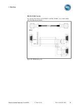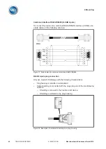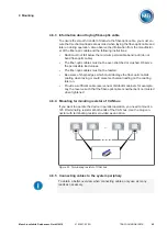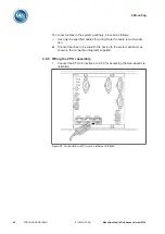
4 Mounting
Maschinenfabrik Reinhausen GmbH 2016
41
5163667/00 EN
TRAFOGUARD® ISM®
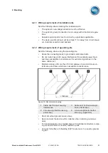
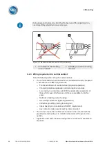
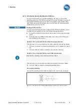
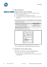
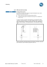
Wiring information
Note this procedure for the wiring:
ü
To obtain a better overview when connecting cables, only use as many
leads as necessary.
ü
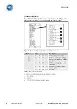
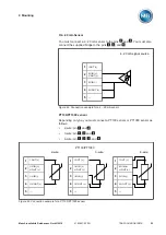
Note the connection diagram.
ü
Use only the specified cables for wiring. Note the cable recommenda-
tion.
ü
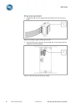
Wire the leads to the system periphery [
1.
Strip insulation from leads and wires.
2.
Crimp stranded wires with wire end sleeves.
Cable recommendation
Please note the following recommendation from Maschinenfabrik Reinhau-
sen when wiring the device.
Excessive line capacitance can prevent the relay contacts from breaking the
contact current. In control circuits operated with alternating current, take into
account the effect of the line capacitance of long control cables on the func-
tion of the relay contacts.
If you want to route Ethernet connections starting from a control cabinet or
building, we recommend the use of fiber-optic cables (in accordance with
the recommendation from IEC 61850-90-4).
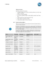
Cable
Assembly
Cable type
Conductor cross-
section
Max. length
Power supply (exter-
nal)
OT1205, G1
PULS
QS2.341
Unshielded
1.5 mm²
-
Power supply (internal,
24 VDC)
CPU, DIO,
AIO, MC,
SW
Unshielded
1.5 mm²
-
Voltage measurement
UI 1, UI 1-1,
UI 3
Shielded
2.5 mm²
-
Current measurement
UI 1, UI 1-1,
UI 3
Unshielded
4 mm²
-
Signal inputs
DIO 28-15,
DIO 42-20
Shielded
1.5 mm
2
400 m (<25 Ω/km)
Signal outputs*
DIO 28-15,
DIO 42-20
Shielded
1.5 mm
2
-
Signal inputs
AIO 2, AIO
4
Shielded
1 mm
2
400 m (<25 Ω/km)
Signal outputs
AIO 2, AIO
4
Shielded
1 mm
2
-
RS232, RS485 SUB-D
CPU I
Shielded
0.25 mm
2
25 m
4.6.1
Summary of Contents for TRAFOGUARD ISM
Page 1: ...Monitoring System TRAFOGUARD ISM Operating Instructions 5163667 00 EN ...
Page 222: ......
Page 223: ......

