4 Mounting
Maschinenfabrik Reinhausen GmbH 2016
62
5163667/00 EN
TRAFOGUARD® ISM®
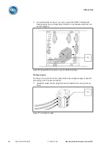
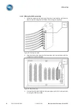
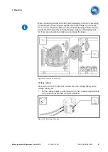
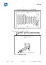
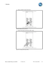
2.
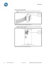
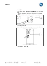
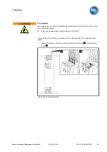
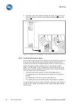
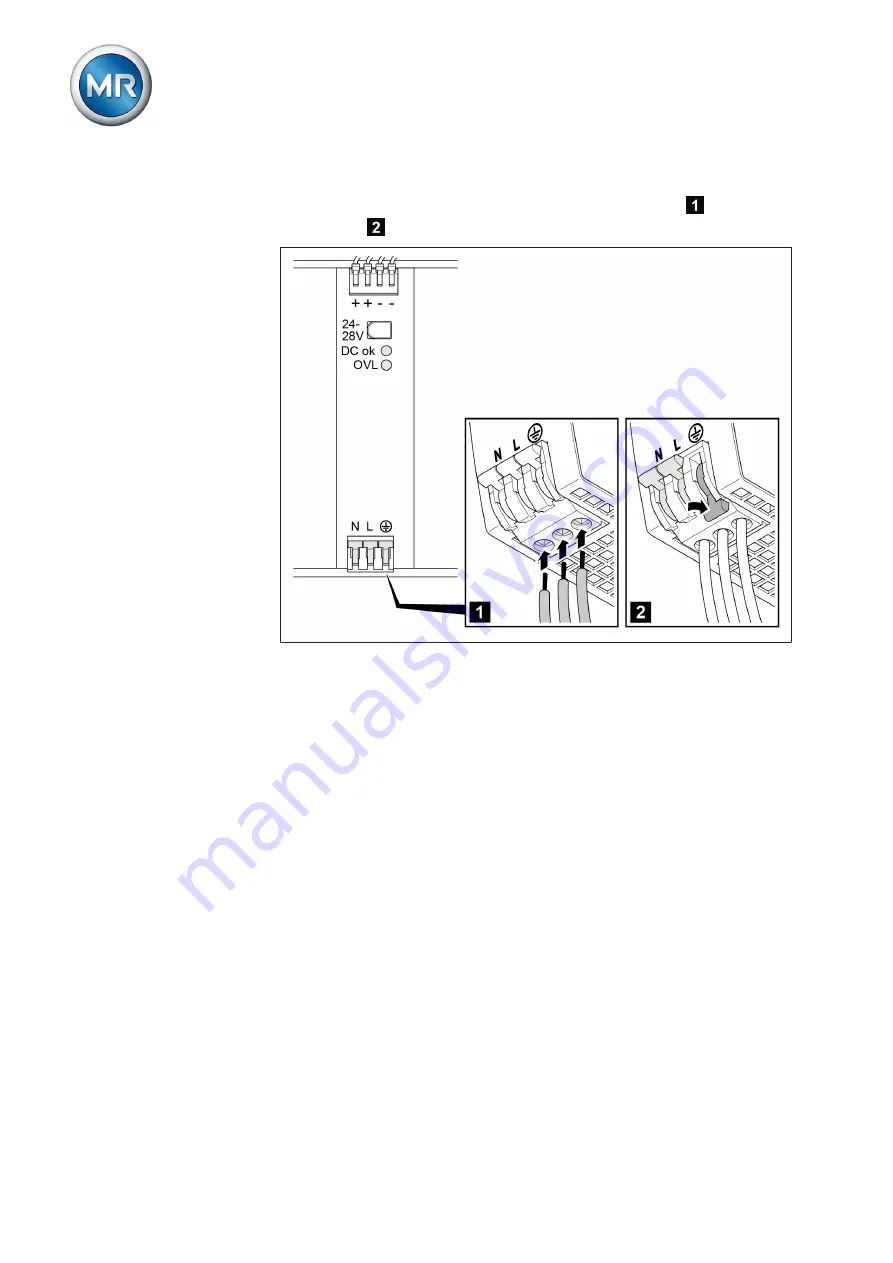
Insert the guides of the neutral conductor (N), phase conductor (L) and
protective conductor into the corresponding connections
and close
the lever
.
Figure 61: Inserting the neutral conductor, phase conductor and protective conductor
Connecting the power supply
You may only connect the device to circuits with an external overcurrent pro-
tection device and an isolating device with all poles disconnected so the
equipment can be fully de-energized if required (service, maintenance etc.).
Suitable equipment includes isolating devices in accordance with IEC
60947-1 and IEC 60947-3 (e.g. circuit breaker). When selecting the circuit
breaker type, note the properties of the relevant circuits (voltage, maximum
currents). Please also note the following:
▪
It must be easy for the operator to access the isolating device
▪
The isolating device must be labeled for the device and circuits to be
isolated
▪
The isolating device must not be part of the power line
▪
The isolating device must not interrupt the main protective conductor
You must connect the power supply circuit with a conductor cross-section of
at least 2.5 mm
2
(AWG 13) and protect it with a C6A or B6A type miniature
circuit breaker.
4.6.12
Summary of Contents for TRAFOGUARD ISM
Page 1: ...Monitoring System TRAFOGUARD ISM Operating Instructions 5163667 00 EN ...
Page 222: ......
Page 223: ......

