4 Mounting
Maschinenfabrik Reinhausen GmbH 2016
34
5163667/00 EN
TRAFOGUARD® ISM®
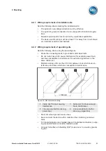
Minimum distances
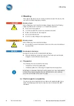
NOTICE
Damage to the device due to overheating!
Insufficient circulation of ambient air can result in damage to the device.
► Keep the ventilation slots clear.
► Ensure sufficient distance to neighboring components.
► Only mount device in horizontal position (ventilation slots are at the top
and bottom).
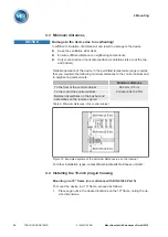
Reliable operation of the device in the permitted temperature range requires
that you maintain the following minimum distances to the control cabinet and
to neighboring components:
Minimum distance
To the floor of the control cabinet
88.9 mm (3.5 in)
Corresponds to 2 RU
To the roof of the control cabinet
Between assemblies on the bus bar and
assemblies on the remote cap rail
Table 5: Minimum distances in the control cabinet
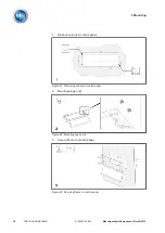
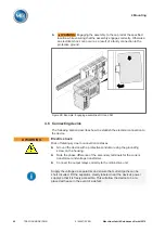
Figure 18: Example depiction of the minimum distances in a control cabinet
For other installation types, contact Maschinenfabrik Reinhausen GmbH.
Installing the 19-inch plug-in housing
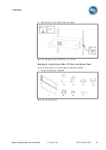
Mounting in a 19" frame (in accordance with DIN 41494 Part 5)
To mount the device in a 19" frame, proceed as follows:
1.
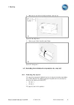
Place cage nuts in the desired locations on the 19" frame, noting the de-
vice dimensions.
4.3
4.4
Summary of Contents for TRAFOGUARD ISM
Page 1: ...Monitoring System TRAFOGUARD ISM Operating Instructions 5163667 00 EN ...
Page 222: ......
Page 223: ......

