background image

Recirculating cooler

Chiller

5

Section II Transportation & Installation

2.1 Transportation Requirements

Please take appropriate safety measures for the transportation of the goods and
shall pack the goods according to the general way.

1) The cargo shall be fixed and protected against shock and violent vibration.

2) Necessary measures should be taken to prevent moisture, rain and theft.

3) Inverted, inclined and horizontal are prohibited.

2.2 Unpacking

Your chiller is shipped in a special carton. Retain the carton and all packing
materials until the unit is completely assembled and working properly. Set up and
run the unit immediately to confirm proper operation. Beyond one week, your unit
may be warranty repaired, but not replaced. If the unit is damaged or does not
operate properly, contact the transportation company, file a damage claim, then
contact the company where your unit was purchased.

2.3 Package Contents

1) Chiller
2) User Operating Manual
3) Power Core
4) Certificate of Quality and Packing List
5) Standard Output and Accessories

2.4 Installation Instruction

The unit shall be installed indoor with good environment. The principles are as
following:

Summary of Contents for CWN-1.6KW

Page 1: ...User Operating Manual Recirculating Coolers Chiller Original Instructions 3 Hagavish st Israel 58817 Tel 972 3 5595252 Fax 972 3 5594529 mrc mrclab com MRC 9 22...

Page 2: ...ou for a long time First of all we thanks for the trust to us This operating manual has been designed to help you understanding the principles of operation and possibilities of chillers For optimum ut...

Page 3: ...8 3 1 Preparations before operation 8 3 2 Controller Panel 10 3 3 Advanced Application Mode 12 3 4 Common Alarms 14 3 5 Hardware interface Optional 19 Section IV Operation guide 19 4 1 Switching on 2...

Page 4: ...turn off the chiller and disconnect the mains cable from the power supply before performing any service or maintenance procedures or before moving the chiller 10 Always empty the bath before moving t...

Page 5: ...CT medical physiotherapy chiller production test chiller precision grinder computer numerical control machine machining center laser equipment etc This chiller is an integral product with parts such a...

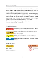
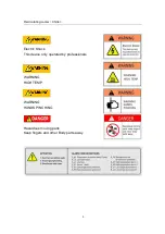
Page 6: ...Recirculating cooler Chiller 3 Electric Shock This device only operated by professionals WARNING HIGH TEMP WARNING HANDS PINCHING Hazardous moving parts Keep fingers and other Body parts away...

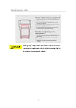
Page 7: ...Recirculating cooler Chiller 4 Emergency stop button should be included on the customers equipment which chillers supporting for to ensure the operator s safety...

Page 8: ...special carton Retain the carton and all packing materials until the unit is completely assembled and working properly Set up and run the unit immediately to confirm proper operation Beyond one week y...

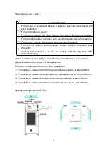
Page 9: ...sprayer sulfide contained used frequently 7 Ambient temperature 5 to 30 C relative humidity less than 80 non condensing As for convenience and safety of maintenance and installation keep certain dist...

Page 10: ...transit Install the unit in the proper position and ensure it is stable and safe then install the external circulating loop pipelines Please ensure correct collection of the external circulating wate...

Page 11: ...stance shall not be bigger than 0 1 Electric power supply capacity not less than 1 5times of unit power for single chiller 3 1 4 reservoir liquid injection reservoir liquid should be injected for the...

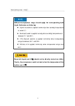
Page 12: ...s under 5 Deionized water is applied usually when working temperature is between 5 and 80 15 Glycerin solution is applied commonly when temperature range is between 80 and 90 Silicone oil is applied c...

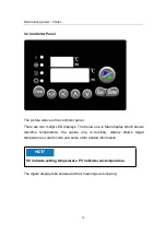
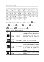
Page 13: ...it LED displays The below one is Main display which shows real time temperature the upside one is Auxiliary display shows target temperature or alarm code and some other related information SV indicat...

Page 14: ...flashes Low water level alarm No water flow alarm Protection delay alarm High temperature and low temperature alarm Cooling indicator Green light on Cooling system working indicator Heating indicator...

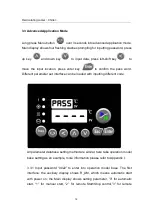
Page 15: ...he pass word Different parameter set interface can be loaded with inputting different code All parameter database setting method are similar here take operation model base setting as an example more i...

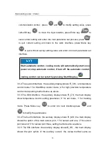
Page 16: ...hird interface the auxiliary display shows R_CS the main display show temperature control setting parameter 0 for set mode 1 for tracking mode Press Menu key to enter into next interface press and to...

Page 17: ...show _END which means the end of parameter set 3 4 Common Alarms Start up Delay alarm E_DL The unit will not start cooling until 3 minutes delay protection is finished In power on state when the inte...

Page 18: ...er s external water circulation begins to import water In standby state the compressor won t start when press the compressor Start Stop key it will return to normal after water fulfilled In work state...

Page 19: ...lerting with buzzer beeps and the Auxiliary display shows E LF Check the pump running or not If pump not running the alarm can be cleared by turn on the pump except this reason check whether there is...

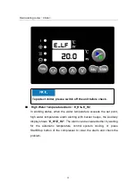
Page 20: ...t high water temperature alarm alerting with buzzer beeps the Auxiliary display shows E_H1 E_H2 The alarm can be cleared either by waiting for the automatic temperature control system cooling or press...

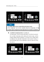
Page 21: ...mpressor protection Low Water Temperature Alarm E_L1 E_L2 In working status when the water temperature is less than the set point the low water temperature alarm alerting with buzzer beeps and the Aux...

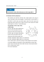
Page 22: ...on plug The definition of the 12 pins of the aviation plug Pin 1 2 water flow signal output which function with normal water flow and disconnect with abnormal water flow Pin 3 4 water level signal out...

Page 23: ...rn on the power switch Then the unit begins to initializing Once finished the unit enters standby mode with a buzzer beep 4 1 3 Start pump and compressor as per manual instruction 4 1 4 Check the fluc...

Page 24: ...ature of the reservoir in a constant value T_00 via PID algorithm The unit under this mode can also work turned to the Start Stop mode by setting R_CS and R_CM parameters please refer to part 3 3 for...

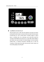
Page 25: ...mperature of the reservoir is higher than T_00 T_01 compressor starts to cooling and it stops until the temperature lower than T_00 T_01 If set T_00 20 and T_01 5 then the unit will control the temper...

Page 26: ...extra temperature sensor which can sense the temperature of the ambient or user s equipment Please refer to Part 3 3 for detailed setting method It is not standard configuration just optional for cust...

Page 27: ...rameters are slightly different if cooling power is different When connecting with different loading units the control parameters are usually different PID parameters can be adjusted via circulator fo...

Page 28: ...c leakage protection and power switch empty and dry the water reservoir and pump 4 6 4 After long time usage the pump should be opened to check and change the worn out parts when water flow and pressu...

Page 29: ...decrease of the rotor Solution Cut off the power supply open the cover board of the chiller and pull out the rubber gasket rotate the rotor for a while by a straight screwdriver then the pump can be r...

Page 30: ...Daily Maintenance Set up a periodic schedule to clean the removable air filter at least monthly Tap water and mild detergent is sufficient to clean filter material Frequency of cleanings depends on th...

Page 31: ...0 01 9 99 5 Tracking temperature T_11 Setting deviation temperature tracking mode 99 9 99 9 2 Temperature correction database password 0011 long menu key enter the password interface input 0011 to en...

Page 32: ...mperature control set option 0 set mode 0 1 tracking mode Main sensor option R_MS Main temperature sensor port option 1 sensor port 1 1 2 sensor port 2 3 sensor port 3 Auxiliary sensor option R_SS Aux...

Page 33: ...mperature 5 PID proportional item 0 1 999 9 5 Second PID 2_PI Low temperature 5 PID integral item 0 9999S 0 no action 120 Second PID 2_PD Low temperature 5 PID differential term 0 9999S 0 no action 30...

Page 34: ...erature alarm C_PL 1 C_PH C_PH High temperatu re alarm 2 E_H2 The second point of the user defined high temperature alarm E_H1 1 C_PH C_PH Low temperatu re alarm 1 E_L1 The first point of the user def...

Page 35: ...alarm 4 E_L2 alarm 5 E_S1 alarm 6 E_ S2 alarm 7 E_ S3 alarm 8 E_CE alarm 9 E_ PL alarm 10 E_PH 11 0 Warning port 2 E_O2 Alarm output port 2 configuration output port 6 0 No alarm 1 E_H1 alarm 2 E_H2 a...

Page 36: ...e No quit when the temperature higher than E_L2 back to original work mode Water level alarm 2S flash E_LS Current temperature Stop heating cooling quit at normal water level and back to original work...

Page 37: ...work mode Delay 2S flash E_dL Countdown No quit with countdown Communication 2S flash E_CE Current temperature No quit with countdown Under lower limit of the unit temperature 0 5S flash E_PL Current...

Reviews: