58
Blaster’s Ranger II Lt Operations Manual - Edition 1.1
Lt
The origin of the coordinate system can be set in a similar method. Point the reticle to point were the operator requests the coordinate
origin to be (0,0). This will be the reference point for all of the measurements. After the origin is set, the orientation of the axes must be
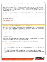
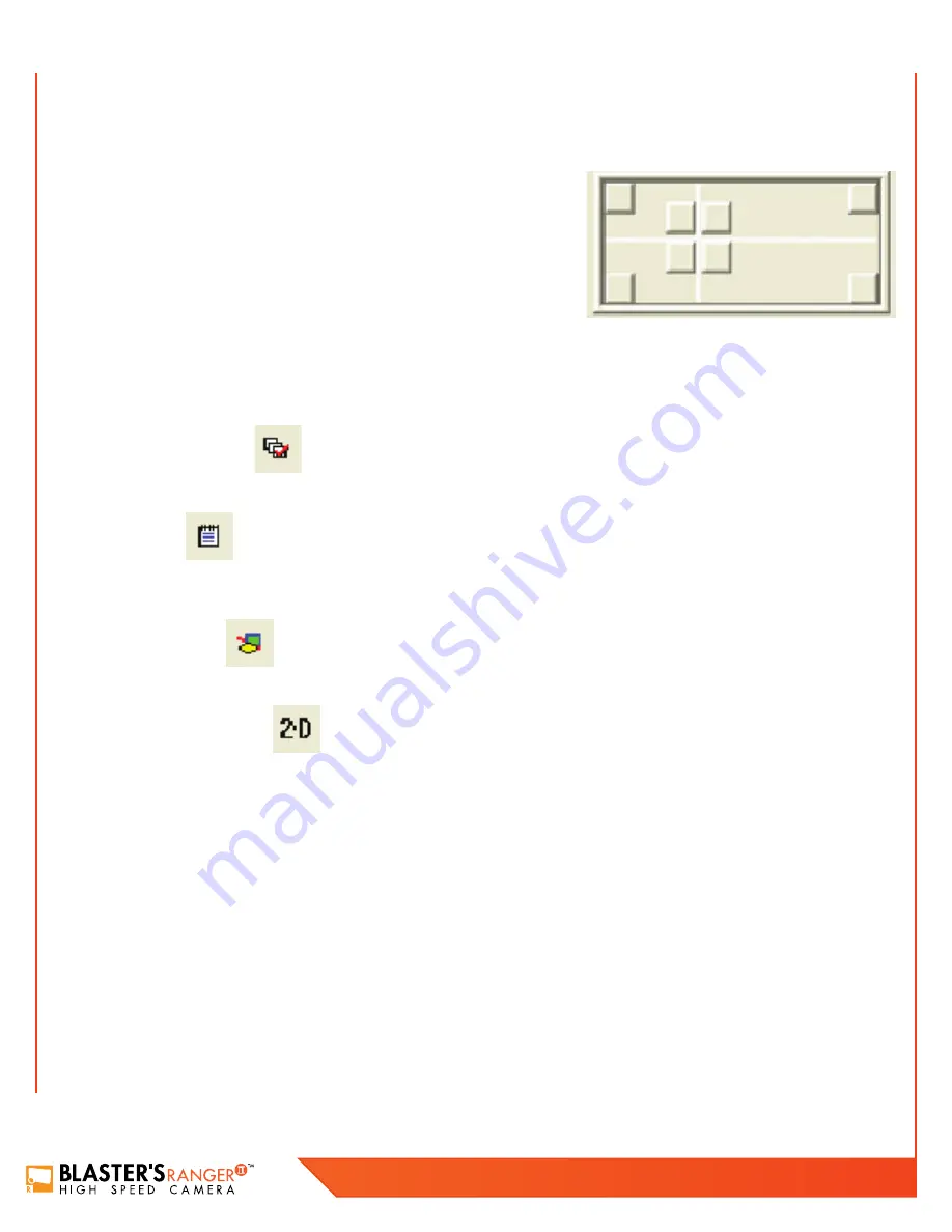
set. As shown below, each of the buttons in the picture will set the orientation of the axes.
Each of the corner buttons will set the origin of the coordinate system in the
respective corner. The positive orientation of the two axes will be along the edge
of the frame. For example, the top left button will set positive X direction to the
right and the positive Y direction down while the bottom right button will set the
positive X direction to the left and the positive Y direction up. The four buttons
around the reticle will set the positive orientation around the button pressed from
the reticle position. If the orientation of the X axis is not horizontal, from the origin
of the coordinate system place the reticle on the horizontal line and then click Set
X Direction. Once the Origin and positive axes are set, the user MUST click
Apply
Origin and Tilt >>
button. After the button is clicked, the pixels (origin) will be displayed as well as the degrees (tilt).
The user MUST then click
Apply
to set the changes and then
Close
. The user can then remove calibrations if they were made in error.
8.2.3 Display Layers
This menu allows the user to change which layers are displayed and the information displayed on the screen.
8.2.4 Notes
This will allow the user to make notes on the video file. The area labeled Video Notes is information about the displayed frame
while the Global Notes area pertains to the whole video.
8.2.5 Annotations
The tab allows the user to draw and place text on the video frame.
8.2.6 Feature Tracking
This tab will allow the user to track a point on the video.
In the top left of the tab,
Feature Tracking
must be enabled. If user can not change any other part of the menu structure, click on
Enable
.
The user needs to decide whether a
Manual
or
Automatic mode
will be used to track an object.
In
Manual Mode
, the operator will manually select each and every point that will be used in the calculations. In
Manual Mode
, less video
manipulation (Image Processing) is required because the human eye can distinguish the difference when tracking an object better than a
computer algorithm. The operator can switch between
Manual
and
Automatic
while tracking a single object. When the user is in
Manual
mode
, the user can click on
Add
and add a feature that can be used to track an object. This is the simplest way to track. Click to place
the reticle on the object the user wishes to track and click
Set Point
. This needs to be done in every frame the operator wishes to track.
This can be a long and tedious task if a lot of frames need to be
In
Automatic Tracking
, a feature can be added just as in Manual tracking but now the user needs to define a region of the video that
Summary of Contents for Blaster's Ranger II Lt
Page 7: ...T 1 613 545 0466 F 1 613 542 8029 www mrel com 1 Chapter 1 Introduction ...
Page 10: ...4 Blaster s Ranger II Lt Operations Manual Edition 1 1 Lt ...
Page 11: ...T 1 613 545 0466 F 1 613 542 8029 www mrel com 5 Chapter 2 Hardware ...
Page 15: ...T 1 613 545 0466 F 1 613 542 8029 www mrel com 9 Chapter 3 Getting Started ...
Page 19: ...T 1 613 545 0466 F 1 613 542 8029 www mrel com 13 Chapter 4 FasMotion ...
Page 29: ...T 1 613 545 0466 F 1 613 542 8029 www mrel com 23 Chapter 5 Recording ...
Page 47: ...T 1 613 545 0466 F 1 613 542 8029 www mrel com 41 Chapter 6 Using the Web App ...
Page 55: ...T 1 613 545 0466 F 1 613 542 8029 www mrel com 49 Chapter 7 Field Operations ...
Page 57: ...T 1 613 545 0466 F 1 613 542 8029 www mrel com 51 ...
Page 74: ...68 Blaster s Ranger II Lt Operations Manual Edition 1 1 Lt ...
Page 77: ...T 1 613 545 0466 F 1 613 542 8029 www mrel com 71 ...


