USER MANUAL SWG
Page 42 of 129
4.4.
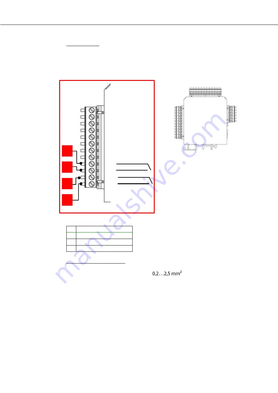
Alarm outputs
Hardware side:
Every IO module has two alarm outputs. The position of the alarm-outputs are
marked with the red labels.
Reference:
1
1 Alarm Relay +
2
1 Alarm Relay -
3
2 Alarm Relay +
4
2 Alarm Relay -
Information for connection:
Conductor cross section:
Relays-type:
Normally open
Voltage supply:
max. 24 VDC
1
2
3
4
Summary of Contents for SWG 100 SYNGAS
Page 1: ...SWG 100 SYNGAS USER MANUAL ...
Page 12: ...USER MANUAL SWG Page 12 of 129 11 H3PO4 inlet G1 8 inner thread ...
Page 24: ...USER MANUAL SWG Page 24 of 129 ...
Page 32: ...USER MANUAL SWG ...
Page 63: ...USER MANUAL SWG Page 63 of 129 Detail A Alarm Relais ...
Page 89: ...USER MANUAL SWG Page 89 of 129 8 3 Description of the analyser 1 1 1 1 2 ...
Page 99: ...USER MANUAL SWG Page 99 of 129 ...
Page 110: ...USER MANUAL SWG Page 110 of 129 12 Appendix ...
Page 114: ...USER MANUAL SWG Page 114 of 129 ...
Page 116: ...USER MANUAL SWG Page 116 of 129 Positions of the components 3 4 ...
Page 127: ...USER MANUAL SWG Page 127 of 129 ...
Page 129: ...USER MANUAL SWG Page 129 of 129 ...


