USER MANUAL SWG
Page 76 of 129
7.
Operating the analyser
0013
This chapter has the follow structure:
•
In the first part it will be explained, how to start the analyser and the selftest
menu.
•
Part three shows the submenu, which are listed at the EXTRA menu.
•
Part four shows the store menu.
7.1.
General process of the measurement cycle
Self-Test
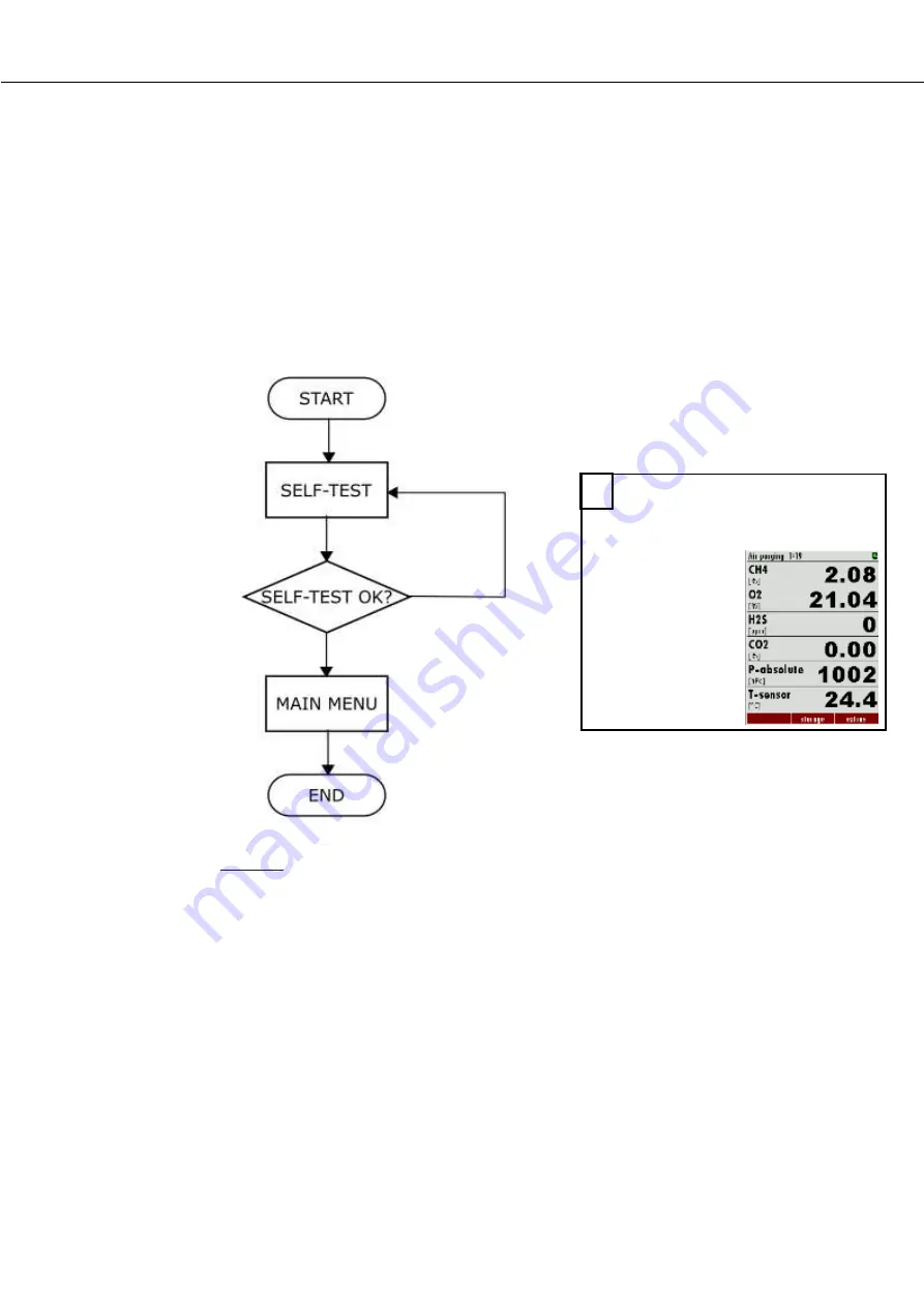
The first menu to be displayed after Power-On is the self-test menu. The analyser
won't leave this menu before all sub-systems will be connected and the gas cooler
(option) has reached the target operation temperature.
During the self-test phase
•
the gas pump is switched off
•
all analog outputs will deliver 2mA
•
all alarm outputs will have alarm status (open contacts)
Usually the self-test will be left automatically as soon as all conditions for
measurement are satisfied. Then the first zeroing will be started.
If one of the internal RS485 bus participants are issuing alarm (faulty) status, the
user can still leave the self-test manually by pressing F2='forward' (PIN code
requested), even if not all sub-systems or the gas cooler are ready.
2
Main menu measurement (see in
this chapter)
Summary of Contents for SWG 100 SYNGAS
Page 1: ...SWG 100 SYNGAS USER MANUAL ...
Page 12: ...USER MANUAL SWG Page 12 of 129 11 H3PO4 inlet G1 8 inner thread ...
Page 24: ...USER MANUAL SWG Page 24 of 129 ...
Page 32: ...USER MANUAL SWG ...
Page 63: ...USER MANUAL SWG Page 63 of 129 Detail A Alarm Relais ...
Page 89: ...USER MANUAL SWG Page 89 of 129 8 3 Description of the analyser 1 1 1 1 2 ...
Page 99: ...USER MANUAL SWG Page 99 of 129 ...
Page 110: ...USER MANUAL SWG Page 110 of 129 12 Appendix ...
Page 114: ...USER MANUAL SWG Page 114 of 129 ...
Page 116: ...USER MANUAL SWG Page 116 of 129 Positions of the components 3 4 ...
Page 127: ...USER MANUAL SWG Page 127 of 129 ...
Page 129: ...USER MANUAL SWG Page 129 of 129 ...


