LambdaDriver 400 & 800
ML46430, Rev. 07
October 2004
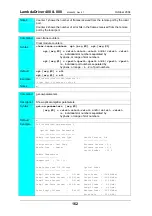
[arg #0] =
Slot number of the local transponder
[arg #1] =
1
(for Transponder 1) or
2
(for Transponder 2)
opt.[arg #2] = rlb
(RLB mode)
opt.[arg #3] = l
(enable loopback mode)
Hardware Control
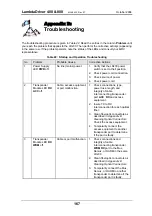
The procedure for configuring the TM2-SFP transponders in the local and remote LDx00s so that
they can be controlled by hardware is as follows:
Local
6. Insert the Transponder in the
local
LDx00.
5. With the aid of
on page
, locate Jumper
JP4
(if Transponder
1
was chosen)
or Jumper
JP5
(if Transponder
2
was chosen) on the Transponder module and, using
on page
, set it to the position
LOOP
.
TM-DXFP
1. Place the Transponder to be installed in the local LDx00 on a flat clean stable surface.
2. Choose
Transponder
1
or
2
as the local transponder to be used in the RLB test.
3. With the aid of
on page
, locate DIP switch
SW1
(if Transponder
1
was
chosen) or DIP switch
SW2
(if Transponder
2
was chosen) on the Transponder module.
4. Set the DIP switch according to the appropriate row (number 2 onwards) of
page
5. With the aid of
on page
, locate Jumper
JP4
(if Transponder
1
was chosen)
or Jumper
JP5
(if Transponder
2
was chosen) on the Transponder module and, using
on page
, set it to the position
NORMAL
(factory default).
Remote
1. Place the Transponder to be installed in the remote LDx00 on a flat clean stable surface.
2. Choose the remote transponder having the same number as the local transponder.
3. With the aid of
on page
, locate DIP switch
SW1
(if Transponder
1
was
chosen) or DIP switch
SW2
(if Transponder
2
was chosen) on the Transponder module.
4. Set the DIP switch according to the appropriate row (number 2 onwards) of
page
6. Insert the Transponder in the
remote
LDx00.
7. Ensure that the
remote
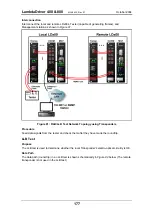
TM2-SFP transponder is connected to the
local
TM2-SFP
transponder with intra- and inter-LDx00 cabling.
3. Set the DIP switch toggle 6 to the
ON
position (for configuration control by software) as
shown in row 6 of
Software Control
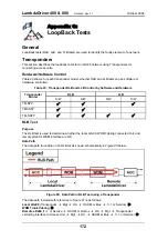
The procedure for configuring the TM-DXFP transponders in the local and remote LDx00s so that
they can be controlled by software is as follows:
Local
1. Place the Transponder to be installed in the local LDx00 on a flat clean static-free stable
surface.
2. With the aid of
locate DIP switch
SW1
on the Transponder.
4. Insert the Transponder in the
local
LDx00.
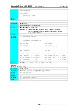
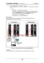
5. At the management station, invoke the CLI command:
set-transponder-lb [arg #0] [arg #1] opt.[arg #2] opt.[arg
#3]
where,
[arg #0] =
Slot number of the local transponder
[arg #1] =
1
(number of the transponder in the slot)
175


