background image

LambdaDriver 400 & 800


ML46430, Rev. 07


October 2004 

LD400: 

With Mounting 
Brackets 
Without Mounting 
Brackets 

LD800: 

With Mounting 
Brackets 
Without Mounting 
Brackets 

 
482 x 89 or 2U

33

 x 324 mm


3

 (19 x 3.5 or 2U x 12.8 in


3

 
443 x 89 or 2U x 324 mm


3

 (17.5 x 3.5 or 2U x 12.8 in


3


482 x 200 or 4.5U x 267 mm


3

 (19 x 7.8 or 4.5U x 10.5 in


3

 
446 x 200 or 4.5U x 267 mm


3

 (17.5 x 7.8 or 4.5U x 10.5 in


3

Weight (with full load) 

LD400: 
LD800: 

 
10 kg (22 lb) 
20 kg (44 lb) 

Mounting 

Desktop or 19-inch (482 mm) rack per EIA RS-310C standard 


33

 1U = 1¾ inch or 44.45 mm 


203


Summary of Contents for LambdaDriver 400

Page 1: ...LambdaDriver Wavelength Division Multiplexer Models 400 and 800 User Manual MRV Communications Inc URL http www mrv com...

Page 2: ...RV reserves the right to make changes to any technical specifications in order to improve reliability function or design MRV reserves the right to modify the equipment at any time and in any way it se...

Page 3: ...yms 16 Safety Requirements 18 Before Installing 18 Before Powering On 18 During Operation 19 Servicing 19 Chapter 1 Overview 20 Function 20 Advantages 20 Features 20 Application 21 Installation 21 Ope...

Page 4: ...38 Overview 38 Features 38 Models 38 Layout 39 Product Specification 40 1 1 Redundancy Module 44 Overview 44 Features 44 Layout 45 Product Specification 46 OADM Module 48 Overview 48 Features 48 Layou...

Page 5: ...dant Power Supply Module Optional 66 Overview 66 Features 66 Fan Module 66 Blank Panel Module 67 Overview 67 Layout 67 Channels 67 CWDM 67 DWDM 68 Chapter 2 Applications 69 General 69 Point to Point N...

Page 6: ...ata Flow 79 CO LDx00 79 Left BO LDx00 79 Right BO LDx00 79 Multipoint Network Topologies 81 Regular Multipoint 81 Scope 81 Hardware 81 Cabling 81 Data Flow 81 Repeated Channel Use Multipoint 82 ESCON...

Page 7: ...9 ESCON Module 111 Mounting 113 Chassis 113 Modules 113 Cabling 115 Module to Module 115 Access Ports 132 Management Ports 133 Power Line Connection 134 Chapter 4 Startup Setup and Operation 135 Start...

Page 8: ...ownloading165 General 165 Requirements 165 Interconnection 165 Setup 165 Procedure 165 Appendix B Troubleshooting 167 Appendix C LoopBack Tests 172 General 172 Transponders 172 Hardware Software Contr...

Page 9: ...Cable Wiring 184 Appendix E Cleaning Optical Connectors 186 General 186 Tools and Equipment 186 Procedure 186 Appendix F Modem Setup and Installation 187 General 187 Requirements 187 LDx00 Side 187 M...

Page 10: ...d to End Total Redundancy 192 Ring with Inclusive End to End Total Redundancy 193 Point to Point with Exclusive End to End Total Redundancy 194 Ring with Exclusive End to End Total Redundancy 195 Poin...

Page 11: ...le Layout 67 Figure 24 Regular Point to Point with up to 8 Full Duplex Channels 70 Figure 25 Link Protected Point to Point with up to 8 Full Duplex Channels 71 Figure 26 Single Fiber Point to Point wi...

Page 12: ...or between LDx00s 126 Figure 65 ESCON to ESCON Cabling between LDx00s 126 Figure 66 Pre Amplifier OA to Demux Cabling in LDx00 127 Figure 67 Pre Amplifier OA to Single Interface OADM Cabling in LDx00...

Page 13: ...92 Point to Point with Inclusive End to End Total Redundancy 193 Figure 93 Ring with Inclusive End to End Total Redundancy 194 Figure 94 Point to Point with Exclusive End to End Total Redundancy 195 F...

Page 14: ...g 104 Table 10 JP1 Jumper Positioning 105 Table 11 JP2 Jumper Positioning 106 Table 12 JP4 and JP5 Jumpers Positioning 106 Table 13 DIP Switch SW1 or SW2 Setting of TM SFP or TM2 SFP Transponder Modul...

Page 15: ...atures advantages architecture components etc Chapter 2 Applications presents typical networks built round the LDx00s Chapter 3 Installation shows how to mount network connect and hardware configure t...

Page 16: ...e represents information provided by the system Courier Bold This typeface represents information provided to the system Italics This typeface is used for emphasis Enter This format represents the key...

Page 17: ...OSC Optical Service Channel PLL Phase Locked Loop RARP Reverse ARP RI Ring Ignore RLB Remote LoopBack RMON Remote MONitoring RTS Request To Send RxD Receive Data SDH Synchronous Digital Hierarchy SFP...

Page 18: ...space in a 19 inch rack or Flat stable non conductive static free surface Before Powering On Blank Panels Ensure that vacant slots of the LDx00 are covered with Blank Panels This protects the user aga...

Page 19: ...t One end is terminated in an IEC 320 attachment plug the other in a NEMA 5 15P plug The power cord to be used with a 230 Volt AC configuration must be a minimum type SJT SVT 18 3 rated 250 Volts AC 1...

Page 20: ...on Features Metro access and campus network applicability Handles multiple protocols concurrently Supports mixed data speeds Transparent to network topology and protocols Point to point ring star and...

Page 21: ...n Web based element manager for configuring and monitoring a single device in a real network environment MegaVision Demo is a comprehensive simulator of the MegaVision real device network management a...

Page 22: ...odules and up to two pluggable power supplies and contains WDM support functionality It can support various combinations of network modules to offer a wide range of applications Features Six for LD400...

Page 23: ...nd get card wdm power described on page 158 Y cable connectivity enables terminal equipment without redundant interfaces to be integrated into redundancy protection WDM networks see Appendix I Redunda...

Page 24: ...ength in the range 1470 to 1610 SFP Access port Fixed WDM ports fitted with Mu MiniSC connectors SFF 8472 Digital diagnostics Standard G 652 G 655 fibers 2 TM DSFP xx DWDM technology Data Rate of chan...

Page 25: ...LambdaDriver 400 800 ML46430 Rev 07 October 2004 Layout Figure 3 TM SFP Single Transponder Module Layout Figure 4 TM2 SFP Dual Transponder Module Layout 25...

Page 26: ...LambdaDriver 400 800 ML46430 Rev 07 October 2004 Figure 5 TM DXFP 10 Gbps Transponder Module Layout 26...

Page 27: ...Fiber Length max Outband TM SFP to TM SFP 100 km 62 1 mi TM2 SFP to TM2 SFP Per the local TM2 SFP WDM SFP transmitter output power remote TM2 SFP WDM SFP receiver sensitivity and power loss due to oth...

Page 28: ...al TM2 SFP WDM SFP receiver sensitivity and power loss due to other elements in the signal path see Rule 17 page 98 The cable length is the smaller of the fiber lengths for the WDM TX Port and WDM RX...

Page 29: ...Purpose Connection to access unit transmit port or ESCON SFP TX port Cable Fiber Length max Per the access unit output power and transponder access SFP receiver sensitivity see Rule 16 page 97 Cable T...

Page 30: ...Outband 100 km 62 1 mi Inband Transpopnder to Mux or OADM in same LDx00 1 m 3 ft Local Mux or OADM to Remote Mux or OADM between two LDx00s 100 km 62 1 mi Cable Type Singlemode 9 125 m Cable Connector...

Page 31: ...e Port Purpose Connection to access equipment transmit port Cable Fiber Length max XFP 10GD LR 10 km XFP 10GD SR 2 km Cable Type Singlemode 9 125 m Cable Connectors Per the SFP usually LC APD Overload...

Page 32: ...e and use optics only for their operation Figure 24 Figure 25 Figure 28 and Figure 30 shows how Mux modules can be applied Features No electric power grounding or protection needed No opto electric tr...

Page 33: ...depends on whether the technology is CWDM or DWDM and on channel bandwidth Data Rate Range see Transponder Product Specification If an ESCON or GM27 is connected to a Mux refer to ESCON Product Specif...

Page 34: ...well as DWDM Demux modules are available The modules are passive and use optics only for their operation Figure 24 Figure 25 Figure 26 Figure 28 Figure 29 and Figure 30 shows how Demux modules can be...

Page 35: ...depends on whether the technology is CWDM or DWDM and on channel bandwidth Data Rate Range see Transponder Product Specification If an ESCON or GM29 is connected to a Demux refer to ESCON Product Spe...

Page 36: ...ET station can be connected to the Ethernet 10 100Base TX or 100Base FX port A 100Base FX port can be connected to a Service or 1 1 Redundancy module Figure 24 to Figure 31 show how Management modules...

Page 37: ...onal Connection to Service MGT TX port or 1 1 MGT TX port Receiver Sensitivity 37 to 40 dBm Operating Wavelength 1310 nm Cable Length max 1 m 3 ft Cable Type Singlemode 9 125 m Cable Connector SC ETH...

Page 38: ...ics only for its operation Service modules are available in two models described in the section Models on page 38 The EM800 DSRV model consists of two Service modules on one physical card that is just...

Page 39: ...LambdaDriver 400 800 ML46430 Rev 07 October 2004 Layout Figure 9 Single Service Module Layout Figure 10 Dual Service Module Layout 39...

Page 40: ...e Singlemode 9 125 m Cable Connector MiniSC MU MGT TX Port Management Transmit Port Purpose Connection to Management ETH 1 RX or ETH 2 RX port Power Attenuation 0 8 to 1 dB Cable Length max 1 m 3 ft C...

Page 41: ...the smaller of the fiber lengths for the IN Port and OUT Port Cable Type Singlemode 9 125 m Cable Connector SC Mounting Handle ejector extractor Posidrive screws two Physical Dimensions W x H x D 26...

Page 42: ...ice OUT port Power Attenuation 0 8 to 1 dB Cable Fiber Length max Per the remote Transponder power budget which depends on whether the technology is CWDM or DWDM and on channel bandwidth Data Rate Ran...

Page 43: ...to 1 dB Cable Length max 1 m 3 ft Cable Type Singlemode 9 125 m Cable Connector MiniSC MU MGT 2 RX Port Management 2 Receive Port Purpose Connection to Management ETH 1 TX or ETH 2 TX port Power Atte...

Page 44: ...The 1 1 Redundancy module is an interface for two fiberoptic cables for carrying identical data The cables backup each other The same information is transmitted on both fibers Normally the data on the...

Page 45: ...LambdaDriver 400 800 ML46430 Rev 07 October 2004 Layout Figure 11 1 1 Redundancy Module with Service Functionality Layout Figure 12 1 1 Redundancy Module without Service Functionality Layout 45...

Page 46: ...iSC MU MGT TX Port Management Transmit Port Purpose Connection to Management ETH 1 RX or ETH 2 RX port Cable Length max 1 m 3 ft Cable Type Singlemode 9 125 m Cable Connector MiniSC MU MGT RX Port Man...

Page 47: ...nology is CWDM or DWDM and on channel bandwidth Data Rate Range Cable Type Singlemode 9 125 m Cable Connector SC OUT S Port WDM Secondary Redundancy OSC Transmit Port Purpose optional Connection to 1...

Page 48: ...ables flexible and intelligent planning and provisioning of optical services while at the same time simplifying deployment and maintenance of optical networks In the dual fiber OADM module the COM por...

Page 49: ...LambdaDriver 400 800 ML46430 Rev 07 October 2004 Layout Figure 13 Single Interface OADM Module Layout Figure 14 Dual Interface OADM Module Layout 49...

Page 50: ...Port WDM Receive Port Purpose Connection to local Service MUX port local 1 1 MUX port remote Multiplexer OUT port or remote OADM OUT port Cable Length max 1 m 3 ft Cable Type Singlemode 9 125 m Cable...

Page 51: ...3 ft Cable Type Singlemode 9 125 m Cable Connector SC Power Attenuation WDM Port Attenuation dB Access Port Attenuation dB OADM Type Single Interface Dual Interface C1 C2 C3 C4 1 Channel 1 3 0 9 1 3...

Page 52: ...beroptic cabling There are three types OAs Booster Inserted at the beginning of the line In Line Inserted in the middle of the line Pre amplifier Inserted at the end of the line Figure 66 to Figure 73...

Page 53: ...iplexer Port Purpose Connection to Multiplexer OUT port or OADM OUT port Cable Length max Pre amplifier Per the formula in the footnote In Line 1 m 3 ft Booster 1 m 3 ft Cable Type Singlemode 9 125 m...

Page 54: ...wer Min Pre amplifier 5 to 25 dBm In line 5 to 20 dBm Booster 12 to 5 dBm Noise Figure for Gain 20 dB Typ 5 0 dB Max 5 5 dB Operating Wavelength 1528 to 1563 nm C band Input Output Isolation 30 dB min...

Page 55: ...e carried inband11 or outband12 LD400 ESCON modules can be installed in the LD400 in slots 1 to 5 Using just two LD400s Four pairs of ESCON modules can carry 16 ESCON channels inband using CWDM or DWD...

Page 56: ...pgrades and deviations since to change any one or more of the interface properties only the SFP and not the whole ESCON module needs to be replaced Figure 32 to Figure 35 show how ESCON multiplexer mo...

Page 57: ...ESCON equipment output TX Cable Fiber Length max 2 km 6561 ft Cable Type Singlemode 9 125 m Cable Connector LC SFP TX Port WDM Port Purpose Connection to Multiplexer TX port OADM ADD port or Transpond...

Page 58: ...reception synchronization status L 1 2 3 or 4 Access link status A WDM data reception synchronization status L WDM link status Mounting Handle ejector extractor Posidrive screws two Physical Dimensio...

Page 59: ...s the GM2 module with flexible connectivity to terminal equipment and minimizes cost of investment on upgrades and deviations since to change any one or more of the interface properties only the SFP a...

Page 60: ...LambdaDriver 400 800 ML46430 Rev 07 October 2004 Layout Figure 17 EM2009 GM2 Module Layout Figure 18 TM GM2 Module Layout 60...

Page 61: ...it output power and GM2 access SFP receiver sensitivity see Rule 16 page 97 Cable Type Per the SFP fiberoptic or copper Cable Connector Per the SFP TRUNK TX Port WDM Transmit Port Purpose Connection t...

Page 62: ...e Connection to Demultiplexer RX port or OADM DROP port Grid CWDM ITU T G 694 2 DWDM ITU T G 694 1 Receiver Sensitivity at TRUNK RX port EM2009 GM2 Per the SFP TM GM2 20 to 26 dBm APD Overload for GM2...

Page 63: ...the SFP LEDs A1 A2 Per port access data reception status L1 L2 Per port access link status A Trunk WDM data reception synchronization status L Trunk WDM link status Mounting Handle ejector extractor P...

Page 64: ...LambdaDriver 400 800 ML46430 Rev 07 October 2004 Layout LD400 Figure 19 LD400 AC Power Supply Module Layout LD800 Figure 20 LD800 AC Power Supply Module Layout 64...

Page 65: ...er Supply Module powers the LDx00 It is auto adaptive in the range 48 to 60 Vdc and can be backed up by a second power supply in the same LDx00 while equally sharing the output power load Features Hot...

Page 66: ...nd is backed up by the primary AC Power Supply Module Operates with the primary AC Power Supply Module in equal load sharing mode This mode prolongs their service life Features Hot swappable Pluggable...

Page 67: ...is used to cover any one of Slots 1 to 6 of the LD400 or Slots 1 to 12 of the LD800 when vacant Layout Figure 23 Blank Panel Module Layout Channels CWDM The LDx00 can be configured to support up to 4...

Page 68: ...2 DWDM Channels Numbers Frequencies and Wavelengths Chan Freq GHz Wavelength nm Chan Freq GHz Wavelength nm 41 194100 1544 53 21 192100 1560 61 42 194200 1543 73 22 192200 1559 79 43 194300 1542 94 2...

Page 69: ...In the Regular Point to Point topology example shown in Figure 24 up to 8 channels can be created across the network This means that up to 16 access equipment units e g LANs PCs etc can be interconnec...

Page 70: ...Protected Point to Point topology example shown in Figure 25 up to 8 channels can be created across the network This means that up to 16 access equipment units e g LANs PCs etc can be interconnected w...

Page 71: ...le Simply skip connections for the Management Module Right LDx00 Same as for left LDx00 LDx00 to RS 232 Ethernet Cabling LDx00 to RS 232 As shown in Figure 78 LDx00 to Ethernet As shown in Figure 79 D...

Page 72: ...Demux ports 2 4 6 and 8 since a transponder can receive on any channel Rule 5 The OUT port of one Demux is directly connected to the OUT port of the second Demux as shown in Figure 44 Right LDx00 Tra...

Page 73: ...channel can be created between any two LDx00s Hardware The hardware per LDx00 is as follows Basic Contents 1 OADM Module and up to 4 Transponder Modules Options 1 Management Module Cabling Inter LDx00...

Page 74: ...Dx00 enters the OADM Module IN port The data on channels 2 4 6 and 8 is not required at this LDx00 Accordingly it leaves the LDx00 at the OADM OUT port and enters the fiber connecting the Left LDx00 T...

Page 75: ...hannels can be created across the network This means that up to 16 access equipment units e g LANs PCs etc can be interconnected with this network topology two per channel Note that all channels run f...

Page 76: ...pass from the transponders WDM TX ports into the Mux TX ports From the Mux OUT port the data pass onto the fiber connecting the downstream BO LDx00 top This data enters the downstream BO LDx00 at the...

Page 77: ...sponder ACCESS RX port emerges at the WDM TX port to enter the OADM Add port From here the data along with those from other channels transponders are multiplexed on the OADM OUT port and placed on the...

Page 78: ...ft BO LDx00 As in Figure 44 CO LDx00 to Right BO LDx00 As in Figure 44 Intra LDx00 Cabling CO LDx00 Transponders 1 to 4 WDM TX ports to Left Demux ports 1 to 4 As in Figure 55 Transponders 1 to 4 WDM...

Page 79: ...Transponders receive on channels 1 to 4 data from the access equipment numbered 1 to 4 attached to the right BO LDx00 Left BO LDx00 Transponders 5 to 8 transmit on channels 5 to 8 receive data from th...

Page 80: ...LambdaDriver 400 800 ML46430 Rev 07 October 2004 Figure 29 Star with up to 4 Full Duplex Channels 80...

Page 81: ...nt units e g LANs PCs etc can be interconnected with this network topology two per channel Note that all channels run from the Branch Office BO LDx00s to the Central Office CO LDx00 i e no channels ex...

Page 82: ...wo per channel Note that channels 1 to 4 are used to interconnect 4 LANs on the first LDx00 and 4 LANs on the second LDx00 Channels 1 to 4 are again used to interconnect 4 LANs on the second LDx00 and...

Page 83: ...e Multipoint with up to 16 Full Duplex Channels ESCON Outband Topologies Point to Point Scope In the Outband Point to Point topology up to 11 links i e 44 ESCON channels can be supported by the topolo...

Page 84: ...Option Same as for left LDx00 Cabling Inter LDx00 Cabling For each pair of ESCON Multiplexer modules one in the left LDx00 and the other in the right LDx00 occupying slots of the same number intercon...

Page 85: ...s is the same as for the Point to Point configuration see Table 3 Hardware CO LDx00 Basic Contents Up to 11 ESCON Multiplexer modules Option 1 Management Module Left BO LDx00 Basic Contents Up to 11 E...

Page 86: ...x00 Data on ESCON channels to each ESCON Multiplexer module are multiplexed and sent to the BO LDx00s where they are demultiplexed to continue on their respective channels Left BO LDx00 Data on ESCON...

Page 87: ...nt to Point Topology which uses CWDM example shown in Figure 34 up to 820 channels can be created across the network This means that up to 32 ESCON lines can be interconnected with this network topolo...

Page 88: ...anagement Modules ESCON to Mux As in Figure 63 Demux to ESCON As in Figure 64 Mux to Service As in Figure 58 Service to Demux As in Figure 58 Management to Service As in Figure 60 Without Service Modu...

Page 89: ...35 In such a case up to 16 ESCON lines can be interconnected In each LDx00 a Transponder module is required for each ESCON Multiplexer Module and one Mux and one Demux module Table 5 Inband Long Opera...

Page 90: ...ply skip connections for the Service module described just above This means that the OUT ports of the Muxes are directly connected to the IN ports of the Demuxes as shown in Figure 43 Without Manageme...

Page 91: ...s can be carried by the topology A link consists of a fiberoptic cable terminated by two GM2 modules one at each end and can carry up to two Gigabit Ethernet lines The maximum operating range depends...

Page 92: ...TRUNK RX and TRUNK TX of the other GM2 with a fiberoptic cable Intra LDx00 Cabling None LDx00 to RS 232 Ethernet Cabling LDx00 to RS 232 As shown in Figure 78 LDx00 to Ethernet As shown in Figure 79...

Page 93: ...between the number of GM2 modules in the CO LDx00 and the Left BO LDx00 Options Same as for CO LDx00 Cabling Inter LDx00 Cabling For each pair of GM2 modules one in the CO LDx00 and the other in a BO...

Page 94: ...hannels can be created each carrying two Gigabit Ethernet lines This means that up to 32 Gigabit Ethernet lines can be carried across this network topology The maximum operating range depends on the a...

Page 95: ...gure 58 Service to Demux As in Figure 58 Management to Service As in Figure 60 Without Service Module Simply skip connections for the Service module described just above This means that the OUT ports...

Page 96: ...LambdaDriver 400 800 ML46430 Rev 07 October 2004 Figure 38 GM2 Inband Point to Point Topology 96...

Page 97: ...400 b Slots 1 to 11 in any order for LD800 However for convenience it is advisable to allocate the slots in some fixed order for e g in the following left to right order Transponders GM2s ESCONs in as...

Page 98: ...he fiber connecting the WDM TX port of the local module to the WDM RX port of the remote module Transmitter Power is the output power of the WDM TX port of the local module to which the access equipme...

Page 99: ...downstream LDx00 21 LD400 In dual fiber applications to allow four transponders to be installed in an LD400 an OADM must be used instead of 1 Mux and 1 Demux module In single fiber applications a Demu...

Page 100: ...ange inband mode Details are given in the section ESCON on page 83 and the section GM2 on page 91 4 Power Supply module 1 or 2 per chassis 5 Power Cord 1 per power supply 6 Jumper Fiberoptic Cables ki...

Page 101: ...cate a pair of adjacent slots so that the odd number slot has the smaller number Valid slot pairs are 1 2 and 3 4 and 5 6 and 7 8 and 9 10 Invalid slot pairs are 2 3 and 3 4 and 4 5 and 6 7 and 8 9 an...

Page 102: ...d operation even when the line mains power gets cut off Grounding Reliable earthing of the LDX00 must be maintained Particular attention should be paid to supply connections when connecting to power s...

Page 103: ...Transponder Module Configure each TM SFP Transponder module as follows 1 With the aid of Figure 39 locate Jumper JP6 on the TM SFP Transponder module and position it using Table 6 Table 6 JP6 Jumper P...

Page 104: ...escribed in Appendix C 4 With the aid of Figure 39 locate Jumper JP9 and position it using Table 9 Table 9 JP9 Jumper Positioning Mode Jumper Position NOR TM SFP Transponder to operate in normal mode...

Page 105: ...ble 10 JP1 Jumper Positioning Mode Jumper Position EYE SAFE LASER SD Standard compliant Protective Automatic Laser Shutdown ALS APR mode In this mode the TM2 SFP Transponders 1 and 2 transmit in the a...

Page 106: ...eed for further configuration e g software using CLI commands etc 3 With the aid of Figure 40 locate Jumpers JP4 and JP5 and position them using Table 12 Table 12 JP4 and JP5 Jumpers Positioning Mode...

Page 107: ...LambdaDriver 400 800 ML46430 Rev 07 October 2004 Figure 40 DIP Switch Location on TM2 SFP Transponder Module 107...

Page 108: ...Setting 1 Software Mgt Any Any 10 to 2700 2 Medium Speed Having a data rate between 10 and 30 Mbps 10 to 30 Bypass PLL 3 E3 31 to 45 4 DS3 44 to 50 5 46 to 52 6 OC 1 50 to 66 7 60 to 90 8 DS3C 88 to 9...

Page 109: ...tion immaterial TM DXFP 10 Gbps Transponder Module Configure each TM DXFP Transponder module as follows 1 With the aid of Figure 41 locate Jumper JP6 on the TM DXFP Transponder module and position it...

Page 110: ...velength This jumper setting is sufficient for redundancy mode operation there is no need for further configuration e g software using CLI commands etc 1 NOR TM DXFP Transponder to operate independent...

Page 111: ...etting for which the operating wavelength is equal to that of the SFP With the aid of Figure 42 locate the DIP switch and set it accordingly For the other ESCON module With the aid of Figure 42 locate...

Page 112: ...LambdaDriver 400 800 ML46430 Rev 07 October 2004 Figure 42 DIP Switch Location on ESCON Module 112...

Page 113: ...610 nm Mounting Chassis Mount the LDx00 in a 19 inch rack or place it on a flat stable surface such as a desktop Modules Mux Demux OADM Transponder 1 1 Service or ESCON Multiplexer 1 If Y cables are n...

Page 114: ...odules in the rear of the LD400 2 If a Blank Panel is covering the slot remove it by loosening the four captive screws with a flat tip screwdriver 3 Turn the two handle ejector extractors Figure 19 or...

Page 115: ...far into the SFP receptacle as possible Holding the SFP module in this position swing up the latch handle around the SFP module to latch it Cabling Module to Module General This section shows how mod...

Page 116: ...x to Demux External Cabling for Single Fiber Point to Point Figure 44 Demux to Demux Cabling between LDx00s Single Interface OADM to Single Interface OADM Internal Cabling Figure 45 Single Interface O...

Page 117: ...DM to Dual Interface OADM DF Internal Cabling Figure 46 Dual Interface OADM to Dual Interface OADM Cabling in an LDx00 Single Interface OADM to Single Interface OADM External Cabling Figure 47 Single...

Page 118: ...al Interface OADM to Dual Interface OADM External Cabling Figure 48 Dual Interface OADM to Dual Interface OADM Cabling between LDx00s Single Interface OADM to Service Internal Cabling Figure 49 Single...

Page 119: ...07 October 2004 Single Interface OADM to 1 1 Internal Cabling Figure 50 Single Interface OADM to 1 1 Cabling in an LDx00 Single Interface OADM to Mux External Cabling Figure 51 Single Interface OADM t...

Page 120: ...30 Rev 07 October 2004 Single Interface OADM to Demux External Cabling Figure 52 Single Interface OADM to Demux Cabling between LDx00s Service to Service External Cabling Figure 53 Service to Service...

Page 121: ...aDriver 400 800 ML46430 Rev 07 October 2004 1 1 to 1 1 External Cabling Figure 54 1 1 to 1 1 Cabling between LDx00s Transponder to Mux Internal Cabling Figure 55 Transponder to Mux Cabling in an LDx00...

Page 122: ...00 800 ML46430 Rev 07 October 2004 Transponder to Demux Internal Cabling Figure 56 Transponder to Demux Cabling in an LDx00 Transponder to OADM Internal Cabling Figure 57 Transponder to OADM Cabling i...

Page 123: ...r 400 800 ML46430 Rev 07 October 2004 Mux Demux to Service Internal Cabling Figure 58 Mux Demux to Service Cabling in an LDx00 Mux Demux to 1 1 Internal Cabling Figure 59 Mux Demux to 1 1 Cabling in a...

Page 124: ...LambdaDriver 400 800 ML46430 Rev 07 October 2004 Service to Mgt Internal Cabling Figure 60 Service to Mgt Cabling in an LDx00 1 1 to Mgt Internal Cabling Figure 61 1 1 to Mgt Cabling in an LDx00 124...

Page 125: ...800 ML46430 Rev 07 October 2004 ESCON to Transponder Internal Cabling Figure 62 ESCON to Transponder Cabling in or between LDx00s ESCON to Mux Internal Cabling Figure 63 ESCON to Mux Cabling in or be...

Page 126: ...ver 400 800 ML46430 Rev 07 October 2004 ESCON to Demux Internal Cabling Figure 64 ESCON to Demux Cabling in or between LDx00s ESCON to ESCON Internal Cabling Figure 65 ESCON to ESCON Cabling between L...

Page 127: ...tober 2004 Pre Amplifier OA to Demux Internal Cabling Figure 66 Pre Amplifier OA to Demux Cabling in LDx00 Pre Amplifier OA to Single Interface OADM Internal Cabling Figure 67 Pre Amplifier OA to Sing...

Page 128: ...Rev 07 October 2004 Pre Amplifier OA to Dual Interface OADM Internal Cabling Figure 68 Pre Amplifier OA to Dual Interface OADM Cabling in LDx00 Mux to Booster OA Internal Cabling Figure 69 Mux to Boo...

Page 129: ...ber 2004 Single Interface OADM to Booster OA Internal Cabling Figure 70 Single Interface OADM to Booster OA Cabling in LDx00 Dual Interface OADM to Booster OA Internal Cabling Figure 71 Dual Interface...

Page 130: ...ingle Interface OADM Internal Cabling Figure 72 Single Interface OADM to In Line OA to Single Interface OADM Cabling in LDxs00 Dual Interface OADM to In Line OA to Dual Interface OADM Internal Cabling...

Page 131: ...bdaDriver 400 800 ML46430 Rev 07 October 2004 GM2 to Transponder Internal Cabling Figure 74 GM2 to Transponder Cabling in an LDx00 GM2 to Mux Internal Cabling Figure 75 GM2 to Mux Cabling in an LDx00...

Page 132: ...o Demux Internal Cabling Figure 76 GM2 to Demux Cabling in an LDx00 GM2 to GM2 External Cabling Figure 77 GM2 to GM2 Cabling between LDx00s Access Ports Connect the access data ports of the Transponde...

Page 133: ...tly Ethernet Port For inband management Connect the Management Module to an Ethernet LAN in the TELNET SNMP Web based management station s broadcast domain see Figure 79 in either of the following way...

Page 134: ...0 ML46430 Rev 07 October 2004 Power Line Connection Set the switch of each Power Supply to the 0 off position Connect one both power cord s to the LDx00 Connect the end s of the power cord s to the po...

Page 135: ...and 1 Page Size Number of lines per console page 22 set page 2 Prompt Prompt given by console SYS_console set prompt 3 Password password required for accessing console Enter set password System Settin...

Page 136: ...ne None the SNMP object for changing the value is sysLocation Custom Settings The administrator can change the settings of the default setup by CLI commands described in the Chapter 5 CLI Management o...

Page 137: ...een Ethernet link OK LINK Eth OFF Ethernet link faulty ON Green OSC data flowing OSC ACT OFF No OSC data flowing ON Green OSC link OK Management OSC LINK OFF OSC link faulty ON Green Primary link sele...

Page 138: ...en Output signal power at OUT Port out of range OA TX OFF Output signal power at OUT Port OK ON Green Port 1 or 2 link to network OK L1 or L2 OFF Port 1 or 2 link to network faulty ON Green Port 1 or...

Page 139: ...ation Connection Refer to Section Management Ports Page 133 Management Station Setup ASCII Terminal Emulator Setup If you are using a PC run the emulation software application e g Microsoft Window s H...

Page 140: ...or Operational CLI Wait until the system prompt username appears For Boot CLI When the message Initialization from boot 1 2 appears in the window and before the count of 5 is reached strike any key 5...

Page 141: ...for information on arguments extensions that have to be typed in order to execute the command type the command followed by and press Enter To type a command quickly type the first letter s and press...

Page 142: ...and output optical power in dBm units Show module mode normal operation or LoopBack Set module mode normal operation or LoopBack Show module redundancy status Activate primary or secondary transponde...

Page 143: ...W Delete previous word or P Show previous command Tab Complete a command if its first few letters are typed Backspace Delete previous letter When typed after System prompt show command menus Within co...

Page 144: ...w string that is common to one or more commands If the new string is common to two or more commands one or more additional characters will have to be typed in order to complete the command with Tab Sy...

Page 145: ...istics menu show previous command U delete current line W delete previous word 2 SYS_console set transponder command set transponder not found Commands matching set transponder set transponder rate Se...

Page 146: ...only the system prompt Syntax clear Default Example SYS_console clear Notes The system prompt remains on the screen after the clear command is invoked Command login Description Re enter CLI session Sy...

Page 147: ...end of the list Command set prompt Description Change console prompt Syntax set prompt opt arg 0 where opt arg 0 PROMPT PROMPT New prompt alphanumeric Default opt arg 0 SYS_console Example SYS_console...

Page 148: ...ering the username Example SYS_console set password Enter old password Enter new password Enter new password again CLI running changed password Notes The procedure for changing the console password is...

Page 149: ...ormation about last fatal error Syntax get last err Default Example SYS_console get last err System information since the last hardware reset Software resets number 1 Fatal error text Fatal error upti...

Page 150: ...ed to LambdaDriver_Version_4 1 0 3 Notes Command get tftp srvr Description Show IP address of TFTP server Syntax get tftp srvr Default Example SYS_console get tftp srvr The IP address of the remote TF...

Page 151: ...procedure on how to upgrade download software to the LDx00 refer to Appendix A Command cancel sw dnld Description Abort new software download and revert to the previous software Syntax cancel sw dnld...

Page 152: ...5 255 255 255 Device IP configuration remain unchanged for this session Device IP configuration changed in the NVRAM After boot the IP configuration will be Failed to set IP configuration Notes Comman...

Page 153: ...arp tbl Description Show ARP table entries together with their indexes IDs Syntax get arp tbl opt arg 0 opt arg 1 where opt arg 0 Index of entry to be displayed first while excluding entries of lower...

Page 154: ...cess 194 090 137 191 Alive echo reply id 26 seq 1 echo data len 0 194 090 137 191 Alive echo reply id 26 seq 2 echo data len 0 194 090 137 191 Alive echo reply id 26 seq 3 echo data len 0 194 090 137...

Page 155: ...cription Show traps authentication mode Syntax get auth Default Example SYS_console get auth The authentication trap messages are enabled Notes Command set auth Description Change traps authentication...

Page 156: ...t Command get wdm card stat Description Show status of cards in device Syntax get wdm card stat opt arg 0 where opt arg 0 slot slot slot and or slot slot i e individual slot numbers separated by hyphe...

Page 157: ...ommand set opt switch Description Activate primary P or secondary S link for 1 1 redundancy card Syntax set opt switch opt arg 0 where opt arg 0 P S P Primary link S Secondary link Default opt arg 0 P...

Page 158: ...slot 2 laser mode is DISABLE Notes Command Description Show WDM input and output optical power in dBm units get card wdm power opt arg 0 where opt arg 0 slot slot slot and or slot slot i e individual...

Page 159: ...normal operation l enable loopback mode opt arg 2 rlb opt arg 3 normal Example SYS_console set transponder lb 8 0 llb l set transponder loop back Transponder card in slot 8 port T local LoopBack stat...

Page 160: ...g operating wavelength etc on OADM modules ADC Single interface ADCD Dual interface Syntax get adc lambda info opt arg 0 opt arg 0 slot slot slot and or slot slot i e individual slot numbers separate...

Page 161: ...rt and or port port i e individual port numbers separated by hyphens or range of port numbers Default SYS_console get sfp diagnostics 8 0 SFP Digital Diagnostics Voltage V 3 3814 Description Real Time...

Page 162: ...8 Notes clear trans counters Default Command get oa parameters Description Show optical amplifier parameters Syntax get oa parameters arg 0 arg 0 slot slot slot and or slot slot i e individual slot n...

Page 163: ...Operation Mode Constant Output Power Auto Shutdown ENABLE Module Threshold Set Points Input Threshold 20 00 dBm Pump 1 Current Setting 1 1 mA Output Threshold 0 00 dBm Pump 2 Current Setting 0 0 mA Sh...

Page 164: ...Management Port MIB II Interface Counters Received Octets ifInOctets 2197152 Unicast Pkts ifInUcastPkts 1970 Non Unicast Pkts ifInNUcastPkts 15834 Discarded Pkts ifInDiscards 0 Errors ifInErrors 1 Unk...

Page 165: ...minal Emulator Setup on Page 139 LDx00 IP Address31 If the LDx00 was never assigned an IP address one can be assigned using the interconnection shown in Figure 78 or Figure 91 TFTP Server having a TFT...

Page 166: ...with the command set sw file 6 Start TFTP download with the command sw dnld After upgrading downloading is completed the LDx00 automatically performs reset to run the new software Reset retains the us...

Page 167: ...y that the LDx00 power switch is set to the I position 2 Check power cord connection 3 Check source of power 4 Check power cord 1 Check connections type power loss length and integrity of cable interc...

Page 168: ...to the Mux Demux or OADM in the same LDx00 2 Clean fiberoptic connectors as described in Appendix E Cleaning Optical Connectors 3 Temporarily connect the Mux Demux or OADM to another transponder to de...

Page 169: ...remote LDx00 Ethernet LAN is properly set up and operational 1 Verify that the fiber connected to the local LDx00 IN P port primary is connected to the remote LDx00 OUT P port primary 1 Verify that t...

Page 170: ...N equipment 1 Check the connection of the Category 5 cable to the GM2 Module port 1 or 2 2 Check the integrity of the Category 5 cable to the GM2 Module 3 Check power of the signal from Gigabit Ethern...

Page 171: ...s 3 Check device at other end of cable 4 Check whether the cable is damaged 5 If the cable is fiberoptic clean its connectors as described in Appendix E 6 Using the command get card wdm power determin...

Page 172: ...y Software and Hardware RLB LLB Transponder Model S W H W S W H W TM SFP 9 9 9 TM2 SFP 9 9 TM DXFP 9 9 9 9 RLB Test Purpose The RLB test is used to determine whether the local LDx00 WDM cabling connec...

Page 173: ...arg 3 n enable normal mode Remote 1 Place the Transponder to be installed in the remote LDx00 on a flat clean static free stable surface 2 With the aid of F on page 105 locate DIP switch SW1 on the Tr...

Page 174: ...be installed in the remote LDx00 on a flat clean static free stable surface igure 40 7 At the management station invoke the CLI command Local 1 Place the Transponder to be installed in the local LDx00...

Page 175: ...Transponder module and using on page 106 set it to the position NORMAL factory default Remote 1 Place the Transponder to be installed in the remote LDx00 on a flat clean stable surface 2 Choose the r...

Page 176: ...transponder lb arg 0 arg 1 opt arg 2 opt arg 3 where arg 0 Slot number of the local transponder opt arg 2 rlb RLB mode opt arg 3 l enable loopback mode Hardware Control The procedure for configuring t...

Page 177: ...LLB Test Network Topology using Transponders Procedure Feed data signals from the tester and check them after they have made the roundtrip LLB Test Purpose The LLB test is used to determine whether th...

Page 178: ...ble 9 on page 104 set it to the position LLB 5 Insert the Transponder in the local LDx00 TM2 SFP LLB test is not available for the TM2 SFP transponder TM DXFP Software Control The procedure for config...

Page 179: ...the Transponder 3 Set the DIP switch with the aid of Table 15 on page 110 ensuring in particular that toggle 2 is set to the OFF position Normal mode toggle 3 is set to the ON position LLB mode and t...

Page 180: ...Mgt OA OADM or Mux 1 1 or Service WDM Trunk Cabling Remote LDx00 1 1 or Service OADM or Demux OA Mgt GM2 including interface to Access Unit Mgt OA OADM or Mux 1 1 or Service WDM Trunk Cabling Local LD...

Page 181: ...Local LDx00 just above or 2 if access port 2 was selected for the local GM2 in step 2 of the section Local LDx00 just above opt arg 2 rlb RLB mode igure 84 opt arg 3 l enable loopback mode Interconne...

Page 182: ...eparation 1 Insert the GM2 in the local LDx00 arg 1 1 for GM2 access port 1 or 2 for GM2 access port 2 Interconnect the local and remote LDx00s Tester capable of generating frames and Management stati...

Page 183: ...ta Path in TLB Test using a GM2 Preparation arg 0 Slot number of the local GM2 Interconnect the local and remote LDx00s Tester capable of generating frames and Management station as shown Figure 84 on...

Page 184: ...r Signal Pin Pin Signal RxD 2 3 TxD 2 RxD Gnd 5 TxD 3 7 Gnd Figure 87 Null Modem RS 232 Cable Wiring DB 9 Connector DB 25 Connector Signal Pin Pin Signal DCD 1 8 DCD RxD 2 3 RxD TxD 3 2 TxD 4 20 DTR G...

Page 185: ...LambdaDriver 400 800 ML46430 Rev 07 October 2004 Figure 89 Ethernet Straight Cable Wiring Figure 90 Ethernet Cross Cable Wiring 185...

Page 186: ...nt contamination Isopropyl alcohol Solvent for contaminants Tissues Soft multi layered fabric made from non recycled cellulose Procedure The procedure for cleaning connectors is as follows 1 If no sta...

Page 187: ...CII terminal emulator The modem must be able to operate at 9600 baud speed PC with available serial port and appropriate software for dialling on modem e g Microsoft Window s HyperTerminal Setup Note...

Page 188: ...LambdaDriver 400 800 ML46430 Rev 07 October 2004 Figure 91 ASCII Terminal Emulator Connection to LDx00 via Modem 188...

Page 189: ...Supply Module The LD400 has no Power Supply module The procedure for replacing the Power Supply module of the LD800 is as follows 1 Ensure that all power to the LD800 is cut off Specifically disconnec...

Page 190: ...e other hand Usually the latch handle is a wire frame around the SFP module To release the latch swing down the wire frame 6 With the index finger and thumb pressed against the face edges of the SFP m...

Page 191: ...en tighten the screws to hold the guide in position 2 Remove the panel with vents by loosening the four captive screws 3 Carefully remove the pad air filter that is on the inside of the panel If the p...

Page 192: ...following respects Unlike dual networks which collapse even if just two elements one in each network fail networks with these topologies will continue to operate properly even if several elements fail...

Page 193: ...sive End to End Total Redundancy Applicable to TEs having redundancy I Os Parallel path and cross path redundancy Redundancy includes TE I Os Primed and unprimed elements are mutually redundant Either...

Page 194: ...800 ML46430 Rev 07 October 2004 Figure 93 Ring with Inclusive End to End Total Redundancy Point to Point with Exclusive End to End Total Redundancy Parallel path and cross path redundancy No redundanc...

Page 195: ...channel per LDx00 node per link Figure 94 Point to Point with Exclusive End to End Total Redundancy Ring with Exclusive End to End Total Redundancy Parallel path and cross path redundancy No redundanc...

Page 196: ...0 800 ML46430 Rev 07 October 2004 Figure 95 Ring with Exclusive End to End Total Redundancy Point to Point with Fiber only Redundancy No redundancy for TE I Os Primed and unprimed elements are mutuall...

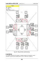
Page 197: ...node 1 transponder module per channel per LDx00 node per link Figure 96 Point to Point with Fiber only Redundancy Ring with Fiber only Redundancy No redundancy for TE I Os Primed and unprimed elements...

Page 198: ...er 2004 Figure 97 Ring with Fiber only Redundancy Installation The installation described in the Chapter 3 Installation applies for all redundancy network topologies In performing the installation ste...

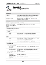
Page 199: ...8 and 9 10 TM2 SFP Transponders 1 Jumper JP2 is set in the TRANS RED position as shown in Table 11 on page 106 As noted there Transponders 1 and 2 of the TM2 SFP transponder module will operate in mut...

Page 200: ...ver time 25 ms WDM Wavelength Grid CWDM LD400 4 channels from 1310 to 1610 nm with 20 nm spacing LD800 8 channels from 1310 to 1610 nm with 20 nm spacing DWDM LD400 4 channels from 1529 55 to 1560 61...

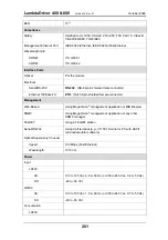
Page 201: ...ase TX ETH RJ45 8 pin shielded female connector Management Web Based Using MegaVision management application or MIB Browser SNMP Using MegaVision management application or any other SNMP manager TELNE...

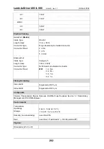
Page 202: ...ctor Pinout Category 5 100 m 330 ft RJ45 male 8 pin shielded connector MDI 1 Rx 2 Rx 3 Tx 6 Tx Fiberoptic Cabling Inter LDx00 Singlemode 9 125 m Intra LDx00 Singlemode 9 125 m Components Chassis Trans...

Page 203: ...r 2U33 x 324 mm 3 19 x 3 5 or 2U x 12 8 in 3 443 x 89 or 2U x 324 mm 3 17 5 x 3 5 or 2U x 12 8 in 3 482 x 200 or 4 5U x 267 mm 3 19 x 7 8 or 4 5U x 10 5 in 3 446 x 200 or 4 5U x 267 mm 3 17 5 x 7 8 or...

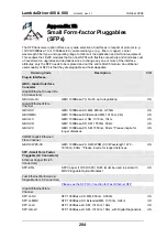
Page 204: ...onnectors GBIC GA RJ GBIC 1000Base TX RJ 45 auto negotiating US Gigabit Ethernet Fibre Channel GBIC SX GBIC 1000Base SX MM 850nm 0 550m US GBIC MMX GBIC 1000Base SX Extended MM 1310nm 2km US GBIC LX G...

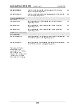
Page 205: ...Rate 1 2 1 Gbps SX MM 850nm 0 550m with Digital Diagnostics US SFP DGD LX SFP Dual Rate 1 2 1 Gbps LX SM 1310nm 2km with Digital Diagnostics US OC 3 LC Connectors SFP O3D LR1 SFP Fast Ethernet XD or O...

Page 206: ...R1 SFP Multi rate IR1 100 2700Mbps SM 1550nm 15km with Digital Diagnostics US SFP MR27D IR2 SFP Multi rate IR2 100 2700Mbps SM 1550nm 50km with Digital Diagnostics US CWDM Protocol Independent LC Conn...

Page 207: ...e by cutting off laser power on the access side whenever no power is received from the WDM side and vice versa Specifically power at the transponder WDM TX port is cut off when no power is received at...

Reviews: