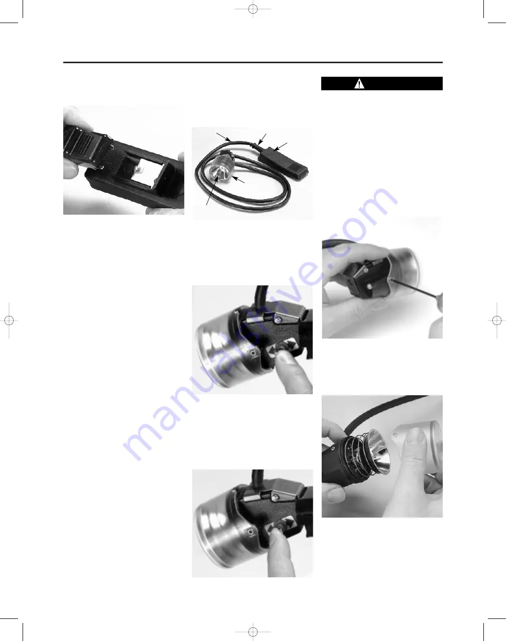
2. Slide the remote power device’s
connector onto the connector on
top of the battery until it stops.
3. At end of shift, or when finished
using the external device, remove
the external connection from the
battery top and reinstall the cover.
Place the battery on charge as
described in the Routine Battery
Maintenance section.
4. Refer to Illustrated Parts List for
replacement components.
ULTRALIGHT CAP LAMP SYSTEM
The Ultralight headpiece is made up of
the lamp-housing, which contains the
following parts:
— Bezel (cover);
— O-ring
— Main bulb and reflector assembly
— Spring
— secondary bulb
— 3-position switch
— Printed circuit board
— Charging key system
Bulbs are tungsten-halogen type con-
struction.
The main bulb is mounted in the
reflector, positioned for a tightly-
focused beam at maximum light out-
put, and then bulb and reflector are
cemented together. The main bulb
and reflector are held in the lamp-
housing by the bulb pins, which plug
into a flexible circuit board.
The secondary bulb gives enough light
for the wearer to leave the mine if the
bulb burns out. This bulb also plugs into
the lamp-housing circuit board, but
passes through the reflector. Since the
bulb is not centered in the reflector, it
does not give a bright, sharp spot.
The spring keeps the reflector tight
against the cover bezel. An O-ring,
mounted in a groove in the lamp-
housing, seals against the bezel to
help keep out dirt and moisture. A
stainless steel clip holds the head-
piece firmly to the miner’s cap. A
durable, abrasion-resistant cable con-
nects the headpiece to the battery and
allows freedom of movement.
Using the Ultralight Cap Lamp
System
The on-off switch is a 3-position switch,
located on the headpiece. The center
position is OFF. To operate the lamp:
1. Place the switch forward all the
way to light the primary bulb.
This bulb forms a tight spot for
maximum lighting.
2. Push the switch to the center posi-
tion to the lamp off.
3. Push the switch back all the way to
light the secondary bulb.
This bulb will not form a tight spot,
but will give enough light to leave
the mine.
If the main bulb fails to light, turn
the secondary light on, and immedi-
ately go to a well-lit area and
replace the main bulb.
MAINTENANCE OF THE
ULTRALIGHT CAP LAMP SYSTEM
HEADPIECE ASSEMBLY
Removing the Bezel (cover)
P/N 476705
1. Use a 3/32” allen wrench to thread
the two allen set screws
(P/N 634639) into the lamp-hous-
ing (P/N 486610).
Note
It is easier to remove the bezel by thread-
ing the set screws into the lamp-housing
rather than out of the lamp-housing.
2. Pull the bezel off the lamp-housing.
TAL 998 (L) Rev. 2 - 817184
5
Ultralight Cap Lamp System
Bezel
Reflector
Cable Protector
Battery
Cover
Battery
Cable
CAUTION
817184 8/13/99 9:42 AM Page 5


