background image

DF-8500 C Point type combustible gas detector with measuring range of 0~100%LEL


1.3 Safety and Precautionary Measures to be Adopted


Attention !


The  following  safety  instructions  must  be  observed  implicitly.  Only  in 
this way can the safety and health of the individual operators, and the 
correct functioning of the instrument, be guaranteed.


-  The device described in this manual must be installed, operated, and maintained in 

strict accordance with their labels, cautions, instructions, and within the limitations 
stated.


-  The device is designed to detect combustible gases in air.


-  Protect the device from extreme vibration. Do not mount the sensor in direct sunlight 

as this may cause overheating of the sensor.


-  The  device  must  be installed  with  the  sensor  inlet  pointing  downwards  to avoid 

clogging of the gas inlet by particles or liquids.


-  The only absolute method  to ensure  proper overall operation  of the device  is to 

check  it with  a known concentration  of the gas for  which  it has been calibrated. 
Consequently, calibration checks must be included as part of the routine inspection of 
the system.


-  As  with  all  devices  of  these  types,  high  levels  of,  or  long  exposure  to,  certain 

compounds in the tested atmosphere could contaminate the sensor. In atmospheres 
where the device may be exposed to such materials, calibration must be performed 
frequently to ensure  that the operation is dependable and display indications  are 
accurate.


-  The device must  not be  painted.  If painting  is done in an area where  a device  is 

located, care must be exercised to ensure that paint is not deposited on the sintered 
metal flashback arrestor in the gas sensor inlet, if so equipped. Such paint deposits 
would interfere with the gas diffusion process.


-  Use  only  genuine  MSA  replacement  parts  when  performing  any  maintenance 

procedures provided in this manual. Failure to do so may seriously impair instrument 
performance.  Repair  or  alteration  of  the  device,  beyond  the  scope  of  these 
maintenance  instructions  or  by  anyone  other  than  an  authorised  MSA  service 
personnel, could cause the product to fail to perform as designed.


-  The device  is designed  for applications  in  hazardous  areas under  atmospheric 

conditions.


-  For  correct  measurements,  the  combustible  gas  sensors  require  an  oxygen 

concentration greater than 10 %V/V. Oxygen enriched atmospheres, greater than 21


%V/V, can affect the measurement and the electrical safety of the device.


-  The response time of the device will be increased by the significant dust deposits on 

the sensor. Inspections for dust deposits must be done at regular intervals.


- Catalytic combustible gas sensors may produce low or zero response to 

combustible  gas  after  exposure  to  substances  such  as  Silicon,  Silane, 
Silicate,  Halide  and  compounds  containing  Fluorine,  Chlorine,  Iodine  or 
Bromine.


33


Summary of Contents for DF-8500 C

Page 1: ...MSA CHINA SAFETY EQUIPMENT CO LTD DF 8500 C 0 100 LEL Point type combustible gas detector with measuring range of 0 100 LEL User Manual P N 10203353 Rev 1 Date 2019 03 21...

Page 2: ...0C 0 100 LEL 1 1 1 1 2 4 4 4 5 6 6 6 7 8 8 10 13 13 14 21 21 22 22 23 23 24 24 25 25 25 26 26 27 28 28 29 1 3 1 4 2 2 1 2 2 3 3 1 3 2 4 4 1 4 2 4 3 4 4 5 5 1 6 6 1 6 2 6 3 7 7 1 8 9 9 1 9 2 9 3 9 4 10...

Page 3: ...DF 8500C 0 100 LEL 1 1 1 DF 8500 C SUPREMA Gasgard XL 9010 9020 8020 1 2 4...

Page 4: ...DF 8500C 0 100 LEL 1 3 10 V V 21 V V 5...

Page 5: ...DF 8500C 0 100 LEL 1 4 1 2 12 2 2 1 1 DF 8500 C 6...

Page 6: ...DF 8500C 0 100 LEL 2 2 15 LED 10 11 2 1 3 4 7 6 9 5 8 12 2 DF 8500 C 1 2 4 15 LED 3 LED 4 LED 5 6 LED 7 LED 8 9 10 11 12 7...

Page 7: ...DF 8500C 0 100 LEL 3 3 1 3 1 1 mm 3 DF 8500 C 8...

Page 8: ...0 100 LEL 3 1 2 DF 8500 C Nut M6 Washer 6 Mounting plate Washer 6 Bolt M6 12 Clamp 2 DF 8500 Pipe 2 DF 8500 C DF 8500 Nut M6 Washer 6 Mounting plate Washer 6 Bolt M6 12 Clamp 2 Pipe 2 DF 8500 C 4 DF...

Page 9: ...A 24V 24V 4 20mA 24V 24V 4 20mA 24V 24V P2 P1 P3 Alarm Device Red NC COM NO H ALARM L ALARM Black FAULTRELAY NO NC JP2 JP3 1 2 1 2 COM COM 2 3 2 3 P4 NC NO 5V TXD P6 RXD Material in the dashed GND lin...

Page 10: ...4V 24V DC 24V 4 20MA 4 20 mA NO COM NC P2 P1 P3 AF5000 NC COM NO H ALARM L ALARM FAULTRELAY NO NC COM COM P4 NC NO 5V TXD P6 RXD AF5000 Material in the dashed DF 8500 line rectangle is GND optional Re...

Page 11: ...DF 8500C 0 100 LEL 6 DF 8500 C 7 DF 8500 C DC24V DC24V 4 20 mA 8 DF 8500 C 1 2 3 4 5 3 6 7 12 1 2 3 1 2 3 1 DC 24V 2 DC 24V 3 4 20 mA 1 2 3...

Page 12: ...DF 8500C 0 100 LEL 4 4 1 4 0mA LED LED COMB 100 100 LEL 25 50 25 LEL 50 LEL 13...

Page 13: ...DF 8500C 0 100 LEL 4 2 4 2 1 1 2 4 3 IR Control 9 4 2 2 2 DF 8500 C 14 M 00 M 01 M 02 M 03 M 04 M 05 M 06 LED M 07 M 09 M 10 M 11 M 13 M 14 1 ON 2 OFF 3 4...

Page 14: ...DF 8500C 0 100 LEL M 00 LOC LOC 1 M 00 2 ON 3 4 4 4 M 01 1 M 01 2 ON 30 3 4 ON 5 0 6 OK 7 M 02 1 M 02 2 ON 30 3 4 ON 5 6 OK 7 8 15...

Page 15: ...8500C 0 100 LEL M 03 1 M 03 2 ON TEST GAS SENSOR USED DAYS GAS M 04 1 M 04 2 ON 3 4 4 4 TEST GAS CURRENT OFFSET 5 ON 6 7 OFF M 04 16 TEST GAS SENSOR USED DAYS GAS RANGE VER Z CALI COUNTER S CALI COUNT...

Page 16: ...06 LED LED 1 M 06 2 ON OFF 3 LED 4 OFF M 06 17 TEST GAS 50 5 99 CURRENT OFFSET 4 20 mA 120 90 150 4 20mA ALARM_L 25 5 1 ALARM_H 50 1 1 ZERO TIME 30 10 99 SPAN TIME 30 10 900 IDLE TIME 15 10 99 4 20MA...

Page 17: ...1 M 07 2 ON 04 4mA 3 ON 04 4mA 4 5 OFF M 07 4 22mA M 09 1 M 09 2 ON TEMP CURRENT S M 10 1 M 10 2 ON 3 4 4 4 L_ALARM DIR H_ALARM DIR ALARM RELAY 5 ON 18 TEMP CURRENT 4 20 mA S 1 3V S 1 3V VCC 24V VDD 5...

Page 18: ...6 ON OFF 7 OFF M 10 1 2 M 11 1 M 11 2 ON 3 4 4 4 M 11 OFF ON OFF M 11 19 L_ALARM DIR UP UP DOWN UP Down H_ALARM DIR UP UP DOWN ALARM RELAY DISE DISE ENER DISE ENER ALARM RELAY UNLK UNLK LOCK UNLK LOCK...

Page 19: ...DF 8500C 0 100 LEL M 13 M 01 M 01 M 13 1 2 M 13 3 ON 4 4 4 5 M 13 0 OFF M 13 ON 0 M 14 M 02 M 02 M 14 1 M 03 2 M 14 3 ON 4 4 4 5 M 14 M 03 OFF M 14 ON M 03 6 20...

Page 20: ...DF 8500C 0 100 LEL 4 3 1 1 4 2 2 M 01 4 2 2 M 02 OFF 4 4 4 0000 1 2 ON 3 4 21...

Page 21: ...DF 8500C 0 100 LEL 5 5 1 M 05 22...

Page 22: ...DF 8500C 0 100 LEL 6 6 1 MSA 23 IP66 IP67 225 125 106 Ex d IIC T6 Gb Ex tD A21 IP66 IP67 T80 1 8 4 5 95 16 0 34 0 V 3W 40 70 4 20 mA 80 120 300 0 6 DC 30V 2A...

Page 23: ...500 600 900 1400 9020 AC 1400 2100 2500 600 900 1400 9020 SIL DC24V 1300 1950 3000 600 900 1400 9020 SIL DC24V 1300 1950 3000 600 900 1400 9020 SIL AC 1300 1950 3000 600 900 1400 9020 SIL AC 1300 1950...

Page 24: ...DF 8500C 0 100 LEL 7 DF 8500 C 7 1 8 DF 8500 C PCBA DF 8500 10145768 SP 25 DF 8500 C SIL 10202789 DF 8500 10147141 SP 10173071 10178738 DF 8500 SIL 10202754 3450154...

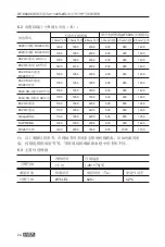
Page 25: ...DF 8500C 0 100 LEL 9 9 1 100 LEL LOC 110 26 LED 4 20 mA 4mA 4mA E XX 2mA LOC 110 20 5mA BOOT 0mA 0 3 2mA...

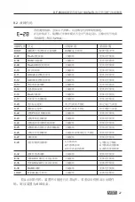
Page 26: ...EL 9 2 E 2mA 27 BOOT E 07 Flash E 08 RAM E 09 Flash CRC E 10 E 11 ADC24 E 12 ADC10 E 13 E 14 E 16 Flash E 17 E 20 E 21 E 22 PC E 23 E 24 E 25 E 26 E 27 E 28 1 2 3 1 2 3 E 32 E 34 ADC10 E 35 ADC24 E 36...

Page 27: ...3 4 4 10 9 4 EX d Suprema Gasgard XL 9020 9010 8020 PLC DCS 24V 1 24V DC GND 2 0V DC 4 20mA 3 4 20mA RLoad max 300 28 EX d 1 24V DC 24V Suprema Gasgard XL 9020 9010 8020 PLC DCS 2 0V DC GND 3 4 20mA...

Page 28: ...PTI Sensor PFD1oo1 PFD1oo1 SIL2 PFH1oo1 PFH1oo1 SIL2 PFD1oo2 PFD1oo2 SIL3 PFH1oo2 PFH1oo2 SIL3 16 Combustible Gas 2 86E 04 2 86 1 48E 07 14 8 1 44271E 05 1 44 7 49695E 09 7 5 52 Combustible Gas 7 35E...

Page 29: ...DF 8500C 0 100 LEL 72 4 20mA 4mA 20mA 5 LEL 20 52 0 5A EN60950 EN50178 SELV PELV SIL 3 1oo2 4 20 mA SJ T 11364 GB T 26572 GB T 26572 30 Pb Hg Cd Cr VI PBB PBDE DF 8500 C 0 100 LEL...

Page 30: ...quence Calibration Password Maintenance Sensor replacement Technical Data Major technical parameters of the detector Cable Lengths and Cross sections Meter Primary Performance Specifications Accessori...

Page 31: ...use Danger This product is supporting life and health Inappropriate use maintenance or servicing may affect the function of the device and thereby seriously compromise the user s life Before use the p...

Page 32: ...terials calibration must be performed frequently to ensure that the operation is dependable and display indications are accurate The device must not be painted If painting is done in an area where a d...

Page 33: ...n the events 1 Calibration debugging maintenance etc are performed by persons other than personnel from MSA or authorized by MSA 2 The product isinappropriately placed utilized or modified Without exp...

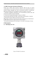
Page 34: ...evice has A gas sensor A four digit 15 segment LED display four LEDs for displaying the current status of the transmitter 10 11 2 1 3 4 7 6 9 8 5 12 Figure 2 Description of the Various Part of DF 8500...

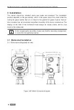
Page 35: ...ases lighter than air or closer to the ground for gases heavier than air Also consider how air movement may affect the ability of the device to detect as The display on the front of the instrument mus...

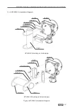
Page 36: ...500 C Installation Diagram Nut M6 Washer 6 Mounting plate Washer 6 Bolt M6 12 Clamp 2 DF 8500 Pipe 2 DF 8500 C Mounting on Verticalpipe DF 8500 Nut M6 Washer 6 Mounting plate Washer 6 Bolt M6 12 Clamp...

Page 37: ...the requirement of maximum cable lengths and cross sections see chapter 6 2 Water or impurities can penetrate the instrument through the cable In hazardous areas it is recommended to install the cable...

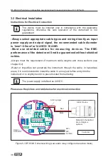
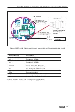
Page 38: ...4V Connect to DC 24V 4 20MA 4 20 mA output of device NO Not energized normally open COM Common terminal NC Not energized normally closed Passive Jumper P2 P1 P3 the black wire of AF5000 connect to COM...

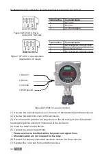
Page 39: ...nd to grab the two projections on the left and right side of the plastic housing and pull the electronic module out of the enclosure 4 Insert the cable into the device 5 Connect the wire to the termin...

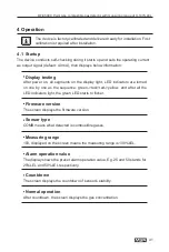
Page 40: ...ay light LED indicators are turned on one by one as the sequence green red red yellow and after all the LED indicators light the green LED starts to flicker Firmware version The screen displays the fi...

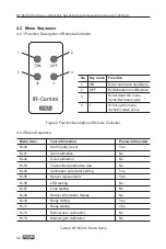
Page 41: ...elay reset Yes M 01 Zero calibration No M 02 Gain calibration No M 03 Transmitter parameters view No M 04 Calibration parameter setting Yes M 05 Sensor replacement Yes M 06 LED testing No M 07 Loop te...

Page 42: ...y accidents M 01 Zero calibration 1 Press to select the menu item M 01 2 The display displays zero countdown time after pressing ON with a default value of 30 seconds 3 Apply zero gas Pure Nitrogen or...

Page 43: ...for entering password 3 Enter the password see Section 4 4 4 If the password is correct you will enter the next submenu and be able to set multiple numerous parameters When you enter the next submenu...

Page 44: ...sor service time in days and return to the concentration measurement screen 5 Press OFF to return to the previous menu M 05 45 Submenu Parameter Meaning Default Adjustable Range Remarks TEST GAS Calib...

Page 45: ...loop is 4 mA 4 Press or to change data At this time both the flicker value and the output current will also change 5 Press OFF to exit the loop testing status and return to upper menu M 07 M 09 Senso...

Page 46: ...The energized de energized and self locking non self locking settings of high and low alarm relays cannot be setseparately 2 The alarm delay is only effective for low alarm relays In addition in the...

Page 47: ...le gas flow is caused by strong wind or other factors at the site 1 Press select the menu item M 13 2 Press ON and the screen will display the menu for entering password 3 Enter the password see Secti...

Page 48: ...tion cap regulated by MSA Failure to perform calibration for a long time or use of incorrect calibration flow and calibration cap may have adverse effects on the product performance The device is cali...

Page 49: ...ess ON to enter the next bit thousands hundreds tens units 3 After all of 4 digits has been entered the password becomes effective 5 Maintenance 5 1 Sensor replacement Danger Remove and reinstall the...

Page 50: ...Approximately 225 125 106 Explosion proof sign Ex d IIC T6 Gb Ex tD A21 IP66 IP67 T80 Weight Aluminum Appr 1 8 kgs SST Appr 4 kgs not including packing Humidity 5 to 95 RH non condensation Power sourc...

Page 51: ...l alarm AF5000 active mode 1 0mm cable 1 5mm cable 2 5mm cable 1 0mm cable 1 5mm cable 2 5mm cable 9020 dual channels powered by DC24V 1200 1800 2500 600 900 1400 9020 single channel powered by DC24V...

Page 52: ...nical Sensors 9 Appendix 9 1 Output Status If the DF 8500 C gas detector is exposed to a high gas concentration environment over 100 LEL the relay of the device will enter the locking state and it wil...

Page 53: ...erence check fault Mainboard fault Replace the electronic module E 20 Zero calibration timeout Mainboard fault Replace the electronic module E 21 Span calibration timeout Unstable zero gas flow Stabil...

Page 54: ...are pressed for over 10 minutes the menu will automatically return to the concentration measurement mode from any other screen 9 4 Wiring diagram Faulty Low alarm High alarm relay relay relay EX d Su...

Page 55: ...DF 8500 Gas Monitor 56 PTI Sensor PFD1oo1 PFD1oo1 SIL2 PFH1oo1 PFH1oo1 SIL2 PFD1oo2 PFD1oo2 SIL3 PFH1oo2 PFH1oo2 SIL3 16 weeks Combustible Gas 2 86E 04 2 86 1 48E 07 14 8 1 44271E 05 1 44 7 49695E 09...

Page 56: ...20 mA Afunctional check calibration check has to be done for the complete system A visual check has to be done together with the calibration A system check has to be done every year Calibration and a...

Page 57: ...20 mA output of the device must be monitored regarding deviations O Indicates that said hazardous substance contained in all of the homogeneous materials for this part is below the limit requirement...

Page 58: ...0 888 Product technology is continuously improved andcurrentdataisfor reference only P N 10203353 Rev 1 MSA China Safety Equipment Co Ltd Tel 0512 62898880 Fax 0512 62952853 ChinaHeadquarterofMarketin...

Reviews: