Contains electrical parts which have not been evaluat-
ed as an ignition source in flammable or explosive
atmospheres by MSHA/NIOSH.
Never substitute, modify, add, or omit parts. Use only
exact replacement parts in the configuration as speci-
fied by the manufacturer. Failure to follow this warning
can result in serious personal injury or death.
Note:
See NIOSH Approval Label, Inserted in the Users
Instructions for complete list of CAUTIONS and LIMITA-
TIONS for the Respirator.
•
Misuse or abuse of the NightFighter Heads-Up
Display System, the ICM Tx Unit, or the equipment
to which they are attached, or using this equip-
ment in a manner or situation not intended by the
manufacturers, may result in damage to the equip-
ment or may result in personal injury or death to
user or persons dependent on the user.
•
Always inspect the NightFighter Heads-Up Display
System and ICM Tx Unit for damage before use. If
damage is found, immediately remove the device
from service.
•
When NightFighter Heads-Up Display System is
used as a gauge (Not in conjunction with standard
pneumatic gauge) continuous operation mode
must be used to maintain NIOSH approval.
•
DO NOT alter these components. Altering will void
the Intrinsic-Safety rating and may affect the
Intrinsic-Safety of the device.
Note:
The NightFighter Heads-Up Display System
Receiver is for use with an Ultra Elite
®
Facepiece only. It
cannot be used without the proper installation of the
Receiver, Facepiece Bracket and either NightFighter
Heads-Up Display System Transmitter or ICM Tx Unit
from MSA.
1. The NightFighter Heads-Up Display System allows a
user to clearly and easily see air cylinder content while
wearing an SCBA equipped with the Ultra Elite
Facepiece.
Note:
The NightFighter Heads-Up Display can only be
used with an Ultra Elite Facepiece.
2. The NightFighter Heads-Up Display consists of three
(3) separate assemblies:
• Bracket assembly attached to an Ultra Elite
Facepiece.
• Receiver mounted on the bracket assembly.
• ICM Tx Unit or Transmitter assembled to the gauge
line. (See Installation Instruction P/N 10035581,
transmitter only).
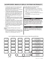
3. The NightFighter Heads-Up Display System Receiver
shows the user the air cylinder content in one quarter
cylinder increments, from a full cylinder to an empty
cylinder, by an LED light pattern.
4. The NightFighter Heads-Up Display System
Transmitter is assembled to the gauge line hose. (The
ICM Tx Unit serves as the transmitter).
The transmit-
ter sends a signal to the receiver (on the facepiece) of
the air cylinder content.
5. The NightFighter Heads-Up Display System Receiver
has seven (7) LEDs that are used to form light pat-
terns.
6. The NightFighter Heads-Up Display System Receiver
has a photo sensor for the LED lights to automatically
adjust the brightness of the LED based on to the
brightness as measured outside of the facepiece.
7. The NightFighter Heads-Up Display System Receiver
will indicate a low battery by a Yellow LED light for the
receiver, ICM Tx Unit, or NightFighter Heads-Up
Display System Transmitter.
The NightFighter Heads-Up Display System operates
using (4) standard AA alkaline batteries in the ICM Tx and
(2) standard AA alkaline batteries in the receiver. When
using a Nightfighter Heads-Up Display System with stan-
dard Transmitter (2) AAA alkaline batteries are needed.
The NightFighter Heads-Up Display System notifies the
user when the batteries need to be replaced.
TABLE OF CONTENTS
Description ..............................................................................................................................................................................2
System Operations..................................................................................................................................................................5
Using the ICM Tx Unit.............................................................................................................................................................9
During Use.............................................................................................................................................................................13
Cleaning and Maintenance ...................................................................................................................................................15
Quick-Fill
®
System Operation................................................................................................................................................17
URC Assembly Operation .....................................................................................................................................................21
Warranty ................................................................................................................................................................................24
DESCRIPTION
2
TAL 709 (L) Rev. 4 - 10058881

