9
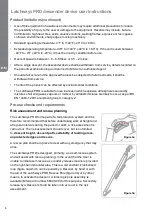
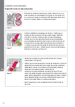
• Ensure that the release cord guide is undamaged (Figure 8).
• Inspect the descent line, load-line and release cord for signs of cuts,
abrasion, fraying, tears, mould, discolouration, chemical attack or
excessive build-up of dirt. Check the stitching for signs of loosening,
pulling or cut thread. Excessive build-up of dirt may prevent the
descent line from pulling through the device. If damage is apparent
the Latchways PRD descender device shall be removed from
service and advise sought from MSA or authorised agent.
• After inspection close the zip on the backpack fully.
Figure 8
Figure 9
• Unzip the back panel of the backpack and inspect the Attachment
locking bolt for signs of damage, distortion, corrosion or cracking.
Ensure that the bolt is secure (Figure 9). If damage is apparent or
the bolt insecure the Latchways PRD descender device shall be
removed from service and advise sought from MSA or authorised
agent.
• Inspect all system components and subsystems according to MSA’
instructions.
Harness
• The Latchways PRD descender device shall only be used with an Approved harness.
• Approved harnesses shall comply with relevant standards within the country of use.
ANSI
ANSI Z359 11 2014
CSA
CSA Z259 10-12 (2013)
• Approved harnesses shall be examined and maintained in accordance with the manufacturers'
instructions.
• An Approved harness is designed to arrest a single fall from height only once. If subjected to an
arrested fall the Approved harness shall be withdrawn from service and destroyed.
Using the Latchways PRD descender device
Fitting and adjusting the harness
The safety of the User is dependant upon a correctly fitted Approved harness. This shall be worn over
any clothing. Refer to separate Approved harness manufacturers' User instructions for fitting, inspection
and maintenance of the Approved harness
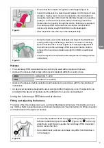
• Connect the karabiner of the energy absorbing lanyard to the rear
fall arrest attachment point marked
A
1
(Figure 10).
A
1
is the only
attachment point that will operate the Latchways PRD descender
device rescue function.
• Note: Attachment point size and shape may differ from that shown
in the diagram.
Figure 10
A
1
EN


