7
Version 0.1
Operating Manual
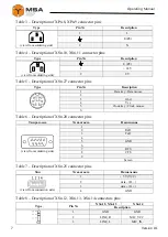
Table 3 – Description of XPn.8, XPn.9 connector pins
Type
Pin №
Description
1
2
(view from soldering side)
1
L
E (PE)
2
N
Table 4 – Description of XSn.10, XSn.11 connector pins
Type
Pin №
Description
1
2
(view from soldering side)
E (PE)
1
+ 24 V
2
0 V
Table 5 – Description of ХSn.27 connector pins
Type
Pin №
Description
1
Data key / Data mouse
2
‒
3
Gnd
4
Vcc
5
Clock key / Clock mouse
6
‒
Table 6 – Description of XSn.20 connector pins
Тип разъема
№ контакта
Назначение
5 4 3 2 1
9 8 7 6
(view from soldering side)
1
‒
2
RxD
3
TxD
4
‒
5
GND
6
‒
7
RTS
8
CTS
9
‒
‒
Screen
Table 7 – Description of XSn.25 connector pins
Тип
№ контакта
Назначение
(view from connection side)
1
+ 5 V (VCC)
2
data – (D –)
3
data + (D +)
4
GND
Table 8 – Description of XSn.12, XSn.13, XSn.14 connectors pins
Type
Pin №
XSn.12, XSn.13
XSn.14
Description
1
GND
GND
2
LINE_R
MIC_VCC
3
LINE_L
MIC_IN
Summary of Contents for MPC-127
Page 2: ......


