SUPREMATouch
56
Operation of the System
MSA
US
Maintain Menu
Access to the fields in the “Maintain” menu is restricted. Data can displayed, but changes and de-
letions are only possible after entering the maintenance password [or higher] or operating a key
switch.
Calibration Submenu
To calibrate the individual gas detection inputs a manual 2-point calibration procedure can be
used and if required an automatic presetting can be done during the first calibration. After a cali-
bration process has been started using the MDO, ‘Zero’ gas must be applied to the sensing head.
Then a ‘Test’ [span] gas must be applied. The results of a calibration are then displayed and saved
[see section 7.1 Maintenance and Adjustment].
NOTE: The presetting is applied immediately and cannot be cancelled or discarded.
Calibration parameters for the individual inputs can be set in the calibration menu. From that point
on the calibration is controlled by the SUPREMATouch.
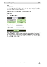
The window is divided into two subwindows:
-
“Start calibration”
-
“End calibration”
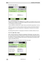
If an input is selected that is not already in calibration mode, the “Start calibration” window ap-
pears. If an input is selected that is already in calibration mode, the “End calibration” window ap-
pears.
The functions of the individual fields are described below.
The “Meas. Point” and “Tag” fields are contained in both subwindows.
Meas. Point
Field type: Selection
The field contains a list of all configured inputs. After an input number is selected, the rest of the
fields are filled, depending on whether or not the input is in calibration mode.
Global parameter changes and actions using the fields described below apply to the in-
put selected in this field.
Summary of Contents for SUPREMA Touch
Page 2: ...Manual SUPREMATouch Fire and Gas Warning Unit Order No 10126972 00...
Page 7: ...SUPREMATouch 6 Contents MSA US...
Page 8: ...User Instruction Manual SUPREMATouch Fire and Gas Warning Unit...
Page 104: ...Service and Maintenance Guide SUPREMATouch Fire and Gas Warning Unit...
Page 112: ...Installation and Start Up Manual SUPREMATouch Fire and Gas Warning Unit...
Page 151: ...SUPREMATouch 150 Installation MSA US Fig 79 MCP Module standard configuration...
Page 303: ...SUPREMA 302 Dimensions MSA GB 16 Dimensions 16 1 Rack...
Page 306: ...MSA AUER MSA Dimensions SUPREMA 305 GB MRO20 8 TS Module 1 3 2 69 90...
Page 307: ...SUPREMA 306 Dimensions MSA GB MRO20 16 TS Module 2 5 2 64 73 relay dependent 90...
Page 308: ...MSA AUER MSA Dimensions SUPREMA 307 GB MRC TS Module MGT 40 TS Module...
Page 309: ...SUPREMA 308 Dimensions MSA GB MHD TS Module MAT TS Module...


