background image

ULTRA ELITE RESPONDER FACEPIECE

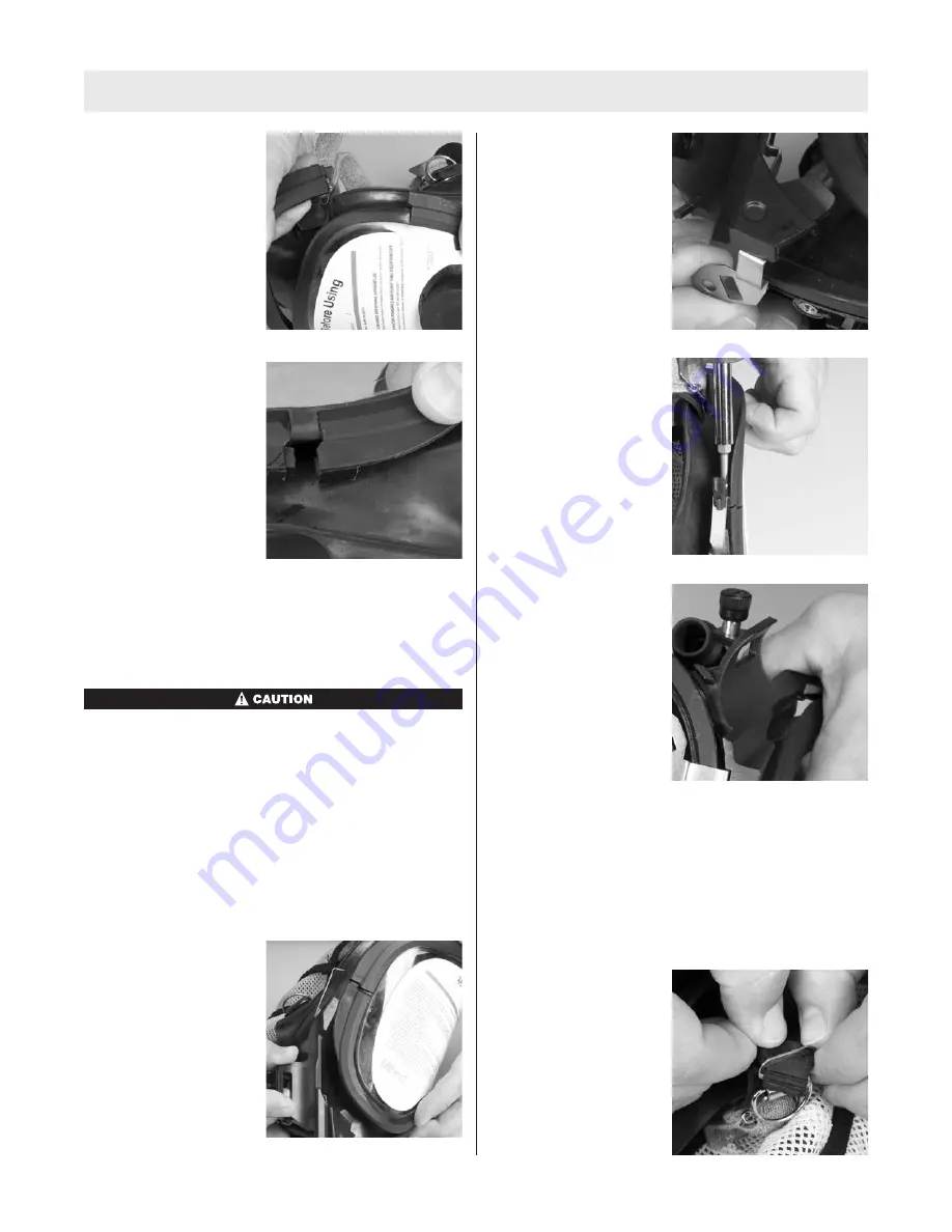
8. Install the lens ring.

9. Press the ring halves

together to mate the
ends.

10. Install a screw on each side.

a. If the screws do not go in easily, pull them out and

try again. Avoid cross threading.

11. Alternate tightening the left and right screws to seat

the ring evenly.

Do not over tighten. Facepiece rubber must not be

visible through the joint. If the facepiece rubber is

visible, reassemble.

Installing the M7 HUD Mounting Bracket

M7 HUD Mounting Bracket

P/N 10083133

Note:

Remove the component housing cover before

installing the M7 HUD Mounting Bracket (See

Removing

the Component Housing

for instructions). If necessary,

remove the lens ring screws (See

Removing the Lens

Ring and Lens Assembly

for instructions).

1. Slide the bracket

assembly onto the
facepiece.

a. Make sure that tab

is under the lower
lens ring.

2. Reinstall the lens ring

screw.

3. Align the screw hole in

the lower metal tab
with component
housing screw hole.

4. Reinstall the component housing cover. (See

Installing the

Component Housing Cover

for

instructions.)

5. Check alignment and tighten screws.

Installing the SpeeD-ON Head Harness

SpeeD-ON Head Harness

P/N 10031102

1. Install the crown buckle.

a. Insert the long tab of

the lug into the
D-ring.

16

TAL 012 (L) Rev. 1 - 10096395

Summary of Contents for Ultra Elite Responder

Page 1: ...TAL 012 L Rev 1 MSA 2010 Prnt Spec 10000005389 I Mat 10096395 Doc 10096395 Ultra Elite Responder Facepiece MAINTENANCE AND REPAIR...

Page 2: ...10093933 Lens Assembly 3 10025295 Lens Receptacle Inhalation Valve Disc 4 10082477 O Ring 5 10093919 Lens Port Plug 8 804805 Lower Lens Ring 6 804804 Upper Lens Ring 7 10093945 Screw 9 10083233 HUD B...

Page 3: ...L Rev 1 10096395 ULTRA ELITE RESPONDER FACEPIECE 1 2 6 7 8 9 10 12 11 13 14 17a 18 19 20 21 22 23 24 25 27 28 29 30 31 32 33 34 7 16 15 32 35 37 36 3 5 38 39 26 4 17 15a Christo Lube Christo Lube Expl...

Page 4: ...Cover for instructions 4 TAL 012 L Rev 1 10096395 Table of Contents Disassembly 4 SpeeD ON Head Harness 4 M7 HUD Mounting Bracket 4 Lens Ring and Lens Assembly 5 Nosecup 5 Component Housing Cover Rem...

Page 5: ...bly P N 10093933 See Installing the Lens and Lens Ring for instructions 1 Use a Philips screwdriver to remove the screws from the lens rings 2 Remove the lens rings 3 Pull the lens out of the groove R...

Page 6: ...the Exhalation Valve 1 Turn the facepiece so that the exhalation valve is down and allow the valve to fall into your hand Removing the Component Housing 1 Remove the component housing cover See Removi...

Page 7: ...e piston f Use the o ring removal tool to remove the o ring g Discard the o ring Removing the Pneumatic Assembly 1 Remove the pneumatic tube a Use retaining ring pliers to remove the retaining ring b...

Page 8: ...emoving the External and Internal Drinking Tubes 1 Pull the external drinking tube off of the connector 2 Pull the internal drinking tube out of the component housing 3 Pull drinking tube connector ou...

Page 9: ...tabbed spoke with the centerline Note Alignment of the tabbed spoke with the centerline provides a visual guide when installing the drinking tube assembly and is not critical to facepiece function Not...

Page 10: ...til it seats Installing the Speaking Diaphragm Speaking Diaphragm P N 804809 Retaining Ring P N 804808 1 With the gasket forward perforations facing the wearer place the diaphragm in the component hou...

Page 11: ...o Lube P N 604070 to a new o ring d Install the o ring e Install the pneumatic nut Use the inch pound torque wrench socket and Pneumatic Nut Special Tool P N 10086032 and tighten to 8 in lbs Note Spec...

Page 12: ...row end of the housing work the housing into the groove Note Ensure that the housing is captured completely by the groove and that the centerline marks are aligned 2 Insert the narrow end of the housi...

Page 13: ...ket and screw provided See Installing the ClearCommand Communication System Mounting Bracket for instructions Installing the Exhalation Valve Exhalation Valve P N 814459 1 If necessary assemble the ex...

Page 14: ...e c Stow the external drinking tube coupling Note To reduce snag hazards stow the tube under the flange Installing the Nosecup 1 Install the nosecup a Pass the drink tube through the x cut in he nosec...

Page 15: ...piece assembly is complete 3 Align the lens centerline marks top and bottom with the facepiece centerline marks Note Verify proper lens selection NFPA approved lenses bear the Identification Mark A at...

Page 16: ...cover before installing the M7 HUD Mounting Bracket See Removing the Component Housing for instructions If necessary remove the lens ring screws See Removing the Lens Ring and Lens Assembly for instru...

Page 17: ...604070 2 Install the o ring Lens Receptacle Inhalation Valve Removing the Lens Receptacle Inhalation Valve 1 Stretch the inhalation valve disc off the post Note Lens assembly removed for illustration...

Page 18: ...place the ClearCommand Communication System 1 Use a Phillips screwdriver to remove the lens ring screw 2 Use a Phillips screwdriver to remove the component housing ring screw 3 Remove the component ho...

Page 19: ...the retaining ring P N 10023505 and firmly hand tighten 5 Install the nosecup a Stretch the nose cup over the exhalation valve flange b Stretch the nose cup over the retaining ring 6 Route the microp...

Page 20: ...andards suggest user training in cleaning procedures Use MSA Confidence Plus Cleaning Solution P N 10009971 It cleans and disinfects in one operation retains germicidal effectiveness in hard water to...

Reviews: