background image


7                                                                                                                                                          Version 1.0 

Operating Manual


1.4


M

EASUREMENT TOOLS

,

 INSTRUMENTS AND APPLIANCES


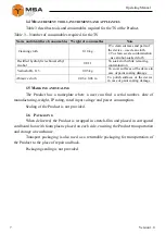
Table 3 describes tools and consumables required for the TS of the Product. 

Table 3 – Number of consumables required for the TS 


Name and identifier of consumables  Weight of consumables 

Note 

 Cleaning cloth 

0.10 kg 

1


To clean surfaces and parts of 

the device – use clean cloth 
2


 To clean severe contamination 

– use alcohol-soaked cloth 

Rectified hydrolytic technical ethyl 
alcohol  

0.01 l 

To soak cloth while removing 
contamination 

Varnish АК-113  

0.05 kg 

To cover surfaces of the device in 
case of paint coating damage  

Abrasive cloth  

0.06 х 0.06 m 

To  polish  surfaces  of  the  device 
in case of paint coating damage 

1.5


M

ARKING AND SEALING


The  Product  has  a  nameplate


where  a  user  can  find  a  serial  number,  date  of 

manufacturing, weight, IP rating, rated input voltage and power consumption.  

Sealing of the Product is not provided. 

1.6


P

ACKAGING


When delivered, the Product is wrapped in stretch-film and placed in corrugated 

cardboard box with foam plastic placed on each side, ensuring the Product transportation 
and storage at warehouse.  

Transport packaging  is  also  used  as  a  returnable packaging  for  transportation  of 

the Product to the place of repair and back.  

Packaging sealing is not provided. 

Summary of Contents for UT-1200C

Page 1: ...Liability Company NPK MORSVYAZAVTOMATICA 26E Kibalchicha str 192174 St Petersburg Russia info unicont com www unicont com Phone 7 812 622 23 10 Fax 7 812 362 76 36 MARINE HEATERS UT S UT C Operating...

Page 2: ...ackaging 7 2 INTENDED USE 8 2 1 Operational constraints 8 2 2 Preparation for the Product operation 8 2 3 Usage of the Product 9 3 TECHNICAL SERVICE OF THE PRODUCT 13 3 1 General instructions 13 3 2 S...

Page 3: ...use technical service current repair as well as disposal information for its components Only those who have read operational documentation shall be permitted to operate the Product Only those who have...

Page 4: ...AC 50 Hz 127 114 3 to 139 7 220 198 to 242 380 2 phase 342 to 418 Power consumption W 300 600 800 1200 1800 Heating capacity m3 7 14 19 27 42 Dimensions see ANNEX A Weight kg 7 8 7 8 10 0 10 0 10 5 P...

Page 5: ...air temperature reaches the preset one 2 temperature fuse sensor relay F 1 which prevents the Product casing from overheating by disconnecting TEH power circuit 1 terminal block to connect power supp...

Page 6: ...rols and indication The following controls and LEDs are located on the Product casing knob of temperature controller TC 1 see 1 figures 3 4 to set required air heating temperature power piano type on...

Page 7: ...ver surfaces of the device in case of paint coating damage Abrasive cloth 0 06 0 06 m To polish surfaces of the device in case of paint coating damage 1 5 MARKING AND SEALING The Product has a namepla...

Page 8: ...mechanical damage Connect the Product to the power mains only considering input power requirements The Products must be switched off and grounded before connection The staff shall follow The technical...

Page 9: ...g protection and to ensure natural convection Install the Product vertically the panel with control elements shall be on the right hand side When mounting leave not less than 70 mm free space from the...

Page 10: ...see Figure 5 and unscrew four mounting brackets inside the casing on the rear side see Figure 6 Figure 5 Take off the front panel Figure 6 Unscrew mounting bracket 2 screw mounting brackets onto the v...

Page 11: ...Mount the casing on the vertical bulkhead and check that the mounting is reliable Figure 8 Hinge the casing onto the brackets Figure 9 Screw the casing onto the brackets 4 provide all necessary conne...

Page 12: ...cable with core section 2 5 4 0 mm2 2 2 3 Switching the Product on instructions While connecting the Product and preparing it for operation follow the steps below make sure that power mains voltage c...

Page 13: ...operation of the Product heat it up for 3 hours under the rated voltage in the beginning of use and at times during operation 3 2 SAFETY FEATURES While providing TS the staff shall follow instruction...

Page 14: ...eaning liquids or chemicals Do not press hard on the surface while cleaning Do not spray liquid directly to the surface of the Product 4 In case of varnish damage clean it with abrasive cloth then alc...

Page 15: ...n preserved condition in Manufacturer s packaging boxes The time of represervation 2 years from the Manufacturer s commissioning The represervation is done in heated rooms in the same order as the pre...

Page 16: ...epair is ON is STRICTLY PROHIBITED It is PROHIBITED to put a poster DO NOT switch on Under Operation when power supply switch is in OFF position Installation commissioning and repair works are PROHIBI...

Page 17: ...nditions 5 to 40 with the concentration of dust oil moisture and aggressive impurities in the air within the required limits for the working areas of production facilities After storage or transportat...

Page 18: ...tion in sealed and heated compartments sea transportation in dry service spaces The Product must be transported in compliance with transportation rules applicable for each means of transport During lo...

Page 19: ...o send an over age equipment unit to the manufacturer for its further disposal Proper disposal of Product components allows avoiding possible negative envi ronmental and health impacts and it also all...

Page 20: ...l not consider damage claims in case of violation of operating conditions More information about warranty terms you can find on the official site of NPK MSA LLC section Support Address and contacts of...

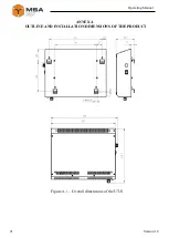
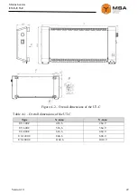
Page 21: ...21 Version 1 0 Operating Manual ANNEX OUTLINE AND INSTALLATION DIMENSIONS OF THE PRODUCT Figure 1 Overall dimensions of the UT S...

Page 22: ...ne heaters UT S UT C Figure 2 Overall dimensions of the UT C Table 1 Overall dimensions of the UT C Type X mm Y mm UT 300C 416 6 264 9 UT 600C 516 6 364 9 UT 800C 616 6 464 9 UT 1200C 846 6 694 9 UT 1...

Page 23: ...23 Version 1 0 Operating Manual FOR NOTES...

Reviews: