INSTALLATION INSTRUCTIONS
M S D I G N I T I O N
• w w w . m s d i g n i t i o n . c o m • ( 9 1 5 ) 8 5 7 - 5 2 0 0 • FA X ( 9 1 5 ) 8 5 7 - 3 3 4 4
sources. Make sure that the wiring reach their connections. Use the Control as a template to mark
the mounting holes. Remove the unit and drill the holes with a 1/8” drill bit. Use the supplied screws
to mount the unit.
Control Knob
Find a suitable location on the dashboard that can easily be reached by the driver. Drill a 7/16” hole,
install the supplied snap bushing and route the harness wires through. Make sure the harness reaches
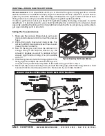
the connector on the BTM before mounting the control knob. Install the supplied 2-pin Weather-tight
connector (Figure 2) on the harness and connect it to the Grey/Black wire on the BTM. The order of
the wires inside the connector is not important.
Boost Line
Connect one end of an 1/8” ID vacuum line to the brass spigot on the BTM. Connect the other end of the
hose to a ported source such as the intake manifold or
below the throttle blades of the carburetor or throttle
body. If you already have a boost gauge you can tee
into that line.
AdjustIng the Boost
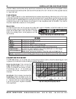
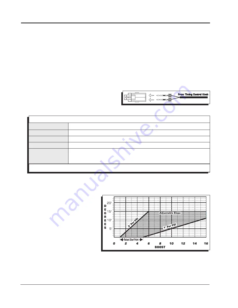
The PN 8962 allows you to set the amount of ignition retard as well as when the retard begins, both
in relation to the amount of boost being produced (Figure 3).
Dash Control Knob: This controls the
slope of the retard. That is, how much
timing is removed per pound of boost.
The settings are 0° – 3° of retard per
pound of boost with a maximum of 15°
of retard.
Start Point: This is where you adjust the
beginning of the boost retard curve. You
can adjust the start point of the slope from
0 – 5 pounds of boost. A typical setting is
2 psi for most users. Figure 3 illustrates
this adjustment.
Figure 2 Connecting the Control Knob Harness.
Red:
Black:
Yellow:
White:
Green/Violet
2-Pin Connector:
Connects to switched 12 volts.
Connects to Ground.
Connects to MSD Ignition’s White wire.
Connects to points or amplifier trigger wire on the engine.
Connects to the magnetic pickup of the distributor or crank trigger.
Green is negative, Violet is positive.
Note: When using this connector, the white wire loop must be cut.
Note: The White wire and 2-Pin Magnetic Pickup wires will never be used at the same time!
Figure 3 Setting the Timing Adjustments.
WIRIng


