4
INSTALLATION INSTRUCTIONS
M S D
• W W W . M S D P E R F O R M A N C E . C O M • ( 9 1 5 ) 8 5 7 - 5 2 0 0 • F A X ( 9 1 5 ) 8 5 7 - 3 3 4 4
temperature reading from an external temperature sensor. Also, the selected input wire can be used
to trigger a time counter, like a launch wire, and control the time of activation as well as the duration
of the output. The state of the inputs and outputs can be observed in the monitor window in real time.
POWER GRID MODE
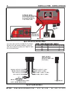
The Power module is connected to the Power Grid (PN7730) via the CAN connector.
In Power-Grid mode, the Power Module retains all the features available in Stand-Alone mode and
expands the control and programmable features. In addition to the four input wires, the user can
select the “launch wire” signal from the Power Grid as the activation source. Also, the output control
can be enabled/disabled based on the engine speed (RPM) reading from the Power Grid.
In addition to providing expanded control over the outputs, Power Grid Mode utilizes the Power Grid
data recorder.
Another feature the Power Grid adds to the Power Module is the ability to control ignition timing retard
as a function of “Time From Activation”. Time from activation is the time elapsed since the activation
of the selected Power Module input wire. A 2-D plot of “timing retard vs time from activation” is
provided for this feature.
Note:
For more information on the features and settings, please refer to the “SETTINGS” section below.
PROGRAMMABLE FEATURES
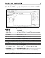
OUTPUT SETTINGS
These settings allows control over the behavior of each output. Each one of the four outputs has an
“OUTPUT SETTINGS” sub-tab and is configured independently.
SETTINGS
Features, such as the frequency, current limit and activation source, can be configured under this tab.
Frequency:
Signal frequency of the Solid state relay output in PWM mode only.
Current Limit:
When the solid state output current exceeds the set value, the output will turn OFF until
the next turn-on command.
Note:
Continuous load current over 20 Amps may overheat the
driver that consequently will turn OFF to protect itself.
Temperature Control:
Sets the method that the external temperature sensor controls the
corresponding output of the solid state relay.
Disable:
The temperature sensor signal does not affect the output.
ON/OFF:
The output will be ON when the sensor temperature is above the value in the
“Temperature Setting” or OFF when the sensor temperature is below it. If “AC Input” is used
, the AC is ON the output will be ON irrespective of the sensor temperature.
PWM:
The output will have a varying duty cycle between 50 and 100%, or 0% to control the
temperature until it reaches the desired value. A value of 0% is valid only if “AC Input is OFF
or not used. Otherwise, the minimum value is 50% duty cycle.
Temperature Setting:
The output state will change to maintain the value set here. For example
in “ON/OFF” mode the output will be ON when the measured sensor temperature is above
this setting and the output will turn OFF when the sensor temperature is below this setting.
Note: when the “AC Input” is ON, the output will be ON regardless of the temperature.
AC Input:
Selects the wire that will indicate AC ON. When the AC is ON the output will be at
least 50% ON in PWM mode or fully ON in ON/OFF mode. The “AC Input” setting is available
only in “Temperature Control” mode.
Wire Activation Source 1 - 4,:
Determines which of the inputs must activate for the output to be ON.
All non-disabled inputs except the Launch must be ON for the output to be ON. If the Launch
is selected, the Launch mode must be OFF for the output to be ON.
Note:
The inputs selected act as an AND function. Meaning: All the defined inputs must be ON at
the same time to enable the output wire
Timer During Wire Disable:
Determines the status of the Channel’s Timer while the output is


