2-5
Hardware Setup
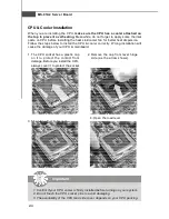
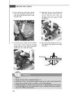
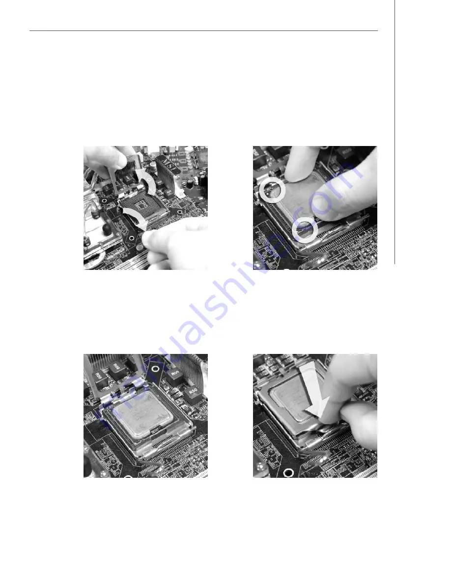
6. After confirming the CPU direction
for correct mating, put down the
CPU in the socket housing frame.
Be sure to grasp on the edge of
the CPU base. Note that the align-
ment keys are matched.
8. C over the load plate onto the
package.
5. Lift the load lever up and open the
load plate.
7. Vis ually ins pec t if the C PU is
seated well into the socket. If not,
take out the CPU with pure vertical
motion and reinstall.
alignment
key
PDF created with pdfFactory Pro trial version
www.pdffactory.com
Summary of Contents for 3200 Master Series
Page 1: ...i 3200 Network MS 91A2 V1 X Server Board...
Page 5: ...v WEEE Waste Electrical and Electronic Equipment Statement...
Page 6: ...vi...
Page 7: ...vii...
Page 12: ...MS 91A2 Server Board 1 4 3200 Network MS 91A2 V1 X Server Board Mainboard Layout...
Page 16: ......
Page 40: ......
Page 46: ...3 6 MS 91A2 Server Board Advanced CPU Configuration...
Page 55: ...3 15 BIOS Setup Boot Boot Settings Configuration...


