background image

3-11

BIOS  Setup

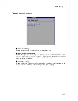
 Event Log  Configuration

  View  Event  Log

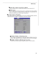
Press [Enter] to view the contents of the DMI event log.

 Mark All Events as  Read

d

Press [Enter] and a screen pops up, asking users to confirm whether or not to
clear all DMI event logs immediately. Press [Y] and [Enter], the BIOS will clear all
DMI event logs right away.

 Clear Event Log

W hen this setting is set to [Yes], the DMI event log will be cleared at next POST
stage. Then, the BIOS will automatically set this option to [No].

PDF created with pdfFactory Pro trial version 

www.pdffactory.com

Summary of Contents for 3200 Master Series

Page 1: ...i 3200 Network MS 91A2 V1 X Server Board...

Page 2: ...trademarks of Intel Corporation PS 2 and OS 2 are registered trademarks of International Business Machines Corporation Windows 98 2000 NT XP Vista are registered trademarks of Microsoft Corporation N...

Page 3: ...inserting any add on card or module 9 All cautions and warnings on the equipment should be noted 10 Never pour any liquid into the opening that could damage or cause electrical shock 11 If any of the...

Page 4: ...interference by one or more of the measures listed below Reorient or relocate the receiving antenna Increase the separation between the equipment and receiver Connect the equipment into an outlet on...

Page 5: ...v WEEE Waste Electrical and Electronic Equipment Statement...

Page 6: ...vi...

Page 7: ...vii...

Page 8: ...apter 1 Getting Started 1 1 Mainboard Specifications 1 2 Mainboard Layout 1 4 Watch Dog Timer Setting 1 5 Chapter 2 Hardware Setup 2 1 Quick Components Guide 2 2 CPU Central Processing Unit 2 3 Memory...

Page 9: ...ork accommodates the latest Intel Pentium 4 Quad Core Kentsfield Yorkfield Dual Core Conroe Wolfdale Celeron D processors in LGA775 package and sup ports up to two unbuffered non ECC DDR2 667 800 DIMM...

Page 10: ...el ICH9 chipset M emory 2 unbuffered non ECC DDR2 667 800 DIMM slots 240pin 1 8V Up to 8GB memory capacity LAN Supports 6 PCI E Gb LAN by Intel 82575 including 2 pair RJ45 LAN bypass and 1 pair fiber...

Page 11: ...k activity LEDs 5 individual RJ 45 Gigabit LAN ports with LEDs Onboard Connectors 1 USB 2 0 connector 2 ports 1 serial port connector 1 D Sub VGA connector 1 mouse keyboard connector 1 SPI Flash ROM c...

Page 12: ...MS 91A2 Server Board 1 4 3200 Network MS 91A2 V1 X Server Board Mainboard Layout...

Page 13: ...x al B Set pin 77 to WDTO function mov dx 04eh mov al 02Dh Register 2Dh out dx al inc dx in al dx and al 0FEh Config Bit 0 As 0 out dx al Config PIN 77 as WDTO C Select Logical Device 8 mov dx 04eh mo...

Page 14: ...MS 91A2 Server Board 1 6 mov dx 04eh CR 30h bit 0 fill in 1 mov al 030h out dx al inc dx mov al 01h out dx al Setup WDTO count mode Set bit 4 and bit 3 by request Set bit 2 to 0 Set bit 1 to 1...

Page 15: ...ng Started mov dx 04eh CR F7h bit 4 fill 0 clear event mov al 0f7h out dx al inc dx in al dx and al 0efh out dx al CR F6h bit0 7 fill in counter time E Exit configuration mode mov dx 04eh mov al 0aah...

Page 16: ......

Page 17: ...dures While doing the installation be careful in holding the components and follow the installation procedures For some components if you install in the wrong orientation the components will not work...

Page 18: ...N1 2 p 2 16 JUSB1 p 2 17 JSPI1 p 2 15 J3 p 2 19 J_BOOT1 p 2 21 CPU_FAN1 p 2 16 CPU p 2 3 DIMM Slots p 2 7 J_CMOS1 p 2 21 Front Panel I O p 2 9 JPWR1 p 2 8 JLCD1 p 2 18 JP1 p 2 19 JPWR2 p 2 8 JPBTN1 p...

Page 19: ...persion Yellow triangle is the Pin 1 indicator The pin pad side of LGA 775 CPU Yellow triangle is the Pin 1 indicator Alignment Key Alignment Key Important Overheating Overheating will seriously damag...

Page 20: ...it to protect the contact from damage Before you install the CPU always cover it to protect the socket pin 3 The pins of socket reveal CPU Cooler Installation When you are installing the CPU make sure...

Page 21: ...me Be sure to grasp on the edge of the CPU base Note that the align ment keys are matched 8 Cover the load plate onto the package 5 Lift the load lever up and open the load plate 7 Visually inspect if...

Page 22: ...retention tab Important 1 Read the CPU status in BIOS Chapter 3 2 Whenever CPU is not installed always protect your CPU socket pin with the plastic cap covered shown in Figure 1 to avoid damaging 3 M...

Page 23: ...the DIMM with the key on the slot Insert the DIMM vertically into the DIMM slot Then push it in until the golden finger on the DIMM is deeply inserted in the DIMM slot The retaining clip at each side...

Page 24: ...wn the power supply firmly into the connector You may use the 20 pin power supply as well If you d like to use the 20 pin power supply please align your power supply connector with pin 1 pin 13 There...

Page 25: ...such as keyboard mouse or other USB compatible devices GbE LAN Ports LAN6 LAN7 GbE SFP LAN port Insert your fiber SFP Small Form Factor Pluggable transceiver module into the Mini GBIC SFP port and co...

Page 26: ...N linked Yellow Blinking LAN accessing RJ45 NIC 4 Linkage Left Side Off Off No LA N linked Amber On Gigabit mode Green On 100M mode RJ45 NIC 4 Mode Right Side Off Off 10M mode Yellow On LAN linked Yel...

Page 27: ...ting in BIOS Power Status BIOS Bypass Setting Bypass Behavior Disable A On Bypass mode after power on Enable B Disable A Off Bypass mode after power off All segment or by each segment are controllable...

Page 28: ...t corresponds to a specific segment numbered 1 thru 4 Write 1 Force Bypass 0 Force Pass Through Read 1 Bypass Mode 0 Pass Through Mode PWRON Signal Action Segment Signal Name Description Type Bypass P...

Page 29: ...to al and al 0fch Clear Bit 0 and 1 or al 03h Set Bit 0 and 1 to high out dx al Write to 5Eh Set Bit 0 and 1 to Low mov dx 5Eh in al dx Read 5Eh s value to al and al 0fch Clear Bit 0 and 1 out dx al...

Page 30: ...isk drives optical disk drives and other IDE devices Important If you install two IDE devices on the same cable you must configure the drives separately to master slave mode by setting jumpers Refer t...

Page 31: ...F 5 SPI_CS0_F 6 SPI_CLK_F 7 GND 8 GND 9 SPI_HOLD 10 NC Pin Definition Serial ATA Connector SATA1 SATA4 This connector is a high speed Serial ATA interface port Each connector can con nect to one Seria...

Page 32: ...PU fans at processor s official website or consult the vendors for proper CPU cooling fan 2 Users are suggested to enter the BIOS Setup Utility to set up the Smart Fan Control function CPU_FAN1 SENSOR...

Page 33: ...B HDD digital cameras MP3 players printers modems and the like PIN SIGNAL PIN SIGNAL 1 VCC 2 VCC 3 USB0 4 USB1 5 USB0 6 USB1 7 GND 8 GND 9 Key no pin 10 USBOC Pin Definition VGA Connector VGA1 The DB1...

Page 34: ...ch lowreferencepull down to GND 9 RSVD_DNU Reserved Donot use JFP1 Pin Definition Front Panel Connector JFP1 This connector is for electrical connection to the front panel switches and LEDs and is com...

Page 35: ...1 1 8 Pin Description Pin Description 1 VCC 2 TDD 3 TDI 4 IspEN 5 TRST 6 TMS 7 GND 8 TCK Pin Definition Keyboard Mouse Connector J3 This connector is used to connect a mouse keyboard PIN SIGNAL 1 KBMS...

Page 36: ...0 9 LAN3_LINK_UP 10 LAN3_ACT 11 LAN3_LINK_100 12 LAN3_LINK_1000 13 LAN4_LINK_UP 14 LAN4_ACT 15 LAN4_LINK_100 16 LAN4_LINK_1000 17 LAN5_LINK_UP 18 LAN5_ACT 19 LAN5_LINK_100 20 LAN5_LINK_1000 21 LAN6_LI...

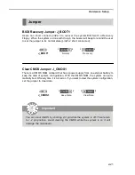
Page 37: ...data Jumper J_CMOS1 1 Important You can clear CMOS by shorting 2 3 pin while the system is off Then return to 1 2 pin position Avoid clearing the CMOS while the system is on it will damage the mainbo...

Page 38: ...sure that you unplug the power supply first Meanwhile read the documentation for the expansion card to configure any necessary hardware or software settings for the expan sion card such as jumpers swi...

Page 39: ...setting its jumper Refer to the hard disk documentation supplied by hard disk vendors for jumper setting instructions If you install one IDE device with ATA133 IDE cable and one CF device you must con...

Page 40: ......

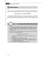
Page 41: ...IOS Setup program and allows you to configure the system for optimum use You may need to run the Setup program when An error message appears on the screen during the system booting up and requests you...

Page 42: ...PHOENIX 2nd 5th digit refers to the model number 6th digit refers to the chipset as I Intel N nVidia and V VIA 7th 8th digit refers to the customer as MS all standard customers V1 x refers to the BIOS...

Page 43: ...Then you can use the control keys to enter values and move from field to field within a sub menu If you want to return to the main menu just press the Esc General Help F1 The BIOS setup program provid...

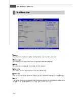
Page 44: ...eatures Boot Use this menu to specify the priority of boot devices Security Use this menu to set supervisor and user passwords Chipset This menu controls the advanced features of the onboard Northbrid...

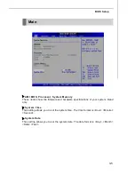
Page 45: ...show the firmware and hardware specifications of your system Read only System Time This setting allows you to set the system time The time format is Hour Minute Second System Date This setting allows...

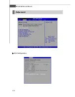
Page 46: ...3 6 MS 91A2 Server Board Advanced CPU Configuration...

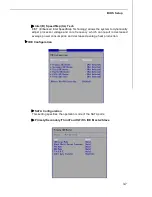
Page 47: ...dynamically adjust processor voltage and core frequency which can result in decreased average power consumption and decreased average heat production IDE Configuration SATA Configuration This setting...

Page 48: ...on except Disabled determines the number of sectors transferred per block PIO Mode Indicates the type of PIO Programmed Input Output DMA Mode Indicates the type of Ultra DMA S M A R T This allows you...

Page 49: ...expected each time the watch dog polls it Hardware Health Configuration These items display the current status of all of the monitored hardware devices components such as voltages temperatures and all...

Page 50: ...te Power On Leaves the computer in the power on state Last State Restores the system to the previous status before power failure or interrupt occurred Resume On PME When set to Enabled this setting al...

Page 51: ...Press Enter and a screen pops up asking users to confirm whether or not to clear all DMI event logs immediately Press Y and Enter the BIOS will clear all DMI event logs right away Clear Event Log When...

Page 52: ...e receiving device can handle all of the incoming data This is particularly important where the sending device is capable of sending data much faster than the receiving device can receive it Redirecti...

Page 53: ...seconds to display memory information USB Configuration Legacy USB Support Set to Enabled if you need to use any USB 1 1 2 0 device in the operating system that does not support or have any USB 1 1 2...

Page 54: ...Delay This setting controls the number of seconds the POST waits for the USB mass storage device after the start unit command is sent Emulation Type This setting enables you to set the type of device...

Page 55: ...3 15 BIOS Setup Boot Boot Settings Configuration...

Page 56: ...the system is powered on Setting to On will turn on the Num Lock key when the system is powered on Setting to Off will allow users to use the arrow keys on the numeric keypad PS 2 Mouse Support Selec...

Page 57: ...u may use the arrow keys to select the desired device then press or PageUp PageDown key to move it up down in the priority list Removable Drives 1st Drive 2nd Drive This setting allows users to set th...

Page 58: ...ord Supervisor Password controls access to the BIOS Setup utility These settings allow you to set or change the supervisor password User Password Change User Password User Password controls access to...

Page 59: ...Use these settings to specify whether the system will be awakened from power saving modes when activity or input signal of onboard LAN is detected PWRON LAN2 3 LAN4 5 Bypass Control PWROFF LAN2 3 LAN4...

Page 60: ...e Setup Utility Discard Changes Abandon all changes and continue with the Setup Utility Load Optimal Defaults Use this menu to load the default values set by the mainboard manufacturer specifi cally f...

Reviews: