background image

3-9

BIOS Setup

Boot Sequence

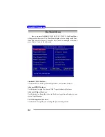
Press <Enter> and the following sub-menu appears.

1st/2nd/3rd

The items allow you to set the sequence of boot devices where AMIBIOS
attempts to load the operating system. The settings are:

IDE-0

The system will boot from the first HDD.

IDE-1

The system will boot from the second HDD.

IDE-2

The system will boot from the third HDD.

IDE-3

The system will boot from the fourth HDD.

Floppy

The system will boot from floppy drive.

ARMD-FDD

The system will boot from any ARMD device, such as
LS-120 or ZIP drive, that functions as a floppy drive.

ARMD-HDD

The system will boot from ARMD device, such as MO
or ZIP drive, that functions as hard disk drive.

CDROM

The system will boot from the CD-ROM.

Legacy SCSI

The system will boot from the SCSI.

Legacy Network


The system will boot from the Network drive.

BBS-0

The system will boot from the first BBS (BIOS Boot
Specification) compliant device.

BBS-1

The system will boot from the second BBS (BIOS Boot
Specification) compliant device.

BBS-2

The system will boot from the third BBS (BIOS Boot
Specification) compliant device.

BBS-3

The system will boot from the fourth BBS (BIOS Boot
Specification) compliant device.

USB FDD

The system will boot from USB-interfaced floppy drive.

USB CDROM

The system will boot from the USB-interfaced CD-ROM.

USB HDD

The system will boot from the USB-interfaced HDD.

USB RMD-FDD

 The system will boot from any USB-interfaced ARMD

device, such as LS-120 or ZIP drive, that functions as a
floppy drive.

Summary of Contents for 645 Combo

Page 1: ...i Version 1 0 G52 M6737X1 G22 MS 6737 v1 X ATX Mainboard 645 Combo...

Page 2: ...ith the instruction manual may cause harmful interference to radio communications Operation of this equipment in a residential area is likely to cause harmful interference in which case the user will...

Page 3: ...ration Windows 95 98 2000 NT XP are registered trademarks of Microsoft Corporation Netware is a registered trademark of Novell Inc Award is a registered trademark of Phoenix Technologies Ltd AMI is a...

Page 4: ...module 9 All cautions and warnings on the equipment should be noted 10 Never pour any liquid into the opening that could damage or cause electri cal shock 11 If any of the following situations arises...

Page 5: ...onitor 1 7 D Bracket 2 Optional 1 8 PC Alert 4 1 10 Chapter2 HardwareSetup 2 1 Quick Components Guide 2 2 Central Processing Unit CPU 2 3 CPU Core Speed Derivation Procedure 2 3 CPU Installation Proce...

Page 6: ...d Disk Connectors IDE1 IDE2 2 18 Fan Power Connectors CPUFA SYSFA 2 19 Front Panel Connectors JFP1 JFP2 2 20 Front Panel Audio Connector JAUD1 2 21 Front USB Connectors JUSB1 JUSB2 2 22 D Bracket 2 Co...

Page 7: ...Frequency Voltage Control 3 26 Set Supervisor User Password 3 28 Load Optimal High Performance Defaults 3 29 Appendix Using4 or6 ChannelAudioFunction A 1 Using 4 or 6 Channel Audio Function A 2 Insta...

Page 8: ...MS 6737 v1 X ATX mainboard The 645 Combo is based on SiS 645 962L chipsets for optimal system efficiency Designed to fit the ad vanced Intel Pentium 4 processors in 478 pin package the 645 Combo deliv...

Page 9: ...GA Dual IDE ATA 66 100 133 controllers Integrated USB 2 0 1 1 host controller and Fast Ethernet MAC controller Integrated audio controller with AC97 interface Advanced power management and PC2001 comp...

Page 10: ...with AC 97 v2 2 spec Meets PC2001 audio performance requirement LAN Optional hSiS962L integrated MAC RealTek 8201BL PHY Supports 10Mbps and 100Mbps auto negotiation operation Supports ACPI power manag...

Page 11: ...CONN1 IDE 1 IDE 2 Winbond W83697HF Top Mouse Bottom Keyboard T LAN Jack B USB Ports JCD1 Codec JBAT1 JDB1 FDD1 AGP Slot JUSB2 JUSB1 JFP1 JFP2 BATT SiS 962L SiS 645 PCI Slot 6 PCI Slot 5 PCI Slot 4 PC...

Page 12: ...To overclock the CPU FSB Front Side Bus frequency under the Windows operating system click FSB and use the right and left arrow keys to select the desired FSB and then click Apply to apply the new se...

Page 13: ...d the follow ing screen will appear Five buttons are placed on the leftmost pane of the screen Click the desired button to start the update process z z z z z Live BIOS Updates the BIOS online z z z z...

Page 14: ...will appear You can specify how often the system will automatically search for the BIOS drivers version or change the LAN settings right from the dialog box You can right click the MSI Live Monitor ic...

Page 15: ...This will start writing VGA sign on message to the screen 1 2 3 4 Red Green D Bracket 2 1 2 3 4 D Bracket 2 Optional D Bracket 2 is an external USB bracket integrating four Diagnostic LEDs which use g...

Page 16: ...ideo adapter BIOS Sign On This will start showing information about logo processor brand name etc Testing Base and Extended Memory Testing base memory from 240K to 640K and extended memory above 1MB u...

Page 17: ...al the program main screen will be immediately shown on the screen with the abnormal item highlighted in red This will continue to be shown until the condition returns to the normal status Users can u...

Page 18: ...below with information about the CPU and chipset Right click the mouse to select the skin you want to switch to Cute MSIRemindsYou 1 The new feature COOLER XP will work only if your mainboard supports...

Page 19: ...up procedures While doing the installation be careful in holding the components and follow the installation procedures For some components if you install in the wrong orientation the components will n...

Page 20: ...1 2 p 2 7 CONN1 p 2 10 SDIMM1 2 p 2 7 JUSB1 p 2 22 SYSFA p 2 19 JFP1 p 2 20 JFP2 p 2 20 JBAT1 p 2 24 JAUD1 p 2 21 PCI Slots p 2 25 AGP Slot p 2 25 JCD1 p 2 17 Back Panel I O p 2 12 CPU p 2 3 JUSB2 p...

Page 21: ...g This motherboard is designed to support overclocking However please make sure your components are able to toler ate such abnormal setting while doing overclocking Any at tempt to operate beyond prod...

Page 22: ...the socket and can not be seen Please note that any violation of the correct installation pro cedures may cause permanent damages to your mainboard 5 Press the CPU down firmly into the socket and clos...

Page 23: ...the CPU Follow the instructions below to install the Heatsink Fan 2 Position the heatsink onto the reten tion mechanism 1 Locate the CPU and its retention mechanism on the motherboard 3 Mount the fan...

Page 24: ...2 6 MS 6737 ATX Mainboard 5 Connect the fan power cable from the mounted fan to the 3 pin fan power connector on the board fan power cable NOTES...

Page 25: ...rate properly at least one DIMM module must be installed Memory MSI Reminds You Make sure that you install only one type of memory modules either SDR or DDR at one time DO NOT install both types at th...

Page 26: ...of module The mod ule will only fit in the right orientation 2 Insert the DIMM memory module vertically into the DIMM slot Then push it in until the golden finger on the memory module is deeply in se...

Page 27: ...R Module Combination At least one DIMM module should be installed on the motherboard Memory modules can be installed on the slots in any order The single double sided memory modules that each DIMM slo...

Page 28: ...onnector CONN1 This connector allows you to connect to an ATX power supply To con nect to the ATX power supply make sure the plug of the power supply is inserted in the proper orientation and the pins...

Page 29: ...d to provide power to the CPU ATX 5V 12V Power Connector JPW2 This 5V 12V power connector is used to provide power to the components on the mainboard JPW1 1 3 4 2 PIN SINGAL 1 5V 2 GND 3 GND 4 12V JPW...

Page 30: ...2 mouse You can plug a PS 2 mouse directly into this connector The connector location and pin assignments are as follows PIN SIGNAL DESCRIPTION 1 Mouse DATA Mouse DATA 2 NC No connection 3 GND Ground...

Page 31: ...Pin Definition PS 2 Keyboard 6 pin Female 2 1 3 4 5 6 USB Connectors The mainboard provides a OHCI Open Host Controller Interface Uni versal Serial Bus root for attaching USB devices such as keyboard...

Page 32: ...t or Transmit Data 4 DTR Data Terminal Ready 5 GND Ground 6 DSR Data Set Ready 7 RTS Request To Send 8 CTS Clear To Send 9 RI Ring Indicate Pin Definition 9 Pin Male DIN Connector 1 2 3 4 5 6 7 8 9 RJ...

Page 33: ...ode 13 1 14 25 PIN SIGNAL DESCRIPTION 1 STROBE Strobe 2 DATA0 Data0 3 DATA1 Data1 4 DATA2 Data2 5 DATA3 Data3 6 DATA4 Data4 7 DATA5 Data5 8 DATA6 Data6 9 DATA7 Data7 10 ACK Acknowledge 11 BUSY Busy 12...

Page 34: ...Connectors Line Out Line In MIC Joystick Midi Connector You can connect a joystick or game pad to this connector MSI Reminds You For advanced audio application RealTek ALC650 audio chip is provided to...

Page 35: ...LAN USB Ports and CPU System fans Floppy Disk Drive Connector FDD1 The mainboard provides a standard floppy disk drive connector that supports 360K 720K 1 2M 1 44M and 2 88M floppy disk types Connecto...

Page 36: ...33 controller that provides PIO mode 0 4 Bus Master and Ultra DMA 33 66 100 133 function You can connect up to four hard disk drives CD ROM 120MB Floppy reserved for future BIOS and other devices Thes...

Page 37: ...ways take note that the red wire is the positive and should be connected to the 12V the black wire is Ground and should be connected to GND If the mainboard has a System Hardware Monitor chipset on bo...

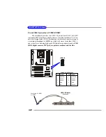
Page 38: ...pull up 8 PWR_SW_N Power Switch low reference pull down to GND 9 RSVD_DNU Reserved Do not use JFP1 Pin Definition PIN SIGNAL PIN SIGNAL 1 GND 2 SPK 3 SLED 4 BUZ 5 PLED 6 BUZ 7 NC 8 SPK JFP2 Pin Defin...

Page 39: ...circuits 5 AUD_FPOUT_R Right channel audio signal to front panel 6 AUD_RET_R Right channel audio signal return from front panel 7 HP_ON Reserved for future use to control headphone amplifier 8 KEY No...

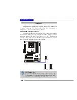
Page 40: ...B 2 0 technology increases data transfer rate up to a maximum throughput of 480Mbps which is 40 times faster than USB 1 1 and is ideal for connecting high speed USB interface peripherals such as USB H...

Page 41: ...arious combinations of LED signals For definitions of 16 signal combinations please refer to D Bracket 2 Optional in Chapter 1 JDB1 1 9 2 10 Pin Signal 1 DBG1 high for green color 2 DBR1 high for red...

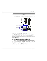
Page 42: ...ttery to keep the data of system configuration With the CMOS RAM the system can automatically boot OS every time it is turned on If you want to clear the system configuration use the JBAT1 Clear CMOS...

Page 43: ...It introduces a 66MHz 32 bit channel for the graphics controller to directly access main memory PCI Peripheral Component Interconnect Slots The PCI slots allow you to insert the expansion cards to me...

Page 44: ...interrupt signals to the microprocessor The PCI IRQ pins are typically connected to the PCI bus INT A INT D pins as follows Order 1 Order 2 Order 3 Order 4 PCI Slot 1 INT B INT C INT D INT A PCI Slot...

Page 45: ...tup pro gram and allows you to configure the system for optimum use You may need to run the Setup program when An error message appears on the screen during the system booting up and requests you to r...

Page 46: ...ility by pressing F11 When the same message as listed above appears on the screen press F11 to trigger the boot menu The POST messages might pass by too quickly for you to respond in time If so restar...

Page 47: ...d the system MSI Reminds You The items under each BIOS category described in this chapter are under continuous update for better system performance Therefore the description may be slightly different...

Page 48: ...pset Features Use this menu to change the values in the chipset registers and optimize your system s performance Power Management Features Use this menu to specify your settings for power management O...

Page 49: ...your settings for frequency voltage control Set Supervisor Password Use this menu to set Supervisor Password Set User Password Use this menu to set User Password Load Optimal Defaults Use this menu t...

Page 50: ...alue you prefer System Time This allows you to set the system time that you want usually the current time The time format is hour minute second System Date This allows you to set the system to the dat...

Page 51: ...ector number Maximum Capacity Read the maximal HDD capacity LBA Mode Select Auto for a hard disk 512 MB un der Windows and DOS or Disabled un der Netware and UNIX Block Mode Select Auto to enhance the...

Page 52: ...to show the company logo on the bootup screen Setting options Disabled Shows the POST messages at boot Enabled Shows a still image logo on the full screen at boot Anti Virus Protection The item is to...

Page 53: ...nctions as hard disk drive CDROM The system will boot from the CD ROM Legacy SCSI The system will boot from the SCSI Legacy Network The system will boot from the Network drive BBS 0 The system will bo...

Page 54: ...Up Num Lock LED This item is to set the Num Lock status when the system is powered on Set ting to On will turn on the Num Lock key when the system is powered on Setting to Off will allow end users to...

Page 55: ...Write Thru WriteBack WriteThru refer to the cache s write policy which determines how it handles writes to memory locations that are currently being held in cache The WriteBack cache policy will prod...

Page 56: ...rmance while 2 5T provides more stable system performance Setting to By SPD enables DRAM CAS Latency automatically to be determined by BIOS based on the configurations of the SPD Serial Presence Detec...

Page 57: ...ng on the system memory installed MA 1T 2T Select This setting controls the SDRAM command rate Setting to Auto allows the the SDRAM command rate to be determined by the BIOS Selecting MA 1T MA 2T make...

Page 58: ...ions Disabled Enabled Sleep State This item specifies the power saving modes for ACPI function If your oper ating system supports ACPI such as Windows 98SE 2000 ME XP you can choose to enter the Stand...

Page 59: ...efore if the AGP driver of the card does not support the initialization feature the display may work abnormally or not function after resuming from S3 Suspend Time Out After the selected period of sys...

Page 60: ...e only one Power On event If set to Password please press Enter to input password and its maximum pass word is 5 character Setting options Disabled Any Key Specific Key Password Wake Up By PS 2 Mouse...

Page 61: ...ttings Enabled Disabled Alarm Date Hour Minute Second If Resume By Alarm is set to Enabled the system will automatically resume boot up on a specific date hour minute second specified in these fields...

Page 62: ...changes to the default settings Clear ESCD The ESCD Extended System Configuration Data NVRAM Non volatile Random Access Memory is where the BIOS stores resource information for both PNP and non PNP d...

Page 63: ...IRQ line for each PCI slot Set IRQs to PCI or ISA Press Enter to enter the sub menu and the following screen appears IRQ 3 4 5 7 9 10 11 14 15 These items specify the bus where the specified IRQ line...

Page 64: ...IDE IRQ 9 will still be available for PCI and PnP devices available settings ISA EISA and PCI PnP Set DMAs to PnP or ISA Press Enter to enter the sub menu and the following screen appears DMA Channel...

Page 65: ...imes faster than USB 1 1 and is ideal for connecting high speed USB interface peripherals such as USB HDD digital cameras MP3 players printers modems and the like Setting options Disabled Enabled USB...

Page 66: ...ation of the onboard LAN Boot ROM during bootup Selecting Disabled will speed up the boot process Onboard PCI IDE This setting controls the onboard PCI IDE controllers Setting options Disabled Primiar...

Page 67: ...allel port if the port is set to EPP mode Settings EPP1 7 and EPP1 9 Parallel Port IRQ When Parallel Port is set to Auto the item shows Auto indicating that BIOS determines the IRQ for the parallel po...

Page 68: ...V 5 0V 12V 12V 5 0V Battery Voltage System CPU Fan Speed System CPU Temperature These items display the current status of all of the monitored hardware de vices components such as system voltages temp...

Page 69: ...d to flatter curves If you do not have any EMI problem leave the setting at Disabled for optimal system stability and performance But if you are plagued by EMI setting to Enabled for EMI reduction Rem...

Page 70: ...Front Side Bus clock frequency and only works if the Detect CPU FSB Clock setting is set to Disabled CPU DRAM Clock Ratio This setting controls the ratio of CPU FSB Clock DRAM Frequency to enable the...

Page 71: ...hen a password has been set you will be prompted to enter it every time you try to enter Setup This prevents an unauthorized person from chang ing any part of your system configuration Additionally wh...

Page 72: ...ad High Performance Defaults a message as below appears Pressing Enter loads the default BIOS values that enable the best system performance but may lead to a stability issue Load Optimal High Perform...

Page 73: ...t for 6 channel audio output including 2 Front 2 Rear 1 Center and 1 Subwoofer channel ALC650 allows the board to attach 4 or 6 speakers for better surround sound effect The section will tell you how...

Page 74: ...tput function if a proper setting is made in the software utility Read the following steps to have the Multi Channel Audio Function properly set in the software utility and have your speakers correctl...

Page 75: ...A 3 Using 4 or 6 Channel Audio Function 5 6 4 2 3...

Page 76: ...responding multi channel operation from No of Speakers Refer to the following diagram and caption for the founction of each jack on the back panel when 4 Channel Mode is selected 1 Line Out Front chan...

Page 77: ...r and Subwoofer channel Both Line In and MIC function are converted to Line Out function when 4 Channel Mode for 6 Speaker Output is selected 6 Channel Mode for 6 Speaker Output Refer to the following...

Page 78: ...esting Each Speaker 1 Click the audio icon from the window tray at the lower right corner of the screen 2 Click the Speaker Test tab 3 The following window appears Select the speaker which you want to...

Page 79: ...Function 4 While you are testing the speakers in 6 Channel mode if the sound coming from the center speaker and subwoofer is swapped you should select Swap Center Subwoofer Output to readjust these tw...

Page 80: ...function applies only to 2 channel audio operation so make sure 2 Channel Mode is selected in the No of Speakers column before playing KaraOK Playing KaraOK 1 Click the audio icon from the window tray...

Page 81: ...BIOS whileIsee Award BIOS duringsystemboot up A Phoenix Award already merged as one company All MSI motherboards using Award BIOS come with Phoenix logo stickers Q HowdoIknowwhatMSID LEDorD bracketlig...

Page 82: ...owing suggestions 1 Dont install zonealarm 2 Disable WebTrap of PC cillion 2000 3 Disable any web based anti virus Software Q Can Live Update Series support WinXP A Live Update Series version 215 can...

Page 83: ...Sversion A Upon boot up the 1st line appearing after the memory count is the BIOS version It is usually in the format 1 For older model number AG76091096where 1stdigitreferstoBIOSmakerasA AMI R W AWAR...

Page 84: ...s and hold Ctrl Home to force update It will read the AMIBOOT ROM file and recover the BIOS from the A drive When 4 beeps are heard you may remove the floppy disk and restart the computer For Award BI...

Page 85: ...unused frequency band of 2 45 GHz that is available globally with some variation of bandwidth in different countries In addition to data up to three voice channels are available Each device has a uni...

Page 86: ...y circuits for transmitting and receiv ing data a PC chipset provides the electronic interfaces between all subsystems Clock Cycle Clock cycle or tick is the smallest unit of time recognized by a devi...

Page 87: ...mass storage devices of up to 8 4 gigabytes whereas the old standard was limited to 528 MB Because of its lower cost enhanced EIDE has replaced SCSI in many areas There are four EIDE modes defined The...

Page 88: ...rrupt Request Line IRQs are hardware lines over which devices can send interrupt signals to the microprocessor When you add a new device to a PC you sometimes need to set its IRQ number by setting a D...

Page 89: ...s LPT1 LPT2 and LPT3 It is frequently used by the OS to identify a printer Overclocking Overclocking is resetting your computer so that the microprocessor runs faster than the manufacturer specified s...

Page 90: ...vices to computers SCSI interfaces provide for faster data transmission rates up to 80 megabytes per second than standard serial and parallel ports In addition you can attach many devices to a single...

Reviews: