background image

Gettng Started

MS-7596

1-5

Gettng Started

MS-7596

MSI manboard

MSI Drver/Utlty DVD

SATA Cable (Optonal)

Power Cable

USB Bracket (Optonal)

Standard Cable for  

IDE Devces

Back IO Sheld

User’s Gude

p

acking

 c

heckLiSt

* The pctures are for reference only and may vary from the packng contents of the 

product you purchased. If you need to purchase accessores and request the part num-

bers,  you  could  search  the  product  web  page  and  find  detals  on  our  web  address 

http://www.ms.com/ndex.php

Summary of Contents for 760GM

Page 1: ...785GM E51 760GM E51 series MS 7596 v1 x Mainboard G52 75961XB...

Page 2: ...Microsoft Corporation AMI is registered trademark of American Megatrends Inc Award is a registered trademark of Phoenix Technologies Ltd Sound Blaster is registered trademark of Creative Technology L...

Page 3: ...rnings on the equipment should be noted Never pour any liquid into the opening that could damage or cause electrical shock If any of the following situations arises get the equipment checked by servic...

Page 4: ...ct the interference by one or more of the measures listed below Reorient or relocate the receiving antenna Increase the separation between the equipment and receiver Connect the equipment into an outl...

Page 5: ...k Altger te nicht mehr als kommunale Abf lle entsorgt werden MSI hat europaweit verschiedene Sammel und Recyclingunternehmen beauftragt die in die Europ ische Union in Verkehr gebrachten Produkte am E...

Page 6: ...e producten die de merknaam MSI dragen en verkocht zijn in de EU Deze goederen kunnen geretourneerd worden op lokale inzamelingspunten SRPSKI Da bi za titili prirodnu sredinu i kao preduze e koje vodi...

Page 7: ...h sb rn ch MAGYAR Annak rdek ben hogy k rnyezet nket megv dj k illetve k rnyezetv d k nt fell pve az MSI eml kezteti nt hogy Az Eur pai Uni EU 2005 augusztus 13 n hat lyba l p az elektromos s elek tro...

Page 8: ...Layout 1 4 Packing Checklist 1 5 Chapter 2 Hardware Setup 2 1 Quick Components Guide 2 2 CPU Central Processing Unit 2 3 Memory 2 6 Power Supply 2 8 Back Panel 2 9 Connectors 2 11 Jumpers 2 18 Switch...

Page 9: ...ts 3 28 Appendix A Realtek Audio A 1 Installing the Realtek HD Audio Driver A 2 Software Configuration A 4 Hardware Setup A 19 Appendix B SB710 RAID B 1 RAID Configuration B 2 Appendix C Overclocking...

Page 10: ...5GM E51 760GM E51 Series mainboards are based on AMD 785G 760G SB710 chipsets for optimal sys tem efficiency Designed to fit the advanced AMD 64 bits PhenomTM II processor the 785GM E51 760GM E51 Seri...

Page 11: ...et Share Memory Max up to 512MB Memory Support DDR3 1333 1066 800 SDRAM total 16 GB Max 4 DDR3 DIMMs 240 pin 1 5V For more information on compatible components please visit http www msi com index php...

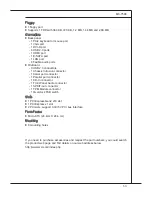
Page 12: ...ctor 1 Serial port connector 1 Parallel port connector 1 CD In connector 1 Front Panel Audio connector 1 SPDIF out connector 1 TPM Module connector 1 Overclock FSB switch Slots 1 PCI Express Gen2 x16...

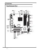
Page 13: ...1 4 Getting Started Getting Started 785GM E51 760GM E51 Series MS 7596 v1 X Mainboard Mainboard Layout...

Page 14: ...IDE Devices Back IO Shield User s Guide Packing Checklist The pictures are for reference only and may vary from the packing contents of the product you purchased If you need to purchase accessories an...

Page 15: ......

Page 16: ...ion be careful in holding the components and follow the installation procedures For some components if you install in the wrong orientation the components will not work properly Use a grounded wrist s...

Page 17: ...anel p 2 9 CPU p 2 3 CPUFAN p 2 13 DDR3 p 2 6 JCOM1 p 2 16 JCI1 p 2 12 JLPT1 p 2 16 FDD1 p 2 11 JPWR1 p 2 8 IDE1 p 2 11 JTPM1 p 2 17 SATA p 2 12 SYSFAN p 2 13 JFP1 p 2 14 JUSB1 3 p 2 15 JBAT1 p 2 18 J...

Page 18: ...ting Make sure that you apply an even layer of thermal paste or thermal tape between the CPU and the heatsink to enhance heat dissipation Replacing the CPU While replacing the CPU always turn off the...

Page 19: ...y embedded into the socket and can not be seen Please note that any violation of the correct installation procedures may cause permanent damages to your mainboard 3 Press the CPU down firmly into the...

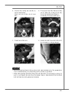
Page 20: ...e on your fingers because once the Safety Hook is disconnected from the fixed bolt the fixed lever will spring back instantly Position the cooling set onto the re tention mechanism Hook one end of the...

Page 21: ...explain the population rules for Dual Channel mode 1 DIMM1 DIMM2 DIMM3 DIMM4 2 DIMM1 DIMM2 DIMM3 DIMM4 Installed Empty Important DDR3 memory modules are not interchangeable with DDR2 and the DDR3 stan...

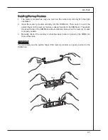
Page 22: ...til the golden finger on the memory module is deeply inserted in the DIMM slot The plastic clip at each side of the DIMM slot will automatically close when the memory module is properly seated Manuall...

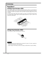
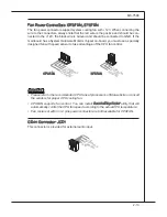
Page 23: ...ply along with pin 1 pin 13 refer to the image at the right hand 1 3 3 3 V 1 3 3 V 1 4 1 2 V 2 3 3 V 1 5 G r o u n d 3 G r o u n d 1 6 P S O N 4 5 V 1 7 G r o u n d 5 G r o u n d 1 8 G r o u n d 6 5 V...

Page 24: ...s properly connected to your monitor refer to your monitor manual for more information USB Port The USB Universal Serial Bus port is for attaching USB devices such as keyboard mouse or other USB compa...

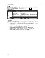
Page 25: ...Mbits sec data rate is selected Orange On 1000 Mbits sec data rate is selected Audio Ports These audio connectors are used for audio devices It is easy to differentiate between audio effects according...

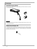
Page 26: ...f f a sd f d d d d d d d fd a sf d a sa sd f a s d a sd a sd d d d d d d f a s a s d fs d ff sd f a d f f f a s d f f f d f F l o p p y D M S I F l o p p y D M S I K dk l k dk fk kk f d kk l dd f k k...

Page 27: ...k f d k k l d d f k k k sd d f d d f a sd k a d f d d fd d a d d fd fd d d d d fa d f a d k j a sj d k d f d f a sd d d ff a sd fd d d d d d d fd a sf d a s as d f a sd a sd a sd d d d d d d f a s a s...

Page 28: ...take advantage of the CPU fan control 1 G r o u n d 2 1 2 V 3 S e n s o r 4 C o n t r o l 1 G r o u n d 2 1 2 V 3 S e n s o r CPUFAN SYSFAN Important Please refer to the recommended CPU fans at proces...

Page 29: ...tel Front Panel I O Connectivity Design Guide 1 3 1 0 N o P i n 5 R e s e t S w i t c h H D D L E D P o w e r S w i t c h P o w e r L E D 7 9 R e s e r v e d 8 6 4 2 S PDIF Out Connector JSP1 This con...

Page 30: ...D 7 G r o u n d 9 N o P i n 8 G r o u n d 6 U S B D 4 U S B D 2 V C C Important Note that the pins of VCC and GND must be connected correctly to avoid possible damage Front Panel Audio Connector JAUD1...

Page 31: ...ed to connect an optional parallel port bracket The parallel port is a standard printer port that supports Enhanced Parallel Port EPP and Extended Capa bilities Parallel Port ECP mode 1 0 G r o u n d...

Page 32: ...for more details and usages 1 0 N o P i n 1 4 G r o u n d 8 5 V P o w e r 1 2 G r o u n d 6 S e r i a l I R Q 4 3 3 V P o w e r 2 3 V S t a n d b y p o w e r 1 L P C C l o c k 3 L P C R e s e t 5 L P...

Page 33: ...ation With the CMOS RAM the system can automati cally boot OS every time it is turned on If you want to clear the system configuration set the jumper to clear data JBAT1 Keep Data Clear Data 1 1 1 Imp...

Page 34: ...FSB Switch OCSWITCH1 You can overclock the FSB to increase the processor frequency by changing the switch Follow the instructions below to set the FSB Default Increase 10 speed of FSB Increase 15 spee...

Page 35: ...ut to a single display for blisteringly fast frame rates Unleash the graphics performance System Request Hybrid CrossFireX is only supported with the Vista operating system Graphic card based on an AT...

Page 36: ...cards in the configuration as are all displays except the one used by Hybrid CrossFireX More details please refer to http game amd com us en crossfirex_hybrid aspx Important Changing integrated graphi...

Page 37: ...the documentation for the expansion card to configure any necessary hardware or software settings for the expansion card such as jumpers switches or BIOS configuration PCI Interrupt Request Routing T...

Page 38: ...ndicators CPU Phase LEDs LED1 LED2 LED3 LED4 These LEDs indicate the current CPU power phase mode Follow the instructions below to read Blue light Off LED1 LED2 LED3 LED4 Mode CPU is in 1 phase power...

Page 39: ......
Page 40: ...ws you to configure the system for op timum use You may need to run the Setup program when An error message appears on the screen during the system booting up and requests you to run SETUP You want to...

Page 41: ...s under each BIOS category described in this chapter are under continuous update for better system performance Therefore the description may be slightly dif ferent from the latest BIOS and should be h...

Page 42: ...he item The on line description of the highlighted setup function is displayed at the bottom of the screen Sub Menu If you find a right pointer symbol as shown in the right view ap pears to the left o...

Page 43: ...ated Peripherals Use this menu to specify your settings for integrated peripherals Power Management Setup Use this menu to specify your settings for power management H W Monitor This entry shows your...

Page 44: ...OS Load Fail Safe Defaults Use this menu to load the default values set by the BIOS vendor for stable system performance Load Optimized Defaults Use this menu to load the default values set by the mai...

Page 45: ...his allows you to set the system to the date that you want usually the current date The format is day month date year day Day of the week from Sun to Sat determined by BIOS Read only month The month f...

Page 46: ...isabled DMA Mode Select DMA Mode Hard Disk S M A R T This allows you to activate the S M A R T Self Monitoring Analysis Reporting Technology capability for the hard disks S M A R T is a utility that m...

Page 47: ...will halt on for 15 seconds and then automatically resume its operation All Error The system stops when any error is detected No Error The system does not stop for any detected error System Informatio...

Page 48: ...BIOS After updating the BIOS you should immediately re enable it to protect it against viruses Full Screen Logo Display This item enables this system to show the company logo on the boot up screen Se...

Page 49: ...y graphics adapter PCI Latency Timer This item controls how long each PCI device can hold the bus before another takes over When set to higher values every PCI device can conduct transactions for a lo...

Page 50: ...ect the location of UMA to avoid over lapping with the other data blocks in system memory Boot Sequence Press Enter to enter the sub menu and the following screen appears 1st Boot Device This item all...

Page 51: ...SB interfaced device in the operating system Onboard LAN Controller This setting allows you to enable disable the onboard LAN controller LAN Option ROM This item is used to decide whether to invoke th...

Page 52: ...board Super I O chipset that provides Stan dard ECP and EPP features It has the following options Disabled 3BC IRQ7 Line Printer port 0 278 IRQ5 Line Printer port 2 378 IRQ7 Line Printer port 1 Paral...

Page 53: ...f your operating system supports ACPI such as Windows 2000 XP you can choose to enter the Standby mode in S1 POS or S3 STR fashion through the setting of this field Settings are S1 The S1 sleep mode i...

Page 54: ...ke Up Event By Setting to BIOS activates the following fields and use the following fields to set the wake up events Setting to OS the wake up events will be defined by OS Resume From S3 By USB Device...

Page 55: ...automatically depending on the current temperature to keep it with in a specific range You can enable a fan target value here If the current CPU fan temperature reaches to the target value the smart...

Page 56: ...MS 7596 3 17 MS 7596 Green Power CPU LED Phase Control When it set to Enabled the AMD Cool and Quite was be force enable...

Page 57: ...ord and press Enter You may also press Esc to abort the selection and not enter a password To clear a set password just press Enter when you are prompted to enter the pass word A message will show up...

Page 58: ...you are familiar with the chipset Current CPU DRAM Frequency These items show the current clocks of CPU and Memory speed Read only CPU Specifications Press Enter to enter the sub menu and the followi...

Page 59: ...y and dynamically lower CPU speed and power consumption Important To ensure that Cool n Quiet function is activated and will be working properly it is required to double con firm that Run BIOS Setup a...

Page 60: ...pports this function Auto OverClock Technology Setting this item to Max FSB allows the system to detect the FSB limitation for over clocking automatically If overclocking fails you can try the lower F...

Page 61: ...Mode This feature is used to Integrate two 64 bit DCTs into a 128 bit interface Bank Interleaving Bank Interleaving is an important parameter for improving overclocking capability of memory It allows...

Page 62: ...e V DRAM Voltage V NB Voltage V HT Link Voltage V SB Voltage V These items are used to adjust the voltage of CPU Memory and chipset Spread Spectrum When the mainboard s clock generator pulses the extr...

Page 63: ...BIOS via the USB Storage drive directly Update BIOS ROM chip data from selected file which was be download from official website and must be saved in the root directory of the USB Stor age drive It o...

Page 64: ...efer to the block diagram below about the M Flash function Due to the special design of some graphics cards will cause dark screen during M flash operation and you may refer the beeps from the system...

Page 65: ...ific USB drive storage drive to save BIOS file from BIOS ROM chip data Note it only supports FAT FAT32 file system drive Save File Name as Please setup a specific name for the BIOS file which will be...

Page 66: ...ve Settings 1 2 3 4 These items are used to save the settings set by yourself to CMOS Load Settings 1 2 3 4 These items are available after you save your settings in Save Settings 1 2 3 4 items and ar...

Page 67: ...timal performance of the mainboard The Fail Safe Defaults are the default values set by the BIOS vendor for stable system performance When you select Load Fail Safe Defaults a message as below appears...

Page 68: ...provides 10 channel DAC that simul taneously supports 7 1 sound playback and 2 channels of independent stereo sound output multiple streaming through the Front Out Left and Front Out Right chan nels A...

Page 69: ...r later before installing the driver The following illustrations are based on Windows XP environment and could look slightly different if you install the drivers in different operating systems Insert...

Page 70: ...A 3 MS 7596 Click Next to install the Realtek High Definition Audio Driver 3 Click Finish to restart the system 4 Click here Select this option Click here Click here...

Page 71: ...use the 2 4 6 or 8 channel audio feature now Click the audio icon from the system tray at the lower right corner of the screen to activate the HD Audio Configuration It is also available to enable the...

Page 72: ...dor Bathroom Sewer pipe Arena and Auditorium for quick enjoyment You may choose the provided sound effects and the equalizer will adjust automatically If you like you may also load an equalizer settin...

Page 73: ...he settings are saved perma nently for future use Load Whenever you would like to use preload settings simply click this the whole list will be shown for your selection Enable Disable To disable you c...

Page 74: ...in Others you will find more optimized settings available to you Karaoke Mode Karaoke mode brings Karaoke fun back home Simply using the music you usually play Karaoke mode can help you eliminate the...

Page 75: ...ter you pluging the speakers into the jacks on the front panel Multi Stream Function Realtek audio supports an outstanding feature called Multi Stream which means you may play different audio sources...

Page 76: ...the rear panel which is the default setting Then you must to select the Realtek HD Audio 2nd output from the scroll list first and use a different program to play the second audio source for example...

Page 77: ...single or multiple volume controls or to completely mute sound output Tool Show the following volume controls This is to let you freely decide which volume control items to be displayed Advanced contr...

Page 78: ...ompletely mute sound input Tool Show the following volume controls This is to let you freely decide which volume control items to be displayed Enable recording multi streaming Important Realtek audio...

Page 79: ...aker for 5 1 Speaker Output 8CH Speaker for 7 1 Speaker Output Speaker Configuration Plug the speakers in the corresponding jack Dialogue connected device will pop up for your selection Please select...

Page 80: ...ront panel Please check if front jacks on your system are so called AC 97 jacks If so please check this item to disable front panel jack detection Mute rear panel output when front headphone plugged i...

Page 81: ...he signal from degrading when it is converted to analog Output Sampling Rate 44 1KHz This is recommend while playing CD 48KHz This is recommended while playing DVD or Dolby 96KHz This is recommended w...

Page 82: ...make testing sound If any speaker fails to make sound then check whether the cable is inserted firmly to the connector or replace the bad speakers with good ones Or you may click the auto test button...

Page 83: ...m being recorded by micro phone together with your sound For example you might have chance to use VOIP function through Internet with your friends The voice of your friend will come out from speakers...

Page 84: ...596 3D Audio Demo In this tab you may adjust your 3D positional audio before playing 3D audio applications like gaming You may also select different environment to choose the most suitable environment...

Page 85: ...udio Controller Audio Codec You may also select the language of this utility by choosing from the Language list Also there is a selection Show icon in system tray Switch it on and an icon will show in...

Page 86: ...nnel Audio Function mode properly in the software utility connect your speakers to the correct phone jacks in accordance with the setting in software utility 2 Channel Mode for Stereo Speaker Output L...

Page 87: ...A 20 Realtek Audio 4 Channel Mode for Stereo Speaker Output Line In Line Out Front channels MIC Line Out Rear channels No function No function 1 2 3 4 5 6...

Page 88: ...A 21 MS 7596 6 Channel Mode for Stereo Speaker Output Line In Line Out Front channels MIC Line Out Rear channels Line Out Center and Subwoofer channel No function 1 2 3 4 5 6...

Page 89: ...ls MIC Line Out Rear channels Line Out Center and Subwoofer channel Line Out Side channels Important To enable 7 1 channel audio out function on Windows Vista operating system you have to install the...

Page 90: ...g data across multiple drives RAID 1 makes sure data is not lost if a drive fails as data is simultaneously written to two drives Drives configured for RAID Striping are said to form a RAID 0 set whil...

Page 91: ...ID BIOS During boot up a screen similar to the one below will appear for about few seconds Press Ctrl F to enter FastBuild utility Important Be sure to enable the RAID function for SATA device in BIOS...

Page 92: ...MS 7596 B 3 MS 7596 View Drives Assignments This window displays the model number capacities and assignment of the drives physi cally attached to the SATA host adapter...

Page 93: ...f the system and plan the data storage strategy RAID sets can be created either automatically or to allow the greatest flexibility manually Press 2 on the Main Menu screen to enter the Define LD Menu...

Page 94: ...e arrow key to choose the hard drives which you want to make part of the LD use the space key to change the assignment to Y Then press Ctrl Y to save the configuration 4 A message will show up on the...

Page 95: ...tion is done the screen shows the LD information as below Press ESC key to the main screen 6 Press ESC key to exit the utility a message System is going to REBOOT Are You Sure will display answer Y to...

Page 96: ...D on the main screen Choose a LD No you want to delete and press Del or Alt D delete the RAID set 1 2 On the next screen a message will display to inform you press Ctrl Y to delete the RAID set or oth...

Page 97: ...es Drivers SBDrv SB7xx RAID x86 for 32bit or x64 for 64bit The driver disk for RAID controller is done For Windows Vista During the Operating system installation after selecting the location to instal...

Page 98: ...table RAID Array Insert the MSI DVD into the DVD ROM drive The DVD will auto run and the setup screen will appear Under the Driver tab click on AMD chipset drivers by your need The AMD chipset drivers...

Page 99: ...e hardware status of MSI Mainboard in windows such as CPU clock voltage fan speed and temperature Before you install the Overclocking Center please make sure the system has meet the following requirem...

Page 100: ...ing with your mainboard path Utility MSI Utility Over clocking Center it will have a short cut icon on the desktop and a short cut path in your Start up menu You may double click on each icon to activ...

Page 101: ...y PCI Motherboard Click Motherboard to read the information of motherboard BIOS installed CPU and installed graphics card Important The pictures in this appendix are for reference only and may vary fr...

Page 102: ...ocking Center Memory Click Memory to read the information of each memory DIMM slot You can select a DIMM slot you want to read from the SPD list PCI Click PCI to read the information of devices on the...

Page 103: ...ck ing in Advance menu Novice In the Novice menu it provides one default setting and several common settings for different environments You may choose one of the settings that you need The settings in...

Page 104: ...dvance menu you can adjust the values for each environment setting default setting Click the Cooling Silence Default Game Cinema button to enter it s setting menu Please refer to the following descrip...

Page 105: ...the button then select a value Click the arrow sign and the drop down menu will appear In the System Warning block you can set the maximum CPU system temperature and the minimum CPU system fan speed...

Page 106: ...Important It provides you to save up to 20 user settings Click the Load button and choose a saved user setting to load the settings for the sys tem Click the Load button and choose a saved user settin...

Reviews: