background image

2-25

Hardware  Setup

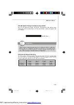
PCI Interrupt Request Routing

The IRQ, acronym of interrupt request line and pronounced I-R-Q, are hardware lines

over which devices can send interrupt signals to the microprocessor. The PCI IRQ

pins are typically connected to the PCI bus pins as follows:

Order 1

Order 2

Order 3

Order 4

PCI Slot 1

INT A#

INT B#

INT C#

INT D#

PCI Slot 2

INT B#

INT C#

INT D#

INT A#

32-bit PCI Slot

PCI (Peripheral Component Interconnect) Slot

The PCI slot supports LAN cards, SCSI cards, USB cards, and other add-on cards

that comply with PCI specifications. At 32 bits and 33 MHz, it yields a throughput rate

of 133 MBps.

Important

When  adding or removing expansion cards, make sure that  you unplug the
power supply first. Meanwhile, read the documentation for the expansion card
to configure any necessary hardware or software settings for the expansion
card, such as  jumpers, switches or BIOS  configuration.

7576v1.0-2.p65

2009/2/11, 

上午

 11:27

25

PDF created with pdfFactory trial version 

www.pdffactory.com

Summary of Contents for 790GX-G65 - SocketAM3/140W CPU/AMD 790GX

Page 1: ...790GX G65 series MS 7576 v1 X Mainboard G52 75761X1 7576v1 0 0 Preface p65 2009 2 11 11 27 1 PDF created with pdfFactory trial version www pdffactory com...

Page 2: ...registered trademarks of International Business Machines Corporation Windows XP Vista are registered trademarks of Microsoft Corporation Netware is a registered trademark of Novell Inc Award is a regi...

Page 3: ...tep on it Do not place anything over the power cord 8 Always Unplug the Power Cord before inserting any add on card or module 9 All cautions and warnings on the equipment should be noted 10 Never pour...

Page 4: ...below Reorient or relocate the receiving antenna Increase the separation between the equipment and receiver Connect the equipment into an outlet on a circuit different from that to which the receiver...

Page 5: ...v WEEE Waste Electrical and Electronic Equipment Statement 7576v1 0 0 Preface p65 2009 2 11 11 27 5 PDF created with pdfFactory trial version www pdffactory com...
Page 6: ...vi 7576v1 0 0 Preface p65 2009 2 11 11 27 6 PDF created with pdfFactory trial version www pdffactory com...

Page 7: ...vii 7576v1 0 0 Preface p65 2009 2 11 11 27 7 PDF created with pdfFactory trial version www pdffactory com...

Page 8: ...2 6 Power Supply 2 8 Back Panel 2 9 Connectors 2 11 Buttons 2 18 Switch 2 19 Slots 2 20 Chapter 3 BIOS Setup 3 1 Entering Setup 3 2 The Main Menu 3 4 Standard CMOS Features 3 6 Advanced BIOS Features...

Page 9: ...ing Center B 1 Activating Overclocking Center B 2 System Info B 3 DOT B 5 Appendix C SATA RAID C 1 RAID Configuration C 2 7576v1 0 0 Preface p65 2009 2 11 11 27 9 PDF created with pdfFactory trial ver...

Page 10: ...es mainboards are based on AMD 790GX 780G SB710 SB750 chipset for optimal system efficiency Designed to fit the advanced 64bit AMD Phenom II processor the 790GX G65 Series deliver a high performance a...

Page 11: ...tw index php func testreport Side Port Memory DDR3 SDRAM 1Gbit optional LAN Supports LAN 10 100 1000 Fast Ethernet by RTL8111DL IEEE 1394 optional Chip integrated by VIA VT6315N Transfer rate is up to...

Page 12: ...Switch pinheader 1 Serial port connector 1 TPM pinheader optional 1 OC switch 1 Power LED Button 1 Reset LED Button 1 Clear CMOS Button Slots For 790GX 1 PCI Express x16 slot supports up to PCI Expre...

Page 13: ...B3 JCOM1 JTP M 1 JFP 1 JFP 2 JUSB1 S ATA4_ 5 I D E 1 JP W R 1 SATA1 S ATA 2_3 Top Bottom LAN Jack USB ports Top Bottom Keyboard or Mouse SPDIF Top VGA port Bottom DVI port Top Bottom HDMI USB ports T...

Page 14: ...may vary from the packing contents of the product you purchased Power Cable SATA Cable MSI motherboard MSI Driver Utility DVD Back IO Shield Standard Cable for IDE Devices User s Guide 7576v1 0 1 p65...

Page 15: ...n holding the components and follow the installation procedures For some components if you install in the wrong orientation the components will not work properly Use a grounded wrist strap before hand...

Page 16: ...p 2 13 SATA1 5 p 2 12 JFP2 p 2 16 JFP1 p 2 16 JTPM1 p 2 15 JCOM1 p 2 15 POWER1 p 2 18 CLR_CMOS1 p 2 18 RESET1 p 2 18 JUSB1 3 p 2 14 FDD1 p 2 11 J1394_1 p 2 12 JSP1 p 2 17 JCD1 p 2 16 JAUD1 p 2 17 PCI...

Page 17: ...of thermal paste or thermal tape between the CPU and the heatsink to enhance heat dissipation Replaceing the CPU While replacing the CPU always turn off the ATX power supply or unplug the power supply...

Page 18: ...arrow of the CPU The gold arrow should point as shown in the picture The CPU can only fit in the correct orientation 3 If the CPU is correctly installed the p in s s h oul d b e c omp l et el y embedd...

Page 19: ...tor on the mainboard 1 Mainboard photos shown in this section are for demonstration of the cooler installation for Socket AM2 CPUs only The appearance of your mainboard may vary depending on the model...

Page 20: ...ce the system performance Please refer to the following illustrations for population rules under Dual Channel mode These DIMM slots are used for installing memory modules For more information on compa...

Page 21: ...le has only one notch on the center and will only fit in the right orientation 2 Insert the memory module vertically into the DIMM slot Then push it in until the golden finger on the memory module is...

Page 22: ...an ATX 24 pin power supply To connect the ATX 24 pin power supply make sure the plug of the power supply is inserted in the proper orientation and the pins are aligned Then push down the power supply...

Page 23: ...tor cable into the DVI D connector and make sure that the other end of the cable is properly connected to your monitor refer to your monitor manual for more information HDMI Port The High Definition M...

Page 24: ...1 channel mode LED Color LED State Condition Off LAN link is not established Left Orange On steady state LAN linkis established On brighter pulsing The computeris communicating withanother computeron...

Page 25: ...disk drives optical disk drives and other IDE devices Important If you install two IDE devices on the same cable you must configure the drives separately to master slave mode by setting jumpers Refer...

Page 26: ...A cable into 90 degree angle Otherwise data loss may occur during transmission SATA2_3 IEEE1394 Connector J1394_1 Optional This connector allows you to connect the IEEE1394 device via an optional IEEE...

Page 27: ...the connectors always note that the red wire is the positive and should be connected to the 12V the black wire is Ground and should be connected to GND If the mainboard has a System Hardware Monitor...

Page 28: ...ital cameras MP3 players printers modems and the like PIN SIGNAL PIN SIGNAL 1 VCC 2 VCC 3 USB0 4 USB1 5 USB0 6 USB1 7 GND 8 GND 9 Key no pin 10 USBOC Pin Definition Important Note that the pins of VCC...

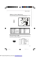
Page 29: ...connector JTPM1 optional This connector connects to a TPM Trusted Platform Module module optional Please refer to the TPM security platform manual for more details and usages Pin Signal Description P...

Page 30: ...Hard disk LED pull up 2 FPPWR SLP MSG LED pull up 3 HD_LED Hard disk active LED 4 FPPWR SLP MSG LED pull up 5 RST_SW Reset Switch low reference pull down to GND 6 PWR_SW PowerSwitchhigh reference pull...

Page 31: ...MIC_R Microphone Right channel 4 PRESENCE Activelow signal signalsBIOSthataHighDefinitionAudiodongle is connected to the analog header PRESENCE 0 when a High Definition Audio dongle is connected 5 LIN...

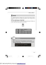
Page 32: ...on use the button to clear data Press the button to clear the data CLR_CMOS1 Buttons Important Make sure that you power off the system before clearing CMOS data Power Button POWER1 This power button i...

Page 33: ...2 OFF Increase 10 speed of FSB 1 OFF 2 ON Increase 15 speed of FSB 1 OFF 2 OFF Increase 20 speed of FSB Important 1 Make sure that you power off the system before setting the switch 2 When overclocki...

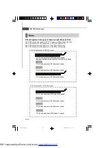
Page 34: ...to PCI Express x16 speed When dual graphic cards enabled it will turn to x8 speed PCI_E4 supports up to PCI Express x8 speed PCI_E2 supports up to PCI Express x1 speed PCI_E3 supports up to PCI Expre...

Page 35: ...h two cards installed an CrossFireXTM Video Link cable is required to connect the golden fingers on the top of these two graphics cards refer to the picture below Please note that although you have in...

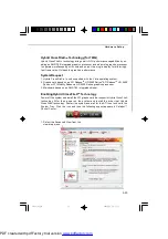
Page 36: ...manual from the manufacturer 3 When all of the hardware and software has been properly set up and installed reboot the system After entering the O S click the Catalyst Control Center icon on the deskt...

Page 37: ...TM HD 2400 Series2 ATI RadeonTM HD 3400 Series or ATI Mobility RadeonTM HD 3400 Series graphics processor 3 Mainboard based on an AMD 780 integrated chipset Enabling Hybrid CrossFireXTM Technology Pow...

Page 38: ...d by Hybrid CrossFireX More details please refer to http game amd com us en crossfirex_hybrid aspx Important Changing integrated graphic memory operating mode may cause Hybrid CrossFire fail To avoid...

Page 39: ...eripheral Component Interconnect Slot The PCI slot supports LAN cards SCSI cards USB cards and other add on cards that comply with PCI specifications At 32 bits and 33 MHz it yields a throughput rate...

Page 40: ...system for optimum use You may need to run the Setup program when An error message appears on the screen during the system booting up and requests you to run SETUP You want to change the default sett...

Page 41: ...digit refers to the chipset as I Intel N nVidia A ATi and V VIA 7th 8th digit refers to the customer as MS all standard customers V1 0 refers to the BIOS version 010109 refers to the date this BIOS wa...

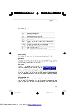
Page 42: ...ter values and move from field to field within a sub menu If you want to return to the main menu just press the Esc General Help F1 The BIOS setup program provides a General Help screen You can call u...

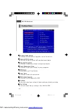
Page 43: ...Use this menu to specify your settings for power management H W Monitor This entry shows your PC health status Green Power Use this menu to specify the power phase BIOS Setting Password Use this menu...

Page 44: ...d Defaults Use this menu to load the default values set by the mainboard manufacturer specifi cally for optimal performance of the mainboard Save Exit Setup Save changes to CMOS and exit setup Exit Wi...

Page 45: ...h from Jan through Dec date The date from 1 to 31 can be keyed by numeric function keys year The year can be adjusted by users Time HH MM SS This allows you to set the system time that you want usuall...

Page 46: ...e Hard Disk S M A R T This allows you to activate the S M A R T Self Monitoring Analysis Reporting Technology capability for the hard disks S M A R T is a utility that monitors your disk status to pre...

Page 47: ...se items show the CPU information BIOS version and memory status of your system read only System Information Press Enter to enter the sub menu and the following screen appears 7576v1 0 3_ami p65 2009...

Page 48: ...s are Enabled Shows a still image logo on the full screen at boot Disabled Shows the POST messages at boot Quick Booting Setting the item to Enabled allows the system to boot within 10 seconds since i...

Page 49: ...ndwidth For better PCI performance you should set the item to higher values CPU Feature Press Enter to enter the sub menu and the following screen appears SVM Support This item allows you to enable di...

Page 50: ...ry for onbaord VGA VGA Share Memory The system shares memory to the onboard VGA card This setting controls the exact memory size shared to the VGA card UMA Location This function is used to select the...

Page 51: ...N controller LAN Option ROM This item is used to decide whether to invoke the Boot ROM of the onboard LAN Onboard IEEE1394 Controller This item allows you to enable disable the onboard IEEE1394 contro...

Page 52: ...sers to enable or disable the SATA controller RAID Mode This item is used to select mode for SATA connectors I O Devices Configuration Press Enter to enter the sub menu and the following screen appear...

Page 53: ...eep mode is a low power state In this state no system context is lost CPU or chipset and hardware main tains all system context S3 STR The S3 sleep mode is a lower power state where the in formation o...

Page 54: ...By Setting to BIOS activates the following fields and use the following fields to set the wake up events Setting to OS the wake up events will be defined by OS Resume From S3 By USB Device The item a...

Page 55: ...to be awakened from the power saving modes through any event on PCIE device Resume by RTC Alarm The field is used to enable or disable the feature of booting up the system on a scheduled time date 75...

Page 56: ...it with in a specific range You can select a fan target value here If the current CPU fan temperature reaches to the target value the smart fan function will be activated It provides several sections...

Page 57: ...l auto adjust the CPU power phase according to the loading of CPU to reach the best power saving function LED Power Control This item allows you to enable disable the CPU Power Phase LED 7576v1 0 3_am...

Page 58: ...e selection and not enter a password To clear a set password just press Enter when you are prompted to enter the password A message will show up confirming the password will be disabled Once the passw...

Page 59: ...rrent CPU DRAM Frequency These items show the current clocks of CPU and Memory speed Read only AMD Cool n Quiet The Cool n Quiet technology can effectively and dynamically lower CPU speed and power co...

Page 60: ...ock frequency in MHz Adjust CPU Ratio This item is used to adjust CPU clock multiplier ratio It is available only when the processor supports this function Adjust CPU NB Ratio This item is used to adj...

Page 61: ...memory It allows system to access multiple banks simultaneously Power Down Enable This is a memory power saving technology When the system does not access memory over a period of time it will automati...

Page 62: ...ld allows you to select the PCIE frequency in MHz Auto Disable DIMM PCI Frequency When set to Enabled the system will remove turn off clocks from empty DRAM PCI slots to minimize the electromagnetic i...

Page 63: ...o chapter 2 for more information about how to clear CMOS data Two ways to save your system from failed overclocking Reboot 1 Press the Power button to reboot the system three times Please note that to...

Page 64: ...by yourself to CMOS Load Settings 1 2 3 4 These items are available after you save your settings in Save Settings 1 2 3 4 items and are used to load the settings from CMOS User Settings 7576v1 0 3_ami...

Page 65: ...set by the BIOS vendor for stable system performance When you select Load Fail Safe Defaults a message as below appears Selecting Ok and pressing Enter loads the BIOS default values for the most stab...

Page 66: ...that simul taneously supports 7 1 sound playback and 2 channels multiple streaming of independent stereo sound out put through the Front Out Left and Front Out Right channels 7576v1 0 A_Realtek Audio...

Page 67: ...s XP environment and could look slightly different if you install the drivers in different operating systems 1 Insert the MSI DVD into the DVD ROM drive The setup screen will automati cally appear 2 C...

Page 68: ...t to install the Realtek High Definition Audio Driver Select this option 4 Click Finish to restart the system Click here 7576v1 0 A_Realtek Audio p65 2009 2 11 11 28 3 PDF created with pdfFactory tria...

Page 69: ...system tray at the lower right corner of the screen to activate the HD Audio Configuration It is also available to enable the audio driver by clicking the Realtek HD Audio Manager from the Control Pa...

Page 70: ...lizer will adjust automatically If you like you may also load an equalizer setting or make an new equalizer setting to save as an new one by using the Load EQ Setting and Save Preset button click Rese...

Page 71: ...like to use preload settings simply click this the whole list will be shown for your selection Delete To delete the pre saved settings which are created from previous steps Equalizer Selection Equaliz...

Page 72: ...w in Others you will find more optimized settings available to you Karaoke Mode Karaoke mode brings Karaoke fun back home Simply using the music you usually play Karaoke mode can help you eliminate th...

Page 73: ...front panel This feature is very helpful when 2 people are using the same computer together for different purposes Click the button and the Mixer ToolBox menu will appear Then check the Enable playbac...

Page 74: ...u must to select the Realtek HD Audio front output from the scroll list first and use a different program to play the second audio source for example use Winamp to play MP3 files You will find that th...

Page 75: ...ute sound output Tool Show the following volume controls This is to let you freely decide which volume control items to be displayed Advanced controls Enable playback multi streaming With this functio...

Page 76: ...ntrols This is to let you freely decide which volume control items to be displayed Enable recording multi streaming Tool Mute Important Realtek Audio allows you to record the CD Line Mic and Stereo Mi...

Page 77: ...Speaker Output Speaker Configuration 1 Plug the speakers in the corresponding jack 2 Dialogue connected device will pop up for your selection Please select the device you have plugged in If the devic...

Page 78: ...led AC 97 jacks If so please check this item to disable front panel jack detection Mute rear panel output when front headphone plugged in Enable auto popup dialogue when device has been plugged in Onc...

Page 79: ...the signal from degrading when it is converted to analog Output Sampling Rate 44 1KHz This is recommend while playing CD 48KHz This is recommended while playing DVD or Dolby 96KHz This is recommended...

Page 80: ...nd then check whether the cable is inserted firmly to the connector or replace the bad speakers with good ones Or you may click the auto test button to test the sounds of each speaker automatically Su...

Page 81: ...sound For example you might have chance to use VOIP function through Internet with your friends The voice of your friend will come out from speakers playback However the voice of your friend might als...

Page 82: ...positional audio before playing 3D audio applica tions like gaming You may also select different environment to choose the most suitable environment you like 7576v1 0 A_Realtek Audio p65 2009 2 11 11...

Page 83: ...language of this utility by choosing from the Language list Also there is a selection Show icon in system tray Switch it on and an icon will show in the system tray Right click on the icon and the Aud...

Page 84: ...eakers to the correct phone jacks in accordance with the setting in software utility n 2 Channel Mode for Stereo Speaker Output 1 Line In 2 Line Out Front channels 3 MIC 4 No function 5 No function 6...

Page 85: ...r Output 4 Channel Analog Audio Output 1 Line In 2 Line Out Front channels 3 MIC 4 Line Out Rear channels 5 No function 6 No function 3 1 2 6 4 5 7576v1 0 A_Realtek Audio p65 2009 2 11 11 28 20 PDF cr...

Page 86: ...el Analog Audio Output 1 Line In 2 Line Out Front channels 3 MIC 4 Line Out Rear channels 5 Line Out Center and Subwoofer channel 6 No function 1 2 6 4 5 3 7576v1 0 A_Realtek Audio p65 2009 2 11 11 28...

Page 87: ...Line Out Center and Subwoofer channel 6 Line Out Side channels 1 2 6 4 5 3 Important To enable 7 1 channel audio out function on Vista operating system you have to install the Realtek Audio Driver Or...

Page 88: ...rboard in windows such as CPU clock voltage fan speed and temperature Before you install the Overclocking Center please make sure the system has meet the following requirements 1 256MB system memory 2...

Page 89: ...cking Center it will have a short cut icon on the desktop and a short cut path in your Start up menu You may double click on each icon to activate Overclocking Center short cut icon on the desktop sho...

Page 90: ...d the information of motherboard memory PCI Motherboard Click Motherboard to read the information of motherboard BIOS installed CPU and installed graphics card 7576v1 0 B_Overclocking Center p65 2009...

Page 91: ...f each memory DIMM slot You can select a DIMM slot you want to read from the SPD list PCI Click PCI to read the information of devices on the motherboard 7576v1 0 B_Overclocking Center p65 2009 2 11 1...

Page 92: ...to enter the DOT screen In DOT you can select the basic setting to reach optimal performance in Novice menu or you can adjust advanced values for overclocking in Advance menu Important You may change...

Page 93: ...setting default setting Click the Cooling Silence Default Game Cinema button to enter it s setting menu Please refer to the following descriptions to adjust the values and save them 7576v1 0 B_Overcl...

Page 94: ...n and the drop down menu will appear In the System Warning block you can set the maximum CPU system temperature and the minimum CPU system fan speed by using the scroll bar The system will pop up a wa...

Page 95: ...oad the settings for the system Important Every time you turn off the system the settings will be restored to the factory default If you want to use the saved settings you have to load it after enteri...

Page 96: ...a is not lost if a drive fails as data is simultaneously written to two drives Drives configured for RAID Striping are said to form a RAID 0 set while drives configured for RAID Mirroring are said to...

Page 97: ...w will appear for about few seconds Press Ctrl F to enter FastBuild utility The FastBuild menu screen will appear The Main Menu is used to choose the opera tion to be performed Important Be sure to en...

Page 98: ...ments This window displays the model number capacities and assignment of the drives physically attached to the SATA host adapter 7576v1 0 C_SATARAID p65 2009 2 11 11 28 3 PDF created with pdfFactory t...

Page 99: ...ow the greatest flexibility manually 1 Press 2 on the Main Menu screen to enter the Define LD Menu 2 Press the arrow keys to highlight an logical drive number you want to define and press Enter to sel...

Page 100: ...ce key to change the assignment to Y Then press Ctrl Y to save the configuration 5 A message will show up on the bottom press any key to save the configura tion or press Ctrl Y to allocate the RAID ca...

Page 101: ...below Press ESC key to the main screen 7 Press ESC key to exit the utility a message System is going to REBOOT Are You Sure will display answer Y to exit it and the system will reboot 7576v1 0 C_SATAR...

Page 102: ...lete and press Del or Alt D delete the RAID set 3 On the next screen a message will display to inform you press Ctrl Y to delete the RAID set or other key to abort it Press Ctrl Y to complete the dele...

Page 103: ...he files from the floppy again after the RAID volume is formatted and Windows setup starts copying files For Windows Vista During the operating system installation after selecting the location to inst...

Page 104: ...un and the setup screen will appear 3 Under the Driver tab click on ATI System Driver by your need The ATI System Driver includes RAID Driver 4 The driver will be automatically installed Important You...

Reviews: