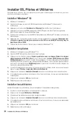
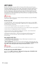
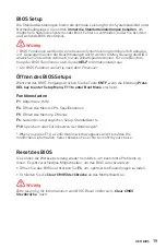
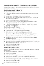
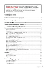
background image

7

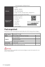
Packungsinhalt

Rückseite E/A

Rückseite E/A

Verbindung/ Aktivität LED
Zustand Bezeichnung

Aus

Keine Verbindung

Gelb

Verbindung

Blinkt

Datenaktivität

Geschwindigkeit LED
Zustand

Bezeichnung

Aus

10 Mbit/s-Verbindung

Grün

100 Mbit/s-Verbindung

Orange

1 GBit/s-Verbindung

LAN Port LED Zustandstabelle

Audio 7.1-Kanal Konfiguration

Um 7.1-Kanal-Audio zu konfigurieren, müssen Sie den Front-Audio-Anschluss mit 

dem JAUD1 Anschluss verbinden und folgen Sie die untenstehenden Schritten.

1. 

Klicken Sie auf 

Realtek HD Audio Manager > Advanced Settings

, um das 

Dialogfeld zu öffnen.

2. 

Wählen Sie 

“Mute the rear output device” („die rückseitigen Ausgänge stumm 

schalten“)

 aus, 

wenn ein Front-Kopfhörer eingesteckt wird

.

3. 

Schließen Sie Ihre Lautsprecher an die Ausgangsbuchsen auf der Rückseite und 

am Frontpanel an. Nach dem Anschluss eines Audio-Klinkensteckers erscheint 

ein Dialogfenster und fragt nach einer Bestätigung für das angeschlossene 

Gerät

.

PS/2 Maus

LAN

USB 3.2  

Gen 1 5GBit/s 

(Typ-A)

USB 2.0

PS/2 Tastatur

DVI-D

VGA

COM

Line-In

Line-Out

Mic-In

Summary of Contents for 7C57-002R

Page 1: ...JUSB3 USB 3 2 Gen 1 5Gbps Connector 14 CPU_FAN1 SYS_FAN1 Fan Connectors 15 JLPT1 Parallel Port Connector 15 JTPM1 TPM Module Connector 16 JCI1 Chassis Intrusion Connector 16 JCOM1 Serial Port Connect...

Page 2: ...e computer before installation is completed This could cause permanent damage to the components as well as injury to the user If you need help during any installation step please consult a certified c...

Page 3: ...rchitecture Supports non ECC UDIMM memory Supports ECC UDIMM memory non ECC mode Supports un buffered memory Please refer www msi com for more information on compatible memory Expansion Slots 1x PCIe...

Page 4: ...he internal USB 3 2 Gen 1 5Gbps connector 6x USB 2 0 ports 2 Type A ports on the back panel 4 ports through the internal USB 2 0 connectors AMD Processor 4x USB 3 2 Gen 1 5Gbps Type A ports on the bac...

Page 5: ...ctor 1x Front panel audio connector 2x System panel connectors 1x Chassis Intrusion connector 1x Serial port connector 1x Parallel port connector 1x TPM module connector 1x Clear CMOS jumper LED Featu...

Page 6: ...per Charger Please refer to http download msi com manual mb DRAGONCENTER2 pdf for more details Package contents Please check the contents of your motherboard package It should contain Motherboard A520...

Page 7: ...to connect front audio I O module to JAUD1 connector and follow the below steps 1 Click on the Realtek HD Audio Manager Advanced Settings to open the dialog below 2 Select Mute the rear output device...

Page 8: ...onents Overview of Components JFP1 JCOM1 JUSB1 JUSB3 JUSB2 JFP2 M2_1 JBAT1 JTPM1 SATA1 SATA2 PCI1 JAUD1 PCI_E3 PCI_E2 PCI_E1 CPU Socket CPU_PWR1 CPU_FAN1 SYS_FAN1 JCI1 JLPT1 ATX_PWR1 EZ Debug LED DIMM...

Page 9: ...heatsink is necessary to prevent overheating and maintain system stability Confirm that the CPU heatsink has formed a tight seal with the CPU before booting your system Overheating can seriously dama...

Page 10: ...y operate lower than the marked value under the default state Please refer www msi com for more information on compatible memory Important When adding or removing expansion cards always turn off the p...

Page 11: ...1 2 10 9 Power LED HDD LED Reset Switch Reserved Power Switch 1 HDD LED 2 Power LED 3 HDD LED 4 Power LED 5 Reset Switch 6 Power Switch 7 Reset Switch 8 Power Switch 9 Reserved 10 No Pin JFP2 1 Speak...

Page 12: ...6Gb s interface ports Each connector can connect to one SATA device SATA4 SATA1 SATA3 SATA2 Important Please do not fold the SATA cable at a 90 degree angle Data loss may result during transmission o...

Page 13: ...3V 13 3 3V 2 3 3V 14 12V 3 Ground 15 Ground 4 5V 16 PS ON 5 Ground 17 Ground 6 5V 18 Ground 7 Ground 19 Ground 8 PWR OK 20 Res 9 5VSB 21 5V 10 12V 22 5V 11 12V 23 5V 12 3 3V 24 Ground 3 2 1 4 CPU_PWR1...

Page 14: ...18 USB3_RX_DN 9 USB2 0 19 Power 10 NC 20 No Pin Important Note that the Power and Ground pins must be connected correctly to avoid possible damage JUSB1 2 USB 2 0 Connectors These connectors allow yo...

Page 15: ...Mode pin definition 1 Ground 2 12V 3 Sense 4 Speed Control Signal Connector Default fan mode Max current Max power CPU_FAN1 Auto mode 2A 24W SYS_FAN1 DC mode 1A 12W 1 DC Mode pin definition 1 Ground...

Page 16: ...3 Go to BIOS Security Chassis Intrusion Configuration 4 Set Chassis Intrusion to Enabled 5 Press F10 to save and exit and then press the Enter key to select Yes 6 Once the chassis cover is opened aga...

Page 17: ...o clear the system configuration set the jumpers to clear the CMOS memory Keep Data default Clear CMOS Reset BIOS Resetting BIOS to default values 1 Power off the computer and unplug the power cord 2...

Page 18: ...also eliminates the time to switch to CSM mode during POST Supports for hard drive partitions larger than 2 TB Supports more than 4 primary partitions with a GUID Partition Table GPT Supports unlimite...

Page 19: ...sor Entering BIOS Setup Press Delete key when the Press DEL key to enter Setup Menu F11 to enter Boot Menu message appears on the screen during the boot process Function key F1 General Help list F4 En...

Page 20: ...up notification then select Run DVDSetup exe to open the installer If you turn off the AutoPlay feature from the Windows Control Panel you can still manually execute the DVDSetup exe from the root pa...

Page 21: ...A 6Gb s 12 M2_1 M 2 Key M 12 ATX_PWR1 CPU_PWR1 13 JAUD1 13 JUSB1 2 USB 2 0 14 JUSB3 USB 3 2 Gen 1 5Gbps 14 CPU_FAN1 SYS_FAN1 15 JLPT1 15 JTPM1 TPM 16 JCI1 16 JCOM1 17 JBAT1 CMOS Reset BIOS 17 EZ LED 1...

Page 22: ...2 ESD ESD ESD PSU PSU 60 C 140 F...

Page 23: ...2667 2800 2933 3000 3066 3200 3466 3600 3733 3866 4000 4133 4266 4400 4600 MHz by A XMP OC 1DPC 1R 4600 MHz 1DPC 2R 3866 MHz non ECC UDIMM ECC UDIMM non ECC un buffered http www msi com PCIe 3 0 x16...

Page 24: ...ID RAID 0 RAID 1 RAID 10 SATA USB AMD A520 USB 3 2 Gen 1 5Gbps USB 3 2 Gen 1 5Gbps 2 USB 2 0 6 A 2 USB 2 0 4 AMD USB 3 2 Gen 1 5Gbps A 4 Realtek ALC892 7 1 HD LAN Realtek RTL8111EPV 1Gbps LAN 1 VGA 1...

Page 25: ...USB 3 2 Gen 1 5Gbps 1 USB 3 2 Gen 1 5Gbps 2 USB 2 0 2 USB 2 0 4 4 CPU 1 4 1 1 2 1 1 1 TPM 1 CMOS 1 LED EZ LED 4 I O NUVOTON NCT6687 R CPU MOS PCI E CPU CPU Micro ATX 9 6 in x 8 7 in 24 4 cm x 22 0 cm...

Page 26: ...6 CPU Z MSI True Color http download msi com manual mb DRAGONCENTER2 pdf A520M PRO C DASH SATA 6G 2 1 IO 1 1 1 DVD 1 1...

Page 27: ...I O JAUD1 1 Realtek HD Audio Manager Advanced Settings 2 Mute the rear output device when a front headphone plugged in 3 I O PS 2 LAN USB 3 2 Gen 1 5Gpbs A USB 2 0 PS 2 DVI D VGA COM LED LAN LAN LAN L...

Page 28: ...8 JFP1 JCOM1 JUSB1 JUSB3 JUSB2 JFP2 M2_1 JBAT1 JTPM1 SATA1 SATA2 PCI1 JAUD1 PCI_E3 PCI_E2 PCI_E1 CPU CPU_PWR1 CPU_FAN1 SYS_FAN1 JCI1 JLPT1 ATX_PWR1 EZ LED DIMMA1 DIMMB1 SATA 3 4...

Page 29: ...9 CPU CPU CPU AM4 BIOS CPU CPU CPU CPU CPU CPU CPU CPU CPU 1 3 5 4 6 7 8 2...

Page 30: ...10 DIMM DIMM DIMMA1 DIMM 1 35V AM4 CPU www msi com MSI 1 1 2 3 3 2 PCI_E1 3 PCI1 PCIe PCI PCI_E1 PCIe 3 0 x1 PCH PCI_E2 PCIe 3 0 x16 CPU PCI_E3 PCIe 3 0 x1 PCH PCI1 PCI...

Page 31: ...D 2 Power LED 3 HDD LED 4 Power LED 5 Reset Switch 6 Power Switch 7 Reset Switch 8 Power Switch 9 Reserved 10 No Pin JFP2 1 Speaker Buzzer 1 Speaker 2 Buzzer 3 Buzzer 4 Speaker HDD LED RESET SW HDD LE...

Page 32: ...12 30 30 M2_1 M 2 Key M M 2 SSD M 2 SATA1 4 SATA 6Gb s SATA 6Gb s SATA SATA4 SATA1 SATA3 SATA2 SATA 90 SATA 1 2 3...

Page 33: ...ound 6 5V 18 Ground 7 Ground 19 Ground 8 PWR OK 20 Res 9 5VSB 21 5V 10 12V 22 5V 11 12V 23 5V 12 3 3V 24 Ground 3 2 1 4 CPU_PWR1 1 Ground 5 12V 2 Ground 6 12V 3 Ground 7 12V 4 Ground 8 12V JAUD1 1 2 1...

Page 34: ..._DP 13 Ground 4 Ground 14 USB3_TX_C_DP 5 USB3_TX_C_DN 15 USB3_TX_C_DN 6 USB3_TX_C_DP 16 Ground 7 Ground 17 USB3_RX_DP 8 USB2 0 18 USB3_RX_DN 9 USB2 0 19 Power 10 NC 20 No Pin JUSB1 2 USB 2 0 USB 2 0 V...

Page 35: ...gnal CPU_FAN1 2A 24W SYS_FAN1 DC 1A 12W 1 DC 1 Ground 2 Voltage Control 3 Sense 4 NC 1 2 26 25 1 RSTB 2 AFD 3 PRND0 4 ERR 5 PRND1 6 PINIT 7 PRND2 8 LPT_SLIN 9 PRND3 10 Ground 11 PRND4 12 Ground 13 PRN...

Page 36: ...usion Enabled 5 F10 Enter Yes 6 1 BIOS Security Chassis Intrusion Configuration 2 Chassis Intrusion Reset 3 F10 Enter Yes 1 2 12 11 1 SPI Power 2 SPI Chip Select 3 Master In Slave Out SPI Data 4 Maste...

Page 37: ...17 JCOM1 1 2 10 9 1 DCD 2 SIN 3 SOUT 4 DTR 5 Ground 6 DSR 7 RTS 8 CTS 9 RI 10 No Pin JBAT1 CMOS Reset BIOS CMOS CMOS CMOS BIOS BIOS 1 2 JBAT1 5 10 3 JBAT1 4 EZ LED LED CPU CPU DRAM DRAM VGA GPU BOOT...

Page 38: ...ace UEFI BIOS BIOS MSI UEFI BIOS UEFI CSM Compatibility Support Module UEFI BIOS UEFI BIOS UEFI UEFI BIOS POST CSM 2TB GUID GPT 4 UEFI UEFI 32 Windows 64 Windows 10 GOP Graphics Output protocol GOP UE...

Page 39: ...19 UEFI BIOS BIOS BIOS BIOS BIOS BIOS HELP BIOS BIOS DEL F11 Delete F1 F4 CPU F5 Memory Z Z F6 F10 F10 Yes No BIOS BIOS BIOS BIOS F6 CMOS BIOS CMOS...

Page 40: ...T Power On Self Test F11 5 Windows 10 USB 6 Press any key to boot from CD or DVD 7 Windows 10 1 Windows 10 2 MSI 3 Select to choose what happens with this disc Run DVDSetup exe MSI DVDSetup exe 4 Driv...

Page 41: ...teur USB 3 2 Gen 1 5Gb s 14 CPU_FAN1 SYS_FAN1 Connecteurs pour ventilateurs 15 JLPT1 Connecteur de port parall le 15 JTPM1 Connecteur de module TPM 16 JCI1 Connecteur intrusion ch ssis 16 JCOM1 Connec...

Page 42: ...nt bien fix s sur la carte m re ou ailleurs dans le bo tier de l ordinateur Ne d marrez pas l ordinateur avant d avoir termin l installation Ceci peut endommager les composants ou vous blesser Si vous...

Page 43: ...e non ECC UDIMM Support m moire ECC UDIMM mode non ECC Support m moire un buffered Veuillez vous r f rer au site www msi com pour plus d informations sur la m moire compatible Slots d extension 1 x sl...

Page 44: ...nnecteur USB 3 2 Gen 1 5Gb s interne 6 x ports USB 2 0 2 ports Type A sur le panneau arri re 4 ports par l interm diaire des connecteurs USB 2 0 internes Processeur AMD 4 x ports USB 3 2 Gen 1 5Gb s T...

Page 45: ...onnecteur audio avant 2 x connecteurs de panneau syst me 1 x connecteur intrusion ch ssis 1 x connecteur de port s rie 1 x connecteur de port parall le 1 x connecteur de module TPM 1 x cavalier Clear...

Page 46: ...download msi com manual mb DRAGONCENTER2 pdf pour plus de d tails Contenu V rifiez tous les articles dans le carton d emballage de votre carte m re L emballage doit contenir Carte m re A520M PRO C DA...

Page 47: ...eur JAUD1 et suivez les tapes ci dessous 1 Cliquez sur Realtek HD Audio Manager Advanced Settings Param tres avanc s pour ouvrir le dialogue suivant 2 Choisissez Mute the rear output device when a fro...

Page 48: ...ts Vue d ensemble des composants JFP1 JCOM1 JUSB1 JUSB3 JUSB2 JFP2 M2_1 JBAT1 JTPM1 SATA1 SATA2 PCI1 JAUD1 PCI_E3 PCI_E2 PCI_E1 Socket processeur CPU_PWR1 CPU_FAN1 SYS_FAN1 JCI1 JLPT1 ATX_PWR1 EZ Debu...

Page 49: ...eur est n cessaire pour prot ger le proces seur contre la surchauffe et maintenir la stabilit du syst me Assurez vous de l tanch it entre le ventilateur et le processeur avant de d mar rer votre syst...

Page 50: ...ules de m moire peuvent fonctionner une fr quence r duite par rapport la valeur indiqu e en mode d faut Veuillez vous r f rer au site www msi com pour plus d informations sur la m moire compatible Imp...

Page 51: ...anneau avant 1 2 10 9 Power LED HDD LED Reset Switch Reserved Power Switch 1 HDD LED 2 Power LED 3 HDD LED 4 Power LED 5 Reset Switch 6 Power Switch 7 Reset Switch 8 Power Switch 9 Reserved 10 No Pin...

Page 52: ...e interface SATA 6Gb s Chaque connecteur peut tre reli un appareil SATA SATA4 SATA1 SATA3 SATA2 Important Veuillez ne pas plier les c bles SATA 90 car cela pourrait entra ner une perte de donn es pend...

Page 53: ...24 13 1 12 ATX_PWR1 1 3 3V 13 3 3V 2 3 3V 14 12V 3 Ground 15 Ground 4 5V 16 PS ON 5 Ground 17 Ground 6 5V 18 Ground 7 Ground 19 Ground 8 PWR OK 20 Res 9 5VSB 21 5V 10 12V 22 5V 11 12V 23 5V 12 3 3V 24...

Page 54: ...C 20 No Pin Important Notez que les c bles d alimentation et de terre doivent tre branch s correctement afin d viter d endommager la carte JUSB1 2 Connecteurs USB 2 0 Ces connecteurs vous permettent d...

Page 55: ...ns le BIOS Advanced Hardware Monitor 1 D finition des broches en mode PWM 1 Ground 2 12V 3 Sense 4 Speed Control Signal Connecteur Mode ventilateur par d faut Courant Max Alimentation Max CPU_FAN1 mod...

Page 56: ...ion ch ssis 4 R glez Chassis Intrusion intrusion ch ssis sur Enabled Activ 5 Appuyez sur F10 pour sauvegarder et quitter Ensuite appuyez sur la touche Enter Entr e pour choisir Yes Oui 6 D sormais si...

Page 57: ...e CMOS R initialiser le BIOS R initialiser le BIOS aux valeurs par d faut 1 Eteignez l ordinateur et d branchez le c ble d alimentation de la prise lectrique 2 Utilisez un couvercle de cavalier pour f...

Page 58: ...otest du BIOS Il limine galement le temps attendre pour passer en mode CSM pendant le POST Prend en charge des partitions de disque dur sup rieures 2 To Prend en charge plus de 4 partitions principale...

Page 59: ...t le message Press DEL key to enter Setup Menu F11 to enter Boot Menu sur l cran veuillez appuyer sur la touche Suppr Touches de fonction F1 Liste d aide g n rale F4 Entrer dans le menu de r glages d...

Page 60: ...at happens with this disc puis choisissez Lancer DVDSetup exe Run DVDSetup exe pour ouvrir l outil d installation Si vous d sactivez la fonction AutoPlay dans le panneau de configuration Windows vous...

Page 61: ...1 5GBit s Anschluss 14 CPU_FAN1 SYS_FAN1 Stromanschl sse f r L fter 15 JLPT1 Parallele Schnittstelle 15 JTPM1 TPM Anschluss 16 JCI1 Geh usekontaktanschluss 16 JCOM1 Serieller Anschluss 17 JBAT1 Clear...

Page 62: ...uter nicht bevor die Installation abgeschlossen ist Dies k nnte permanente Sch den an den Komponenten sowie zu das Verletzung des Benutzers verursachen Sollten Sie Hilfe bei der Installation ben tigen...

Page 63: ...eicher Unterst tzt ECC UDIMM Speicher non ECC Modus Unterst tzt ungepufferte Speicher Weitere Informationen zu kompatiblen Speicher finden Sie unter http www msi com Erweiterung anschl sse 1x PCIe 3 0...

Page 64: ...gung 6x USB 2 0 Anschl sse 2 Typ A Anschl sse an der r ckseitigen Anschlussleiste 4 stehen durch die internen USB 2 0 Anschl sse zur Verf gung AMD Prozessor 4x USB 3 2 Gen 1 5GBit s Typ A Anschl sse...

Page 65: ...er Anschluss 1x Audioanschluss des Frontpanels 2x System Panel Anschl sse 1x Geh usekontaktschalter 1x Serieller Anschluss 1x Parallele Schnittstelle 1x TPM Anschluss 1x Clear CMOS Steckbr cke LED Fun...

Page 66: ...formationen finden Sie unter http download msi com manual mb DRAGONCENTER2 pdf Packungsinhalt berpr fen Sie den Packungsinhalt des Mainboards Die Packung sollte enthalten Motherboard A520M PRO C DASH...

Page 67: ...s verbinden und folgen Sie die untenstehenden Schritten 1 Klicken Sie auf Realtek HD Audio Manager Advanced Settings um das Dialogfeld zu ffnen 2 W hlen Sie Mute the rear output device die r ckseitige...

Page 68: ...nenten bersicht der Komponenten JFP1 JCOM1 JUSB1 JUSB3 JUSB2 JFP2 M2_1 JBAT1 JTPM1 SATA1 SATA2 PCI1 JAUD1 PCI_E3 PCI_E2 PCI_E1 CPU Sockel CPU_PWR1 CPU_FAN1 SYS_FAN1 JCI1 JLPT1 ATX_PWR1 EZ Debug LED DI...

Page 69: ...itzung zu vermeiden und die Systemstabilit t beizubehalten Stellen Sie sicher dass Ihr K hlk rper eine feste Verbindung mit der CPU herg estellt hat bevor Sie Ihr System starten berhitzung besch digt...

Page 70: ...einer niedrigeren Frequenz unter dem Standardzustand arbeiten Weitere Informationen zu kompatiblen Speichermodulen finden Sie unter http www msi com Wichtig Achten Sie darauf dass Sie den Strom absch...

Page 71: ...els 1 2 10 9 Power LED HDD LED Reset Switch Reserved Power Switch 1 HDD LED 2 Power LED 3 HDD LED 4 Power LED 5 Reset Switch 6 Power Switch 7 Reset Switch 8 Power Switch 9 Reserved 10 No Pin JFP2 1 Sp...

Page 72: ...Diese Anschl sse basieren auf der Hochgeschwindigkeitsschnittstelle SATA 6Gb s Pro Anschluss kann ein SATA Ger t angeschlossen werden SATA4 SATA1 SATA3 SATA2 Wichtig Knicken Sie das SATA Kabel nicht...

Page 73: ...3 3V 13 3 3V 2 3 3V 14 12V 3 Ground 15 Ground 4 5V 16 PS ON 5 Ground 17 Ground 6 5V 18 Ground 7 Ground 19 Ground 8 PWR OK 20 Res 9 5VSB 21 5V 10 12V 22 5V 11 12V 23 5V 12 3 3V 24 Ground 3 2 1 4 CPU_PW...

Page 74: ...ie dass Sie die mit Stromf hrende Leitung und Erdleitung bezeichneten Pins korrekt verbinden m ssen ansonsten kann es zu Sch den kommen JUSB1 2 USB 2 0 Anschl sse Mit diesen Anschl sse k nnen Sie die...

Page 75: ...l ndern 1 Pin Belegung des PWM Modus 1 Ground 2 12V 3 Sense 4 Speed Control Signal Anschluss Standard l ftermodus Max Strom Max Leistung CPU_FAN1 Auto mode 2A 24W SYS_FAN1 DC mode 1A 12W 1 Pin Belegun...

Page 76: ...urity Chassis Intrusion Configuration 4 Stellen Sie Chassis Intrusion auf Enabled 5 Dr cken Sie F10 zum Speichern und Beenden und dr cken Sie dann die Enter Taste um Ja auszuw hlen 6 Bei eingeschaltet...

Page 77: ...m ssen Sie die Steckbr cke f r kurze Zeit umsetzen Daten beibehalten Standardwert CMOS Daten l schen Reset des BIOS R cksetzen des BIOS auf Standardwerte 1 Schalten Sie den Computer ab und ziehen Sie...

Page 78: ...nd des POST in den CSM Modus zu wechseln Unterst tzt Festplattenpartitionen die gr er als 2 TB sind Unterst tzt mehr als 4 prim re Partitionen mit einer GUID Partitionstabelle GPT Unterst tzt eine unb...

Page 79: ...s W hrend des BOOT Vorgangs dr cken Sie die Taste ENTF wenn die Meldung Press DEL key to enter Setup Menu F11 to enter Boot Menu erscheint Funktionstasten F1 Allgemeine Hilfe F4 ffnen des Men s CPU Sp...

Page 80: ...ldatentr ger aus und w hlen Sie DVDSetup exe starten aus um den Installer zu ffnen Wenn Sie die AutoPlay Funktionen in der Windows Systemsteuerung ausschalten k nnen Sie das Programm DVD Setup exe im...

Page 81: ...A1 4 SATA 6 12 M2_1 M 2 M 12 ATX_PWR1 CPU_PWR1 13 JAUD1 13 JUSB1 2 USB 2 0 14 JUSB3 USB 3 2 Gen 1 5 14 CPU_FAN1 SYS_FAN1 15 JLPT1 15 JTPM1 16 JCI1 16 JCOM1 17 JBAT1 CMOS BIOS 17 EZ 17 UEFI BIOS 18 BIO...

Page 82: ...2 60 C 140 F...

Page 83: ...JEDEC DDR4 2667 2800 2933 3000 3066 3200 3466 3600 3733 3866 4000 4133 4266 4400 4600 A XMP OC MODE 1DPC 1R 4600 1DPC 2R 3866 non ECC UDIMM ECC UDIMM non ECC www msi com 1x PCIe 3 0 x16 AMD PCI_E2 2x...

Page 84: ...10 SATA USB AMD A520 2x USB 3 2 Gen 1 5 USB 3 2 Gen 1 5 6x USB 2 0 2 Type A 4 USB 2 0 AMD 4x USB 3 2 Gen 1 5 Type A Realtek ALC892 Codec 7 1 High Definition Audio LAN 1x Realtek RTL8111EPV 1x VGA 1x...

Page 85: ...SATA 6 1x M 2 M 1x USB 3 2 Gen 1 5 2 USB 3 2 Gen 1 5 2x USB 2 0 4 USB 2 0 1x 4 1x 4 1x 2x 1x 1x 1x 1x TPM 1x CMOS 4x EZ NUVOTON NCT6687 R MOS PCI E Micro ATX 9 6 x 8 7 24 4 x 22 0 BIOS 1x 256 UEFI AM...

Page 86: ...ogle Toolbar Google Drive Norton Internet Security Solution Dragon Center User Scenario Hardware Monitor True Color Live Update Speed Up Smart Tool Super Charger http download msi com manual mb DRAGON...

Page 87: ...10 100 1 LAN Audio 7 1 7 1 JAUD1 1 Realtek HD Audio Manager Advanced Settings 2 Mute the rear output device when a front headphone plugged in 3 PS 2 LAN USB 3 2 Gen 1 5 Type A USB 2 0 PS 2 DVI D VGA C...

Page 88: ...8 JFP1 JCOM1 JUSB1 JUSB3 JUSB2 JFP2 M2_1 JBAT1 JTPM1 SATA1 SATA2 PCI1 JAUD1 PCI_E3 PCI_E2 PCI_E1 CPU_PWR1 CPU_FAN1 SYS_FAN1 JCI1 JLPT1 ATX_PWR1 EZ DIMMA1 DIMMB1 SATA 3 4...

Page 89: ...9 4 BIOS 1 3 5 4 6 7 8 2...

Page 90: ...10 DIMM DIMM DIMMA1 DIMM 1 35 4 www msi com MSI Gaming Series Graphics Card Bolster 1 1 2 3 3 2 PCI_E1 3 PCI1 PCIe PCI PCI_E1 PCIe 3 0 x1 PCH PCI_E2 PCIe 3 0 x16 CPU PCI_E3 PCIe 3 0 x1 PCH PCI1 PCI...

Page 91: ...witch 1 HDD LED 2 Power LED 3 HDD LED 4 Power LED 5 Reset Switch 6 Power Switch 7 Reset Switch 8 Power Switch 9 Reserved 10 No Pin JFP2 1 Speaker Buzzer 1 Speaker 2 Buzzer 3 Buzzer 4 Speaker HDD LED R...

Page 92: ...12 30 30 M2_1 M 2 M M 2 SSD M 2 SATA1 4 SATA 6 SATA 6 SATA SATA4 SATA1 SATA3 SATA2 SATA SATA 1 2 3...

Page 93: ...nd 6 5V 18 Ground 7 Ground 19 Ground 8 PWR OK 20 Res 9 5VSB 21 5V 10 12V 22 5V 11 12V 23 5V 12 3 3V 24 Ground 3 2 1 4 CPU_PWR1 1 Ground 5 12V 2 Ground 6 12V 3 Ground 7 12V 4 Ground 8 12V JAUD1 1 2 10...

Page 94: ...nd 4 Ground 14 USB3_TX_C_DP 5 USB3_TX_C_DN 15 USB3_TX_C_DN 6 USB3_TX_C_DP 16 Ground 7 Ground 17 USB3_RX_DP 8 USB2 0 18 USB3_RX_DN 9 USB2 0 19 Power 10 NC 20 No Pin JUSB1 2 USB 2 0 USB 2 0 VCC iPad iPh...

Page 95: ...nal CPU_FAN1 2 24 SYS_FAN1 DC 1 12 1 DC 1 Ground 2 Voltage Control 3 Sense 4 NC 1 2 26 25 1 RSTB 2 AFD 3 PRND0 4 ERR 5 PRND1 6 PINIT 7 PRND2 8 LPT_SLIN 9 PRND3 10 Ground 11 PRND4 12 Ground 13 PRND5 14...

Page 96: ...Enabled 5 F10 Enter Yes 6 1 BIOS Security Chassis Intrusion Configuration 2 Chassis Intrusion Reset 3 F10 Enter Yes 1 2 12 11 1 SPI Power 2 SPI Chip Select 3 Master In Slave Out SPI Data 4 Master In S...

Page 97: ...17 JCOM1 1 2 10 9 1 DCD 2 SIN 3 SOUT 4 DTR 5 Ground 6 DSR 7 RTS 8 CTS 9 RI 10 No Pin JBAT1 CMOS BIOS CMOS CMOS BIOS BIOS 1 2 JBAT1 5 10 3 JBAT1 4 EZ CPU DRAM DRAM VGA BOOT...

Page 98: ...S UEFI BIOS MSI UEFI BIOS UEFI BIOS CSM UEFI BIOS UEFI BIOS UEFI UEFI BIOS CSM POST 2 4 GUID GPT UEFI UEFI 32 Windows 64 Windows 10 There is no GOP Graphics Output protocol support detected in this gr...

Page 99: ...19 UEFI BIOS BIOS BIOS BIOS BIOS BIOS HELP BIOS BIOS Delete Press DEL key to enter Setup Menu F11 to enter Boot Menu F1 F4 F5 Memory Z F6 F10 F10 Yes No BIOS BIOS BIOS F6 CMOS BIOS CMOS...

Page 100: ...Power On Self Test 5 USB 6 Press any key to boot from CD or DVD 7 Windows 10 1 Windows 10 2 MSI Driver Disc 3 Select to choose what happens with this disc Run DVDSetup exe Windows DVDSetup exe MSI Dri...

Page 101: ...A1 4 SATA 6Gb s 12 M2_1 M 2 M 12 ATX_PWR1 CPU_PWR1 13 JAUD1 13 JUSB1 2 USB 2 0 14 JUSB3 USB 3 2 Gen 1 5Gbps 14 CPU_FAN1 SYS_FAN1 15 JLPT1 15 JTPM1 TPM 16 JCI1 16 JCOM1 17 JBAT1 CMOS BIOS 17 LED 17 UEF...

Page 102: ...2 ESD ESD ESD 60 140...

Page 103: ...C DDR4 2667 2800 2933 3000 3066 3200 3466 3600 3733 3866 4000 4133 4266 4400 4600 MHz A XMP OC 1DPC 1R 4600 MHz 1DPC 2R 3866 MHz ECC UDIMM ECC UDIMM ECC www msi com 1 PCIe 3 0 x16 AMD PCI_E2 2 PCIe 3...

Page 104: ...RAID 0 RAID 1 RAID 10 USB AMD A520 2 USB 3 2 Gen 1 5Gbps USB 3 2 Gen 1 5Gbps 6 USB 2 0 2 Type A USB 2 0 4 AMD 4 USB 3 2 Gen 1 5Gbps Type A Realtek ALC892 7 1 LAN 1 Realtek RTL8111EPV 1Gbps 1 VGA 1 DVI...

Page 105: ...M 1 USB 3 2 Gen 1 5Gbps 2 USB 3 2 Gen 1 5Gbps 2 USB 2 0 4 USB 2 0 1 4 pin CPU 1 4 pin 1 2 1 1 1 1 TPM 1 CMOS LED 4 LED I O NUVOTON NCT6687 R CPU MOS PCI E CPU CPU Micro ATX 9 6 x 8 7 24 4 x 22 0 BIOS...

Page 106: ...6 DRAGON CENTER MSI GAMING CPU Z Google Google Google Dragon Center True Color Live Update http download msi com manual mb DRAGONCENTER2 pdf A520M PRO C DASH SATA 6G 2 1 IO 1 1 1 DVD 1 1...

Page 107: ...00 Mbps 1 Gbps LAN LED 7 1 7 1 I O JAUD1 1 Realtek HD Audio Manager Advanced Settings 2 Mute the rear output device when a front headphone plugged in 3 I O PS 2 LAN USB 3 2 Gen 1 5Gpbs Type A USB 2 0...

Page 108: ...8 JFP1 JCOM1 JUSB1 JUSB3 JUSB2 JFP2 M2_1 JBAT1 JTPM1 SATA1 SATA2 PCI1 JAUD1 PCI_E3 PCI_E2 PCI_E1 CPU CPU_PWR1 CPU_FAN1 SYS_FAN1 JCI1 JLPT1 ATX_PWR1 EZ Debug LED DIMMA1 DIMMB1 SATA 3 4...

Page 109: ...9 CPU CPU CPU AM4 BIOS CPU CPU CPU CPU CPU CPU CPU CPU CPU CPU 1 3 5 4 6 7 8 2...

Page 110: ...10 DIMM DIMM DIMMA1 1 35V AM4 CPU www msi com MSI 1 1 2 3 3 2 PCI_E1 3 PCI1 PCIe PCI PCI_E1 PCIe 3 0 x1 PCH PCI_E2 PCIe 3 0 x16 CPU PCI_E3 PCIe 3 0 x1 PCH PCI1 PCI...

Page 111: ...Switch 1 HDD LED 2 Power LED 3 HDD LED 4 Power LED 5 Reset Switch 6 Power Switch 7 Reset Switch 8 Power Switch 9 Reserved 10 No Pin JFP2 1 Speaker Buzzer 1 Speaker 2 Buzzer 3 Buzzer 4 Speaker HDD LED...

Page 112: ...12 30 30 M2_1 M 2 M M 2 SSD M 2 SATA1 4 SATA 6Gb s SATA 6Gb s SATA SATA4 SATA1 SATA3 SATA2 SATA 90 SATA 1 2 3...

Page 113: ...ound 6 5V 18 Ground 7 Ground 19 Ground 8 PWR OK 20 Res 9 5VSB 21 5V 10 12V 22 5V 11 12V 23 5V 12 3 3V 24 Ground 3 2 1 4 CPU_PWR1 1 Ground 5 12V 2 Ground 6 12V 3 Ground 7 12V 4 Ground 8 12V JAUD1 1 2 1...

Page 114: ...Ground 4 Ground 14 USB3_TX_C_DP 5 USB3_TX_C_DN 15 USB3_TX_C_DN 6 USB3_TX_C_DP 16 Ground 7 Ground 17 USB3_RX_DP 8 USB2 0 18 USB3_RX_DN 9 USB2 0 19 Power 10 NC 20 No Pin JUSB1 2 USB 2 0 USB 2 0 VCC iPad...

Page 115: ...al CPU_FAN1 2A 24W SYS_FAN1 DC 1A 12W 1 DC 1 Ground 2 Voltage Control 3 Sense 4 NC 1 2 26 25 1 RSTB 2 AFD 3 PRND0 4 ERR 5 PRND1 6 PINIT 7 PRND2 8 LPT_SLIN 9 PRND3 10 Ground 11 PRND4 12 Ground 13 PRND5...

Page 116: ...d 5 F10 Enter Yes 6 1 BIOS Security Chassis Intrusion Configuration 2 Chassis Intrusion Reset 3 F10 Enter Yes 1 2 12 11 1 SPI Power 2 SPI Chip Select 3 Master In Slave Out SPI Data 4 Master In Slave I...

Page 117: ...17 JCOM1 1 2 10 9 1 DCD 2 SIN 3 SOUT 4 DTR 5 Ground 6 DSR 7 RTS 8 CTS 9 RI 10 No Pin JBAT1 CMOS BIOS CMOS CMOS CMOS BIOS BIOS 1 2 JBAT1 5 10 3 JBAT1 4 LED LED CPU CPU DRAM DRAM VGA GPU BOOT...

Page 118: ...UEFI BIOS UEFI CSM UEFI BIOS UEFI BIOS UEFI UEFI BIOS POST CSM 2 TB GUID GPT 4 UEFI UEFI 32 Windows 64 Windows 10 There is no GOP Graphics Output protocol support detected in this graphics card GOP Gr...

Page 119: ...19 UEFI BIOS BIOS BIOS BIOS BIOS BIOS BIOS Press DEL key to enter Setup Menu F11 to enter Boot Menu Delete F1 F4 CPU F5 Memory Z F6 F10 F10 Yes No BIOS BIOS BIOS BIOS F6 CMOS CMOS BIOS...

Page 120: ...F11 5 Windows 10 USB 6 Press any key to boot from CD or DVD 7 Windows 10 1 Windows 10 2 MSI 3 Select to choose what happens with this disc Run DVDSetup exe Windows AutoPlay MSI DVDSetup exe 4 Drivers...

Page 121: ...4 SATA 6Gb s 12 M2_1 M 2 M 12 ATX_PWR1 CPU_PWR1 13 JAUD1 13 JUSB1 2 USB 2 0 14 JUSB3 USB 3 2 Gen 1 5Gbps 14 CPU_FAN1 SYS_FAN1 15 JLPT1 15 JTPM1 TPM 16 JCI1 16 JCOM1 17 JBAT1 CMOS BIOS 17 LED 17 UEFI...

Page 122: ...2 ESD 60 C 140 F...

Page 123: ...C DDR4 2667 2800 2933 3000 3066 3200 3466 3600 3733 3866 4000 4133 4266 4400 4600 MHz A XMP OC MODE 1DPC 1R 4600 MHz 1DPC 2R 3866 MHz non ECC UDIMM ECC UDIMM non ECC www msi com 1 PCIe 3 0 x16 AMD PCI...

Page 124: ...TA RAID 0 RAID 1 RAID 10 USB AMD A520 2 USB 3 2 Gen 1 5Gbps USB 3 2 Gen 1 5Gbps 6 USB 2 0 2 Type A 4 USB 2 0 AMD 4 USB 3 2 Gen 1 5Gbps Type A Realtek ALC892 7 1 1 Realtek RTL8111H 1Gbps 1 VGA 1 DVI D...

Page 125: ...M 1 USB 3 2 Gen1 5Gbps 2 USB 3 2 Gen 1 5Gbps 2 USB 2 0 4 USB 2 0 1 4 pin CPU 1 4 pin 1 2 1 1 1 1 TPM 1 CMOS LED 4 EZ LED I O NUVOTON NCT6687 R CPU MOS PCI E CPU CPU Micro ATX 9 6 x 8 7 24 4 x 22 0 BIO...

Page 126: ...Google Google Norton Internet Security Solution Dragon Center User Scenario Hardware Monitor True Color Live Update Speed Up Smart Tool Super Charger http download msi com manual mb DRAGONCENTER2 pdf...

Page 127: ...7 I O I O 10 Mbps 100 Mbps 1 Gbps LED 7 1 7 1 I O JAUD1 1 Realtek HD Audio Manager Advanced Settings 2 3 I O PS 2 USB 3 2 Gen 1 5Gpbs Type A USB 2 0 PS 2 DVI D VGA COM...

Page 128: ...8 JFP1 JCOM1 JUSB1 JUSB3 JUSB2 JFP2 M2_1 JBAT1 JTPM1 SATA1 SATA2 PCI1 JAUD1 PCI_E3 PCI_E2 PCI_E1 CPU_PWR1 CPU_FAN1 SYS_FAN1 JCI1 JLPT1 ATX_PWR1 EZ LED DIMMA1 DIMMB1 SATA 3 4...

Page 129: ...9 CPU CPU CPU CPU CPU Return Merchandise Authorization RMA CPU CPU CPU CPU CPU CPU 1 3 5 4 6 7 8 2...

Page 130: ...10 DIMM DIMM DIMMA1 1 35V AM4 www msi com MSI Gaming Series 1 1 2 3 3 2 PCI_E1 3 PCI1 PCIe PCI PCI_E1 PCIe 3 0 x1 PCH PCI_E2 PCIe 3 0 x16 CPU PCI_E3 PCIe 3 0 x1 PCH PCI1 PCI...

Page 131: ...Switch 1 HDD LED 2 Power LED 3 HDD LED 4 Power LED 5 Reset Switch 6 Power Switch 7 Reset Switch 8 Power Switch 9 Reserved 10 No Pin JFP2 1 Speaker Buzzer 1 Speaker 2 Buzzer 3 Buzzer 4 Speaker HDD LED...

Page 132: ...12 30 30 M2_1 M 2 M M 2 SSD M 2 SATA1 4 SATA 6Gb s SATA 6Gb s SATA SATA4 SATA1 SATA3 SATA2 SATA 90 SATA 1 2 3...

Page 133: ...ound 6 5V 18 Ground 7 Ground 19 Ground 8 PWR OK 20 Res 9 5VSB 21 5V 10 12V 22 5V 11 12V 23 5V 12 3 3V 24 Ground 3 2 1 4 CPU_PWR1 1 Ground 5 12V 2 Ground 6 12V 3 Ground 7 12V 4 Ground 8 12V JAUD1 1 2 1...

Page 134: ...Ground 4 Ground 14 USB3_TX_C_DP 5 USB3_TX_C_DN 15 USB3_TX_C_DN 6 USB3_TX_C_DP 16 Ground 7 Ground 17 USB3_RX_DP 8 USB2 0 18 USB3_RX_DN 9 USB2 0 19 Power 10 NC 20 No Pin JUSB1 2 USB 2 0 USB 2 0 VCC USB...

Page 135: ...CPU_FAN1 Auto 2A 24W SYS_FAN1 DC 1A 12W 1 DC 1 Ground 2 Voltage Control 3 Sense 4 NC 1 2 26 25 1 RSTB 2 AFD 3 PRND0 4 ERR 5 PRND1 6 PINIT 7 PRND2 8 LPT_SLIN 9 PRND3 10 Ground 11 PRND4 12 Ground 13 PRN...

Page 136: ...d 5 F10 Enter Yes 6 1 BIOS Security Chassis Intrusion Configuration 2 Chassis Intrusion Reset 3 F10 Enter Yes 1 2 12 11 1 SPI Power 2 SPI Chip Select 3 Master In Slave Out SPI Data 4 Master In Slave I...

Page 137: ...17 JCOM1 1 2 10 9 1 DCD 2 SIN 3 SOUT 4 DTR 5 Ground 6 DSR 7 RTS 8 CTS 9 RI 10 No Pin JBAT1 CMOS BIOS CMOS CMOS CMOS BIOS BIOS 1 2 JBAT1 5 10 3 JBAT1 4 LED LED CPU CPU DRAM VGA BOOT...

Page 138: ...EFI BIOS UEFI BIOS UEFI UEFI BIOS POST CSM 2 TB GUID GPT UEFI UEFI 32 bit Windows operating system 64 Windows 10 Older graphics card There is no GOP Graphics Output protocol support detected in this g...

Page 139: ...19 UEFI BIOS BIOS BIOS BIOS BIOS HELP BIOS BIOS BIOS DEL F11 Delete F1 F4 CPU F5 Memory Z F6 F10 F10 BIOS BIOS BIOS BIOS F6 CMOS CMOS BIOS...

Page 140: ...w msi com Windows 10 1 2 Windows 10 USB 3 4 POST F11 5 Windows 10 USB 6 Press any key to boot from CD or DVD 7 Windows 10 1 Windows 10 2 MSI 3 DVDSetup exe Windows MSI DVDSetup exe 4 5 6 7 8 1 2 3 4 5...

Page 141: ...A 6Gb s 12 M2_1 M 2 Key M 12 ATX_PWR1 CPU_PWR1 13 JAUD1 13 JUSB1 2 USB 2 0 14 JUSB3 USB 3 2 Gen 1 5Gbps 14 CPU_FAN1 SYS_FAN1 15 JLPT1 15 JTPM1 TPM 16 JCI1 16 JCOM1 17 JBAT1 CMOS BIOS 17 EZ Debug LED 1...

Page 142: ...2 ESD PC ESD ESD PC PC PC PC PC PC 60OC 140OF...

Page 143: ...OC MODE DDR4 2667 2800 2933 3000 3066 3200 3466 3600 3733 3866 4000 4133 4266 4400 4600 MHz 1DPC 1R 4600 MHz 1DPC 2R 3866 MHz non ECC UDIMM ECC UDIMM non ECC un buffered www msi com PCIe 3 0 x16 x1 A...

Page 144: ...RAID 1 RAID 10 USB AMD A520 USB 3 2 Gen 1 5Gbps 2 USB 3 2 Gen 1 5Gbps USB 2 0 x6 2 Type A USB 2 0 4 AMD 4 USB 3 2 Gen 1 5Gbps Type A Realtek ALC892 7 1 HD LAN Realtek RTL8111EPV 1Gbps LAN x1 VGA x1 D...

Page 145: ...Gen 1 5Gbps x1 2 USB 3 2 Gen 1 5Gbps USB 2 0 x2 4 USB 2 0 4 CPU x1 4 x1 x1 x2 x1 x1 x1 TPM x1 CMOS x1 LED EZ Debug LED x4 I O NUVOTON NCT6687 R CPU MOS PCI E CPU CPU Micro ATX 9 6 in x 8 7 in 24 4 cm...

Page 146: ...Google Toolbar Google Drive Norton Internet Security Solution User Scenario Hardware Monitor True Color Live Update Speed Up Smart Tool Super Charger http download msi com manual mb DRAGONCENTER2 pdf...

Page 147: ...0 Mbps 100 Mbps 1 Gbps LAN LED 7 1 7 1 I O JAUD1 1 Realtek HD Audio Manager Advanced Settings 2 Mute the rear output device when a front headphone plugged in 3 I O PS 2 LAN USB 3 2 Gen 1 5Gpbs Type A...

Page 148: ...8 JFP1 JCOM1 JUSB1 JUSB3 JUSB2 JFP2 M2_1 JBAT1 JTPM1 SATA1 SATA2 PCI1 JAUD1 PCI_E3 PCI_E2 PCI_E1 CPU CPU_PWR1 CPU_FAN1 SYS_FAN1 JCI1 JLPT1 ATX_PWR1 EZ Debug LED DIMMA1 DIMMB1 SATA 3 4...

Page 149: ...9 CPU CPU CPU AM4 BIOS CPU CPU CPU CPU CPU CPU CPU CPU CPU CPU CPU CPU CPU CPU 1 3 5 4 6 7 8 2...

Page 150: ...DIMM DIMM DIMMA1 1 35V DIMM AM4 CPU www msi com MSI Gaming Series Graphics Card Bolster 1 1 2 3 3 2 PCI_E1 3 PCI1 PCIe PCI PCI_E1 PCIe 3 0 x1 PCH PCI_E2 PCIe 3 0 x16 CPU PCI_E3 PCIe 3 0 x1 PCH PCI1 P...

Page 151: ...Switch 1 HDD LED 2 Power LED 3 HDD LED 4 Power LED 5 Reset Switch 6 Power Switch 7 Reset Switch 8 Power Switch 9 Reserved 10 No Pin JFP2 1 Speaker Buzzer 1 Speaker 2 Buzzer 3 Buzzer 4 Speaker HDD LED...

Page 152: ...12 30 30 M2_1 M 2 Key M M 2 SSD M 2 SATA1 4 SATA 6Gb s SATA 6Gb s SATA SATA4 SATA1 SATA3 SATA2 SATA 90 SATA 1 2 3...

Page 153: ...ound 6 5V 18 Ground 7 Ground 19 Ground 8 PWR OK 20 Res 9 5VSB 21 5V 10 12V 22 5V 11 12V 23 5V 12 3 3V 24 Ground 3 2 1 4 CPU_PWR1 1 Ground 5 12V 2 Ground 6 12V 3 Ground 7 12V 4 Ground 8 12V JAUD1 1 2 1...

Page 154: ...Ground 4 Ground 14 USB3_TX_C_DP 5 USB3_TX_C_DN 15 USB3_TX_C_DN 6 USB3_TX_C_DP 16 Ground 7 Ground 17 USB3_RX_DP 8 USB2 0 18 USB3_RX_DN 9 USB2 0 19 Power 10 NC 20 No Pin JUSB1 2 USB 2 0 USB 2 0 VCC USB...

Page 155: ...gnal CPU_FAN1 2A 24W SYS_FAN1 DC 1A 12W 1 DC 1 Ground 2 Voltage Control 3 Sense 4 NC 1 2 26 25 1 RSTB 2 AFD 3 PRND0 4 ERR 5 PRND1 6 PINIT 7 PRND2 8 LPT_SLIN 9 PRND3 10 Ground 11 PRND4 12 Ground 13 PRN...

Page 156: ...usion Enabled 5 F10 Enter Yes 6 1 BIOS Security Chassis Intrusion Configuration 2 Chassis Intrusion Reset 3 F10 Enter Yes 1 2 12 11 1 SPI Power 2 SPI Chip Select 3 Master In Slave Out SPI Data 4 Maste...

Page 157: ...7 JCOM1 1 2 10 9 1 DCD 2 SIN 3 SOUT 4 DTR 5 Ground 6 DSR 7 RTS 8 CTS 9 RI 10 No Pin JBAT1 CMOS BIOS CMOS CMOS CMOS BIOS BIOS 1 PC 2 JBAT1 5 10 3 JBAT1 4 EZ Debug LED LED CPU CPU DRAM DRAM VGA GPU BOOT...

Page 158: ...FI BIOS BIOS MSI UEFI BIOS UEFI CSM Compatibility Support Module UEFI BIOS UEFI BIOS UEFI UEFI BIOS POST CSM 2 TB GUID Partition Table GPT 4 UEFI UEFI 32 Windows 64 Windows 10 GOP Graphics Output Prot...

Page 159: ...IOS BIOS BIOS BIOS BIOS HELP BIOS BIOS Press DEL key to enter Setup Menu F11 to enter Boot Menu Delete F1 F4 CPU F5 Memory Z F6 optimized defaults F10 F10 Yes No BIOS BIOS BIOS BIOS F6 optimized defau...

Page 160: ...dows 10 3 PC Restart 4 POST Power On Self Test F11 5 6 Press any key to boot from CD or DVD Enter 7 Windows 10 1 Windows 10 2 MSI 3 Select to choose what happens with this disc Run DVDSetup exe Window...

Page 161: ...21 OS 1 2 Utilities 3 4 Install 5 6 OK 7 PC...

Page 162: ...harmful interference and 2 this device must accept any interference received including interference that may cause undesired operation CE Conformity Products bearing the CE marking comply with one or...

Page 163: ...lecte MSI WEEE 2002 96 EC 13 2005 MSI MSI EC ESPA OL MSI como empresa comprometida con la protecci n del medio ambiente recomienda Bajo la directiva 2002 96 EC de la Uni n Europea en materia de desech...

Page 164: ...ben hogy k rnyezet nket megv dj k illetve k rnyezetv d k nt fell pve az MSI eml kezteti nt hogy Az Eur pai Uni EU 2005 augusztus 13 n hat lyba l p az elektromos s elektronikus berendez sek hullad kair...

Page 165: ...rk of Micro Star Int l Co Ltd All other marks and names mentioned may be trademarks of their respective owners No warranty as to accuracy or completeness is expressed or implied MSI reserves the right...

Reviews: