background image

1-2

MS-9625 M-ATX Workstation Board

Mainboard Specifications

CPU

Supports 

Intel

®

 Pentium

®

 M  Dothan/ Celeron

®

 M


Dothan 

processors in 478-

pin package

Up to 2MB L2 cache for Pentium

®

 M Dothan and up to 1MB L2 cache for Celeron

®

 M

Dothan

(For more information on compatible components, please visit 

http://www.msi.

com.tw/program/products/server/svr/pro_svr_qvl.php

)

C hipset

Intel

®

 915GM Northbridge

- Supports 400 and 533 MHz Intel

®

 NetBurst micro-architecture bus

- PCI Express external graphics support
- Supports DDR333 or DDR-II 400/533 memory interface
- Integrated Intel

®

 Graphics Media Accelerator (GMA) 900 with ADD2 interface

support

Intel

®

 ICH6 or ICH6R Southbridge

- Direct connection to GMCH via Direct Media Interface
- Supports one-channel Ultra ATA 100 bus Master IDE controller
- Two-port Serial ATA controller
- Support for up to eight USB 2.0 ports
- Intel

®

 High Definition Audio interface

M ain  M emory

Supports  up to 

two 184-pin  333MHz  non-ECC DDR DIM Ms

 or 

two  240-pin

400/533MHz  non-ECC DDR-II DIM Ms

Supports up to 2GB

(For more information on compatible components, please visit 

http://www.msi.

com.tw/program/products/server/svr/pro_svr_qvl.php

)

Slots

Two 32-bit/33MHz PCI slots (support 3.3V/5V PCI bus interface)

One PCI Express x1 slot (PCI Express Bus specification v1.0a compliant)

One PCI Express x16 slot (PCI Express Bus specification v1.0a compliant)

HDD Interface

One IDE controller on the ICH6 / ICH6R chipset provides IDE HDD/CD-ROM with
PIO, Bus Master and Ultra DMA66/100 operation modes

ICH6 / ICH6R chipset supports 4 Serial ATA 150 ports

Onboard  Peripherals

1 floppy port supports one FDD with 360KB, 720KB, 1.2MB, 1.44MB, and 2.88MB

1 PS/2 keyboard port

1 PS/2 mouse port

1 serial port & 1 serial pinheader

9625v1.0-1.p65

 2005/8/4, 

下午

 02:37

2

Summary of Contents for 915GM Speedster MS-9625

Page 1: ...i English Version G52 S9625X1 915GM Speedster MS 9625 v1 X Workstation Board...

Page 2: ...onal Business Machines Corporation Windows 95 98 2000 NT XP are registered trademarks of Microsoft Corporation Netware is a registered trademark of Novell Inc Award is a registered trademark of Phoeni...

Page 3: ...card or module 9 All cautions and warnings on the equipment should be noted 10 Never pour any liquid into the opening that could damage or cause electrical shock 11 If any of the following situations...

Page 4: ...interference by one or more of the measures listed below Reorient or relocate the receiving antenna Increase the separation between the equipment and receiver Connect the equipment into an outlet on...

Page 5: ...v WEEE Waste Electrical and Electronic Equipment Statement...

Page 6: ...vi...

Page 7: ...vii...

Page 8: ...t CPU 2 3 CPU and Cooler Set Installation 2 4 Memory 2 6 Installing DDR Modules 2 6 Memory Population Rules 2 7 Power Supply 2 8 SSI 24 Pin System Power Connector ATX1 2 8 SSI 8 Pin CPU Power Connecto...

Page 9: ...al Component Interconnect Express Slots 2 22 PCI Peripheral Component Interconnect Slots 2 22 PCI Interrupt Request Routing 2 23 Chapter 3 BIOS Setup 3 1 Entering Setup 3 2 Control Keys 3 2 Getting He...

Page 10: ...D Optional B 1 BIOS Configuration B 2 Using the Intel RAID Option ROM B 2 Installing Software B 8 Install Driver in Windows XP 2000 B 8 Installation of Intel Application Accelerator RAID Edition B 9 R...

Page 11: ...e 915GM Speedster mainboard ac commodates the latest Intel Pentium M Dothan Celeron M Dothan processors in 478 pin package and supports up to two 184 pin 333MHz non ECC DDR DIMMs or two 240 pin 400 53...

Page 12: ...ster IDE controller Two port Serial ATA controller Support for up to eight USB 2 0 ports Intel High Definition Audio interface Main Memory Supports up to two 184 pin 333MHz non ECC DDR DIMMs or two 24...

Page 13: ...t for audio on PC97 2001 system Meets Microsoft WHQL WLP 2 0 audio requirement Onboard IEEE 1394 VIA VT6307 IEEE 1394 controller Power Management Features Wake up on LAN WOL wake up on PCI RTC alarm a...

Page 14: ...PCI 1 PCI 3 BATT FDD 1 IDE 1 ATX1 Winbond W83627THF JPW1 CPUFAN1 COM2 JLPC1 JCI1 J6 J4 J5 BIOS J1 J3 SATA1 CLR_CMOS1 SATA2 SATA3 SATA4 SYSFAN1 Intel ICH6 ICH6R Intel 915GM JFP1 Top Mouse Bottom Keybo...

Page 15: ...cluding the Vcore 3 3V 5V and 12V In the right side it shows the current PC hardware status such as the CPU system temperatures and all fans speeds When you click the red triangles in the left and rig...

Page 16: ...the PC reboots Or you may click Default to restore the default values Right side PC hardware status during real time operation In the right sub menu here you can configure the PC hardware status such...

Page 17: ...up procedures While doing the installation be careful in holding the components and follow the installation procedures For some components if you install in the wrong orientation the components will n...

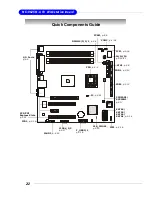
Page 18: ...1 p 2 6 CLR_CMOS1 p 2 19 BIOS SATA4 SATA3 SATA2 SATA1 p 2 14 IDE1 p 2 13 F_USB2 1 p 2 18 PCI PCI Express Slots p 2 22 J1394_1 2 p 2 17 CPUFAN1 SYSFAN1 p 2 17 JCI1 p 2 16 JCD1 p 2 16 JAUD1 p 2 15 JFP1...

Page 19: ...uter For more information on compatible components please visit http www msi com tw program products server svr pro_svr_qvl php MSI Reminds You Overheating Overheating will seriously damage the CPU an...

Page 20: ...Make sure to align the gold arrow on the CPU with the arrow key on the socket 2 Push the CPU down until its pins securely fit into the socket CPU Cooler Set Installation 3 On the front end of the CPU...

Page 21: ...ention mechanism 6 Hook the other end of the clip to the re tention mechanism and press the lever down to close 7 Follow the same procedures to install the second clip 8 Connect the fan power cable fr...

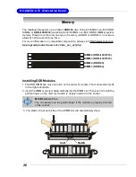
Page 22: ...utomatically close The mainboard supports up to 2GB of DDR333 two 184 pin 333MHz non ECC DDR DIMMs or DDR II 400 533 two 240 pin 400 533MHz non ECC DDR II DIMMs system memory Please note that only one...

Page 23: ...le or double sided modules depending on their needs Please note that only one type of memory all DDR or all DDR II no mixture allowed can be used at one time MSI Reminds You Make sure that you install...

Page 24: ...power supply please plug your power supply along with pin 1 pin 13 refer to the image at the right hand There is also a foolproof design on pin 11 12 23 24 to avoid wrong installation SSI 8 Pin CPU Po...

Page 25: ...11 N C 12 SDA 13 Horizontal Sync 14 VerticalSync 15 SCL Mouse Connector Green Keyboard Connector Purple The mainboard provides a standard PS 2 mouse keyboard mini DIN connector for attaching a PS 2 m...

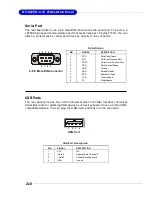
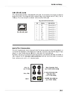
Page 26: ...A high speed communication port that sends receives 16 bytes FIFOs You can attach a serial mouse or other serial devices directly to the connector PIN SIGNAL DESCRIPTION 1 DCD Data Carry Detect 2 SIN...

Page 27: ...dio devices Mic is a connector for microphones However there is an advanced audio application provided by Realtek ALC880 to offer support for 7 1 channel audio operation and can turn rear audio connec...

Page 28: ...Port ECP mode 13 1 14 25 PIN SIGNAL DESCRIPTION 1 STROBE Strobe 2 DATA0 Data0 3 DATA1 Data1 4 DATA2 Data2 5 DATA3 Data3 6 DATA4 Data4 7 DATA5 Data5 8 DATA6 Data6 9 DATA7 Data7 10 ACK Acknowledge 11 B...

Page 29: ...to the hard disk docu mentation supplied by hard disk vendors for jumper setting instructions IDE1 Primary IDE Connector IDE1 can connect a Master and a Slave drive You must configure the second hard...

Page 30: ...ds You Please do not fold the Serial ATA cable into 90 degree angle Otherwise the loss of data may occur during transmission Serial ATA Connectors SATA1 SATA2 SATA3 SATA4 This mainboard provides four...

Page 31: ...will not function 5 6 10 9 JAUD1 Pin Definition PIN SIGNAL DESCRIPTION 1 PORT 1L Analog Port 1 Left channel 2 GND Ground 3 PORT 1R Analog Port 1 Right channel 4 PRESENCE Active low signal signals BIOS...

Page 32: ...front panel switches and LEDs The JFP1 is compliant with Intel Front Panel I O Connectivity Design Guide CD In Connector JCD1 The connector is for CD ROM audio connector JCD1 GND R L JCI1 1 2 9 10 JF...

Page 33: ...ensor to take advantage of the CPU fan control CPUFAN1 SENSOR 12V GND IEEE 1394 Connectors J1394_1 J1394_2 The mainboard provides two 1394 pin headers that allow you to connect IEEE 1394 ports via an...

Page 34: ...to F_USB1 or F_USB2 the USB pinheader in YELLOW color USB 2 0 Bracket Optional 1 2 9 10 F_USB1 F_USB2 PIN SIGNAL PIN SIGNAL 1 VCC 2 VCC 3 USB0 4 USB1 5 USB0 6 USB1 7 GND 8 GND 9 Key no pin 10 USBOC Pi...

Page 35: ...the system is off Then return to 1 2 pin position Avoid clearing the CMOS while the system is on it will damage the mainboard Clear CMOS Jumper CLR_CMOS1 There is a CMOS RAM on board that has a power...

Page 36: ...e two jumpers specify the FSB frequency of the onboard CPU To ensure system stability make sure that these jumpers are properly set to correspond with your CPU s FSB frequency J4 1 J5 1 J5 Dothan B Do...

Page 37: ...way to enhance graphics performance J3 1 1 05V for add on VGA card 1 05V for onboard Intel 915GM GMCH lower performance 1 Short Pin 1 2 1 05V 1 Short Pin 2 3 Auto Detect 1 05V for add on VGA card 1 5V...

Page 38: ...desktop platforms with PCI Express Architecture will be designed to deliver highest performance in video graphics multimedia and other sophisticated applications Moreover PCI Express architecture prov...

Page 39: ...are hardware lines over which devices can send interrupt signals to the microprocessor The PCI IRQ pins are typically connected to the PCI bus pins as follows DEVICE ICH INT Pin IDSEL CLOCK REQ GNT PC...

Page 40: ...n this chapter are under continuous update for better system performance Therefore the description may be slightly different from the lat est BIOS and should be held for reference only 2 Upon boot up...

Page 41: ...he RESET button You may also restart the system by simultaneously pressing Ctrl Alt and Delete keys Move to the previous item Move to the next item Move to the item in the left hand Move to the item i...

Page 42: ...s that means a sub menu can be launched from this field A sub menu contains additional options for a field parameter You can use arrow keys to highlight the field and press Enter to call up the sub me...

Page 43: ...the settings Main Use this menu for basic system configurations such as time date etc Advanced Use this menu to set up the items of special enhanced features available on your system s chipset Securit...

Page 44: ...nd use the or key to switch to the value you prefer Date mm dd yy The date format is Day Month Date Year Time hh mm ss The time format is Hour Minute Second IDE Channel 0 1 2 3 Master Slave These fiel...

Page 45: ...ded into several sub menus Each sub menu provides more settings To enter the sub menu highligh the sub menu you want to configure and press Enter Advanced Advanced Chipset Features The sub menu is use...

Page 46: ...o set the number of cycles for a timing delay between the CAS and RAS strobe signals used when DRAM is written to read from or refreshed Fast speed offers faster performance while slow speed offers mo...

Page 47: ...appears OnChip IDE Device Press Enter to enter the sub menu and the following screen appears On Chip Serial ATA This setting specifies the function of the on chip SATA controller Disabled Disable SATA...

Page 48: ...abled as well PCI Slot 1 PCI Slot 2 These settings disable enable the specified PCI devices PCI E Compliancy Mode This setting specifies the PCI Express compliancy mode USB Controller This setting is...

Page 49: ...rs Onboard FDC Controller Select Enabled if your system has a floppy disk controller FDD installed on the system board and you wish to use it If you install add on FDC or the system has no floppy driv...

Page 50: ...se DMA The ECP mode has to use the DMA channel so choose the onboard parallel port with the ECP feature After selecting it the following message will appear ECP Mode Use DMA At this time the user can...

Page 51: ...rgy The information stored in memory will be used to restore the system when a wake up event occurs USB KB Wake Up from S3 This setting allows you to enter Any Key max 8 numbers to wake up the system...

Page 52: ...n1 CPUFan1 Tolerance Value Current System CPU Temperature System Fan1 CPU Fan1 Speed Vcore VCC3 VCC_DDR 12V VCC V VBAT V 5VSB V These items display the current status of all of the monitored hardware...

Page 53: ...ting is to set the Num Lock status when the system is powered on Setting to On will turn on the Num Lock key when the system is powered on Setting to Off will allow users to use the arrow keys on the...

Page 54: ...is the greater the EMI is reduced and the system will become less stable For the most suitable Spread Spectrum value please consult your local EMI regulation 3 Remember to disable Spread Spectrum if...

Page 55: ...this menu to set Supervisor Password Set User Password Use this menu to set User Password Security Option This specifies the type of BIOS password protection that is implemented Settings are described...

Page 56: ...3 17 BIOS Setup Server This section shows the overall hardware specifications of your system System Summary Press Enter to view the hardware specifications of your system...

Page 57: ...e screen at boot ot Halt On The setting determines whether the system will stop if an error is detected at boot Available options are All Errors The system stops when any error is detected No Errors T...

Page 58: ...to move it up down in the priority list First Boot Device Second Boot Device Third Boot Device The items allow you to set the sequence of boot devices where BIOS attempts to load the disk operating sy...

Page 59: ...load the default values set by the mainboard manufacturer specifi cally for optimal performance of the mainboard Save Exit Setup Save changes to CMOS and exit setup Exit Without Saving Abandon all ch...

Page 60: ...ed with Realtek ALC880 chip which provides support for 8 channel audio output including 2 Front 2 Rear 1 Center and 1 Subwoofer channel ALC880 allows the board to attach 2 4 6 or 8 speakers for better...

Page 61: ...r Windows XP you must install Windows XP Service Pack1 or later before installing the driver The following illustrations are based on Windows XP environment and could look slightly different if you in...

Page 62: ...A 3 Realtek ALC880 8 Channel Audio Function 4 Click Finish to restart the system 3 Click Next to install the Realtek High Definition Audio Driver Click here Click here Select this option...

Page 63: ...le to use the 2 4 6 or 8 channel audio feature now Click the audio icon from the system tray at the lower right corner of the screen to activate the HD Audio Configuration It is also available to enab...

Page 64: ...emove a preset EQ setting There are also other pre set equalizer models for you to choose by clicking Others under the Equalizer part Here you can select a sound effect you like from the Environment l...

Page 65: ...Hz Save The settings are saved permanently for future use Reset 10 bands of equalizer would go back to the default setting Enable Disable To disable you can tem porarily stop the sound effect without...

Page 66: ...d while the background music is still in place and you can be that singer 2 Key Adjustment Using Up Down Arrow to find a key which better fits your vocal range Raise the key Lower the key Remove the h...

Page 67: ...ely from the indicated real panel or front panel This feature is very helpful when 2 people are using the same computer together for different purposes Click the button and the Mixer ToolBox menu will...

Page 68: ...be played from the rear panel which is the default setting Then you must to select the Realtek HD Audio front output from the scroll list first and use a different program to play the second audio so...

Page 69: ...13 items to be chosen Advanced controls Enable playback multi streaming With this function you will be able to have an audio chat with your friends via head phone stream 1 from front panel while stil...

Page 70: ...Advanced control is a Microphone Boost icon Once this item is checked you will find advanced icon beside Front Pink In Mic Volume With this the input signal into Front Pink In Mic Volume will be stren...

Page 71: ...start recording in this case If you d like to connect your microphone to the front audio panel You may control the microphone volume by Mic Volume or front mic in on the mixer MSI Reminds You Only th...

Page 72: ...able to be chosen to perform either output i e playback function or input i e Recording function we call this Retasking 1 Audio I O aims to help you set jacks right Moreover other than blue to blue pi...

Page 73: ...le and the dialogue connected device pops up the default setting of blue jack is Line in Check the headphone anyway then click OK You should notice the icon beside blue jack remains the same without a...

Page 74: ...that is playing from the back panel will be stopped 2 Disable front panel jack detection option Find no function on front panel jacks Please check if front jacks on your system are so called AC 97 jac...

Page 75: ...al signal pre vents the quality of the signal from degrading when it is converted to analog 1 Output Sampling Rate 44 1KHz This is recommended while playing CD 48KHz This is recommended while playing...

Page 76: ...ill light up and make testing sound If any speaker fails to make sound then check whether the cable is inserted firmly to the connector or replace the bad speakers with good ones Or you may click the...

Page 77: ...rophone Select the Noise Suppres sion to remove the possible noise during recording or select Acoustic Echo Cancelltion to cancel the acoustic echo druing recording Also please use the drop down list...

Page 78: ...nel Audio Function 3D Audio Demo In this tab you may adjust your 3D positional audio before playing 3D audio applica tions like gaming You may also select different environment to choose the most suit...

Page 79: ...ersion Audio Controller Audio Codec You may also select the language of this utility by choosing from the Language list Also there is a selection Show icon in system tray Switch it on and an icon will...

Page 80: ...the front panel according to Chapter 2 2 Select AC97 or Azalia in the BIOS setting Chapter 3 3 If you are using Azalia setting the microphone function on the front panel is fixed but the headphone jac...

Page 81: ...dance with the setting in software utility n 2 Channel Mode for Stereo Speaker Output Refer to the following diagram and caption for the function of each phone jack on the back panel when 2 Channel Mo...

Page 82: ...o back panel s Line Out connector and two speakers to the real chan nel Line Out connector 1 Line In 2 Line Out Front channels 3 MIC 4 Line Out Rear channels 5 Line Out Center and Subwoofer channel bu...

Page 83: ...l s Line Out connector two speakers to the rear channel and two speakers to the cen ter subwoofer channel Line Out connectors 6 Channel Analog Audio Output 1 Line In 2 Line Out Front channels 3 MIC 4...

Page 84: ...nnels 3 MIC 4 Line Out Rear channels 5 Line Out Center and Subwoofer channel 6 Optical SPDIF Out in 7 1CH 5 1CH Description Connect two speakers to back panel s Line Out connector two speakers to the...

Page 85: ...in command Intel ICH6R includes the RAID level 0 striping RAID level 1 mirroring and a combi nation of the two called Intel Matrix RAID Technology which has two volume in two hard disk RAID 0 breaks t...

Page 86: ...AID for details to create delete and reset RAID volumes After the above message shows press Ctrl and I keys simultaneously to enter the RAID Configuration Utility Using the Intel RAID Option ROM 1 Cre...

Page 87: ...e RAID Volume 1 Select option 1 Create RAID Volume and press Enter key The following screen appears Then in the Name field specify a RAID Volume name and then press the TAB or Enter key to go to the n...

Page 88: ...e available values and pressing the Enter key to select and advance to the next field The avail able values range from 4KB to 128 KB in power of 2 increments The strip value should be chosen based on...

Page 89: ...is finished MSI Reminds You Since you want to create two volumes Intel Matrix RAID Technology this default size maximum needs to be reduced Type in a new size for the first volume As an example if yo...

Page 90: ...te RAID Volume from the main menu window and press Enter key to select a RAID volume for deletion Then press Delete key to delete the selected RAID volume The following screen appears Press Y key to a...

Page 91: ...ructures from the drives The following screen appears Press Y key to accept the selection MSI Reminds You 1 You will lose all data on the RAID drives and any internal RAID structures when you perform...

Page 92: ...allation or if you need to specify any additional devices to be installed do so at this time Once all devices are specified press Enter to continue with installation 6 From the Windows XP 2000 Setup s...

Page 93: ...hard drive from which the system is booting or a hard drive that contains important data For this reason you cannot remove or un install this driver from the system after installation however you wil...

Page 94: ...B 10 MS 9625 M ATX Workstation Board The InstallShield Wizard will begin automatically for installation showed as following Click on the Next button to proceed the installation in the welcoming window...

Page 95: ...B 11 Intel ICH6R SATA RAID After reading the license agreement in the following window click Yes button to continue The window shows the components to be installed Click Next button to continue...

Page 96: ...Board Select a program folder in the following window where you want Setup to add the program icon Select the folder in which you want the program to be installed in the following window and click Nex...

Page 97: ...B 13 Intel ICH6R SATA RAID Once the installation is complete the following window appears The following window appears to show the Intel Application Accelerator RAID Edition Setup installation status...

Page 98: ...plication Accelerator RAID Driver during Windows Setup Refer to P 5 8 Installing Software for instructions on installing the driver during Windows Setup 3 Install the Intel Application Accelerator RAI...

Page 99: ...rom Existing Disk To create a RAID volume from an existing disk choose Action Create RAID Volume from Existing Hard Drive The Create RAID Volume from Existing Hard Drive Wizard pops up to lead you for...

Page 100: ...ptimized for data redundancy will pro vide you with a realtime duplicate copy of your data Note Only half of the available volume space will be available for data storage Strip Sizes Select the desire...

Page 101: ...urce disk the one containing all of the information to be migrated and which one is the target disk On a RAID Ready system this can be determined by making a note during POST of which port e g Port 0...

Page 102: ...member disk the target disk that you wish to use and then click to move it to the Selected field Then click Next to continue Please note that the existing data on the selected hard drive s will be del...

Page 103: ...he rest hard drive space will be worked as RAID 1 volume which is the new technology called Intel Matrix RAID Then click Next to continue 5 Start Creating RAID Volume from Existing Hard Drive Wizard B...

Page 104: ...While you can still continue using your computer during the migration process once the migration process starts it cannot be stopped If the migration process gets interrupted and your system is reboo...

Reviews: