background image

15

Overview of Components

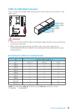
SATA1~6: SATA 6Gb/s Connectors

These connectors are SATA 6Gb/s interface ports. Each connector can connect to one 

SATA device.

SATA6

SATA3

SATA1

SATA4

SATA2

SATA5

 Important


y

Please do not fold the SATA cable at a 90-degree angle. Data loss may result during 

transmission otherwise.


y

SATA cables have identical plugs on either sides of the cable. However, it is 

recommended that the flat connector be connected to the motherboard for space 

saving purposes.

M.2/ SATA ports & PCIe slots combination table

Slot

Available SATA connectors

M2_1

PCIe x2

PCIe x4

SATA

SATA1

SATA2

SATA3

SATA4

SATA5

SATA6

PCI_E3

PCI_E4

(

SATA

: M.2 SATA SSD, 

PCIe x2

: M.2 PCIe x2 SSD, 

PCIe x4

: M.2 PCIe x4 SSD,  

: available, 

: unavailable)

Summary of Contents for 970A GAMING PRO CARBON

Page 1: ...ur Installation Ihres Computers Manche Installationen bieten auch die Videodemonstrationen Klicken Sie auf die URL um diese Videoanleitung mit Ihrem Browser auf Ihrem Handy oder Table anzusehen Oder s...

Page 2: ...II Quick Start 1 6 7 8 2 3 4 5 http youtu be zGR s3xgPik Installing a Processor Installation des Prozessors Installer un processeur...

Page 3: ...III Quick Start http youtu be 76yLtJaKlCQ 1 2 2 3 Installing DDR3 memory Installation des DDR3 Speichers Installer une m moire DDR3 DDR3...

Page 4: ...Switch 7 Reset Switch 8 Power Switch 9 Reserved 10 No Pin R E S E T S W P O W E R S W P O W E R L E D P O W E R L E D H D D L E D HDD LED RESET SW JFP1 HDD LED HDD LED HDD LED POWER LED POWER LED POW...

Page 5: ...V Quick Start 1 2 Installing the Motherboard Installation des Motherboards Installer la carte m re...

Page 6: ...VI Quick Start 1 2 3 4 5 http youtu be RZsMpqxythc Installing SATA Drives Installation der SATA Laufwerke Installer le disque dur SATA SATA...

Page 7: ...VII Quick Start 1 4 5 http youtu be mG0GZpr9w_A 2 3 Installing a Graphics Card Einbau der Grafikkarte Installer une carte graphique...

Page 8: ...VIII Quick Start Connecting Peripheral Devices Peripherieger te Connecter un p riph rique anschliessen...

Page 9: ...IX Quick Start http youtu be gkDYyR_83I4 ATX_PWR1 CPU_PWR1 Connecting the Power Connectors Stromanschl sse anschliessen Connecter les c bles du module d alimentation...

Page 10: ...X Quick Start 1 4 2 3 Power On Einschalten Mettre sous tension...

Page 11: ...USB 3 1 Gen1 Connectors 17 JFP1 JFP2 Front Panel Connectors 17 JUSB1 3 USB 2 0 Connectors 18 JTPM1 TPM Module Connector 18 CPU_FAN1 SYS_FAN1 4 Fan Connectors 19 JAUD1 Front Audio Connector 20 JCI1 Cha...

Page 12: ...computer before installation is completed This could cause permanent damage to the components as well as injury to the user y If you need help during any installation step please consult a certified c...

Page 13: ...upports 2242 2260 2280 storage devices M 2 and SATA ports maximum support 1x M 2_PCIe 6x SATAs or 1x M 2_ SATA 5x SATAs Please refer to page 15 for M 2 SATA ports PCIe slots combination table When ins...

Page 14: ...USB 2 0 connectors supports additional 6 USB 2 0 ports y 2x USB 3 1 Gen1 connectors supports additional 4 USB 3 1 Gen1 ports y 1x 4 pin CPU fan connector y 2x 4 pin system fan connectors y 2x 3 pin s...

Page 15: ...NTER y LIVE UPDATE 6 y FAST BOOT y SUPER CHARGER y GAMING APP y USB SPEED UP y GAMING LAN MANAGER y Nahimic 2 y Open Broadcaster Software y Norton Internet Security Solution y Google Chrome Google Too...

Page 16: ...System Mode Switching OC Gaming Silent Gaming Hotkey Gaming Mouse Control Gaming LED Control y Optimized Thermal Design Heat pipe Direct Touch Technology Enhanced Choke Thermal Design y Nahimic 2 Sou...

Page 17: ...itary Class Stability and Reliability ESD Protection EMI Protection Humidity Protection Circuit Protection High Temperature Protection VGA Armor Slot y COMMAND CENTER System Monitor Smart Fan Control...

Page 18: ...Off No link Yellow Linked Blinking Data activity Speed LED Status Description Off 10 Mbps connection Green 100 Mbps connection Orange 1 Gbps connection LAN Port LED Status Table Audio Ports Configurat...

Page 19: ...Rear I O Panel Audio jacks to headphone and microphone diagram Audio jacks to stereo speakers diagram Audio jacks to 7 1 channel speakers diagram AUDIO INPUT AUDIO INPUT Rear Front Side Center Subwoof...

Page 20: ...1 CPU Socket DIMMA1 DIMMA2 DIMMB1 DIMMB2 ATX_PWR1 EZ Debug LED CPU_PWR1 JBAT1 JUSB5 JUSB2 JUSB1 JUSB4 JUSB3 JFP2 JFP1 SYS_FAN3 SYS_FAN1 SYS_FAN2 SYS_FAN4 JSP1 JTPM1 JCOM1 JLED1 JAUD1 PCI1 PCI_E5 M2_1...

Page 21: ...atsink A CPU heatsink is necessary to prevent overheating and maintain system stability y Confirm that the CPU heatsink has formed a tight seal with the CPU before booting your system y Overheating ca...

Page 22: ...e less than the amount of installed y Please note that the maximum capacity of addressable memory is 4GB or less for 32 bit Windows OS due to the memory address limitation Therefore we recommended tha...

Page 23: ...lot is recommended y When adding or removing expansion cards always turn off the power supply and unplug the power supply power cable from the power outlet Read the expansion card s documentation to c...

Page 24: ...be JCTFABytrYA Installing M 2 module M2_1 M 2 Slot 1 2 3 30 3 Tighten the base screw into the hole of the distance to the M 2 slot as the length your M 2 module 4 Insert your M 2 module into the M 2...

Page 25: ...loss may result during transmission otherwise y SATA cables have identical plugs on either sides of the cable However it is recommended that the flat connector be connected to the motherboard for spa...

Page 26: ...2V 2 Ground 6 12V 3 Ground 7 12V 4 Ground 8 12V Important Make sure that all the power cables are securely connected to a proper ATX power supply to ensure stable operation of the motherboard CPU_PWR1...

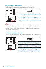
Page 27: ...USB3_TX_C_DP 16 Ground 7 Ground 17 USB3_RX_DP 8 USB2 0 18 USB3_RX_DN 9 USB2 0 19 Power 10 NC 20 No Pin Important Note that the Power and Ground pins must be connected correctly to avoid possible dama...

Page 28: ...is for TPM Trusted Platform Module Please refer to the TPM security platform manual for more details and usages JUSB1 3 USB 2 0 Connectors These connectors allow you to connect USB 2 0 ports on the fr...

Page 29: ...the fan speed will be always maintained at 100 and that could be noisy 1 CPU_FAN1 1 Ground 2 12V 3 Sense 4 Speed Control Signal 1 SYS_FAN1 SYS_FAN2 1 Ground 2 Voltage Control 3 Sense 4 NC PWM Mode fan...

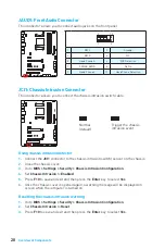
Page 30: ...intrusion detector 1 Connect the JCI1 connector to the chassis intrusion switch sensor on the chassis 2 Close the chassis cover 3 Go to BIOS Settings Security Chassis Intrusion Configuration 4 Set Cha...

Page 31: ...for digital audio transmission Important y This connector supports 5050 RGB multi color LED strips 12V G R B within 2 meters y Always turn off the power supply and unplug the power cord from the powe...

Page 32: ...computer and unplug the power cord 2 Use a jumper cap to short JBAT1 for about 5 10 seconds 3 Remove the jumper cap from JBAT1 4 Plug the power cord and power on the computer EZ Debug LED Debug LED in...

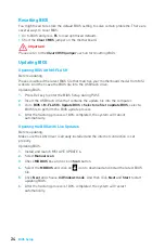
Page 33: ...hapter are for reference only and may vary from the product you purchased Entering BIOS Setup Please refer the following methods to enter BIOS setup y Press Delete key when the Press DEL key to enter...

Page 34: ...t the USB flash drive that contains the update file into the computer 3 Go to BIOS M FLASH Update BIOS Select one file to update BIOS select a BIOS file to perform the BIOS update process 4 After the...

Page 35: ...Virtual OC Genie Button enables or disables the OC Genie function by clicking on this button When enabled this button will be light Enabling OC Genie function can automatically overclock with MSI opt...

Page 36: ...llows you to set the CPU FSB frequency in MHz You may overclock the CPU by adjusting this value Please note that overclocking behavior and stability is not guaranteed f Adjust CPU Ratio Auto Sets the...

Page 37: ...ink or Unlink in DRAM Timing Mode User can set the memory timing for each memory channel The system may become unstable or unbootable after changing memory timing If it occurs please clear the CMOS da...

Page 38: ...ated to components If set to Auto BIOS will set these voltages automatically or you can set it manually f Spread Spectrum Disabled This function reduces the EMI Electromagnetic Interference generated...

Page 39: ...Quiet function Auto Depends on AMD Design Enable Enables AMD Cool n Quiet function The Cool n Quiet technology can effectively and dynamically lower CPU speed and power consumption Disabled Disables t...

Page 40: ...g Drivers 1 Start up your computer in Windows 7 8 1 10 2 Insert MSI Driver Disc into your optical drive 3 The installer will automatically appear and it will find and list all necessary drivers 4 Clic...

Page 41: ...ectors 17 JFP1 JFP2 Frontpanel Anschl sse 17 JUSB1 3 USB 2 0 Anschl sse 18 JTPM1 TPM Anschluss 18 CPU_FAN1 SYS_FAN1 4 Stromanschl sse f r L fter 19 JAUD1 Audioanschluss des Frontpanels 20 JCI1 Geh use...

Page 42: ...er nicht bevor die Installation abgeschlossen ist Dies k nnte permanente Sch den an den Komponenten sowie zu das Verletzung des Benutzers verursachen y Sollten Sie Hilfe bei der Installation ben tigen...

Page 43: ...tzt 2242 2260 2280 Speicherger te M 2 und SATA und SATAe Anschl sse unterst tzen maximal 1x M 2_PCIe 6x SATAs oder 1x M 2_SATA 5x SATAs Auf Seite 15 finden Sie eine Anleitung f r verschiedene M 2 SAT...

Page 44: ...TX12V Stromanschluss x1 y SATA 6Gb s Anschl sse x6 y USB 2 0 Anschl sse x3 unterst tzt zus tzliche 6 USB 2 0 Ports y USB 3 1 Gen1 Anschl sse x2 unterst tzt zus tzliche 4 USB 3 1 Gen1 Ports y 4 poliger...

Page 45: ...y LIVE UPDATE 6 y FAST BOOT y SUPER CHARGER y GAMING APP y USB SPEED UP y GAMING LAN MANAGER y Nahimic 2 y Open Broadcaster Software y Norton Internet Security Solution y Google Chrome Google Toolbar...

Page 46: ...schalten OC Gaming Silent Gaming Hotkey Gaming Maussteuerung Gaming LED Steuereinheit y Optimierte W rmetechnologie Heat Pipe Direct Touch Technologie Verbessertes Thermaldesign der Spulen y Nahimic 2...

Page 47: ...enten Military Class Stabilit t und Zuverl ssigkeit ESD Schutz EMI Schutz Luftfeuchtigkeit Schutz Schaltkreisschutz bertemperaturschutz VGA Armor Steckplatz y COMMAND CENTER System Monitor Smart L fte...

Page 48: ...ng Gelb Verbindung Blinkt Datenaktivit t Geschwindigkeit LED Zustand Bezeichnung Aus 10 Mbps Verbindung Gr n 100 Mbps Verbindung Orange 1 Gbps Verbindung LAN Port LED Zustandstabelle Konfiguration der...

Page 49: ...ckseite E A Audiobuchsen f r den Anschluss von einem Kopfh rer und Mikrofon Audiobuchsen f r Stereo Lautsprecher Audiobuchsen f r 7 1 Kanal Anlage AUDIO INPUT AUDIO INPUT Rear Front Side Center Subwoo...

Page 50: ...AN1 CPU Sockel DIMMA1 DIMMA2 DIMMB1 DIMMB2 ATX_PWR1 EZ Debug LED CPU_PWR1 JBAT1 JUSB5 JUSB2 JUSB1 JUSB4 JUSB3 JFP2 JFP1 SYS_FAN3 SYS_FAN1 SYS_FAN2 SYS_FAN4 JSP1 JTPM1 JCOM1 JLED1 JAUD1 PCI1 PCI_E5 M2_...

Page 51: ...tabilit t zu gew hrleisten y Stellen Sie sicher dass Ihr K hlk rper eine feste Verbindung mit der CPU hergestellt hat bevor Sie Ihr System starten y berhitzung besch digt die CPU und das System nachha...

Page 52: ...Gr e der installierten Speicherkapazit t y Bitte beachten Sie dass die maximale Kapazit t eines 32 Bit Windows Betriebssystem bei 4GB oder weniger liegt Wenn Sie mehr als 4 GB Speicher auf dem Motherb...

Page 53: ...CI_E2 Steckplatz zu verwenden y Achten Sie darauf dass Sie den Strom abschalten und das Netzkabel aus der Steckdose herausziehen bevor Sie eine Erweiterungskarte installieren oder entfernen Lesen Sie...

Page 54: ...e JCTFABytrYA Installation eines M 2 Moduls M2_1 M 2 Steckplatz 1 2 3 30 3 Befestigen Sie den Schraubsockel in dem Loch welches zur L nge des M 2 Moduls passt 4 Stecken Sie das M2 Modul in den M2 Stec...

Page 55: ...TA Kabel nicht in einem 90 Winkel Datenverlust k nnte die Folge sein y SATA Kabel haben identische Stecker an beiden Enden Es wird empfohlen den flachen Stecker auf dem Motherboard einstecken M 2 SATA...

Page 56: ...Ground 7 12V 4 Ground 8 12V Wichtig Stellen Sie sicher dass alle Anschl sse mit den richtigen Anschl ssen des Netzteils verbunden sind um einen stabilen Betrieb der Hauptplatine sicherzustellen CPU_PW...

Page 57: ...ound 7 Ground 17 USB3_RX_DP 8 USB2 0 18 USB3_RX_DN 9 USB2 0 19 Power 10 NC 20 No Pin Wichtig Bitte beachten Sie dass Sie die mit Stromf hrende Leitung und Erdleitung bezeichneten Pins korrekt verbinde...

Page 58: ...er den Einsatz des optionalen TPM Modules entnehmen Sie bitte dem TPM Plattform Handbuch JUSB1 3 USB 2 0 Anschl sse Mit diesen Anschl ssen k nnen Sie die USB 2 0 Anschl sse auf dem Frontpanel verbinde...

Page 59: ...fteranschluss anschlie en l uft der L fter mit h chster Drehzahl und kann unangenehm laut werden 1 CPU_FAN1 1 Ground 2 12V 3 Sense 4 Speed Control Signal 1 SYS_FAN1 SYS_FAN2 1 Ground 2 Voltage Control...

Page 60: ...s am Geh usekontakt Schalter Sensor am Geh use an 2 Schlie en Sie die Geh useabdeckung 3 Gehen Sie zu BIOS Settings Security Chassis Intrusion Configuration 4 Stellen Sie Chassis Intrusion auf Enabled...

Page 61: ...digitaler Audiodaten verwendet Wichtig y Dieser Anschluss unterst tzt die 5050 RGB Mehr Farb LED Streifen 12V G R B bis maximal 2Meter y Schalten Sie die Stromversorgung aus und ziehen Sie das Netzkab...

Page 62: ...n Computer ab und ziehen Sie das Netzkabel ab 2 Verwenden Sie eine Steckbr cke um JBAT1 f r 5 10 Sekunden kurzzuschlie en 3 Entfernen Sie die Steckbr cke von JBAT1 4 Stecken Sie das Kabel Ihres Comput...

Page 63: ...ich Referenzen dar und k nnen von dem von Ihnen erworbenen Produkt abweichen ffnen des BIOS Setups Befolgen Sie bitte die nachfolgende Schritte um das BIOS Setup aufzurufen y W hrend des BOOT Vorgangs...

Page 64: ...2 Schlie en das USB Flashlaufwerk mit der BIOS Datei an den Computer 3 Gehen Sie zu BIOS M Flash Update BIOS Select one file to update BIOS W hlen Sie die BIOS Datei zur Durchf hrung des BIOS Aktuali...

Page 65: ...sind y Virtual OC Genie Taste Aktivieren oder deaktivieren Sie die OC Genie Funktion durch einen Klick auf diese Taste Wenn aktiviert leuchtet diese Taste auf Aktivieren Sie die OC Genie Funktion mit...

Page 66: ...Frequency Zeigt die derzeitigen Frequenz der installierten CPU und Speicher Dies ist nur eine Anzeige keine nderung m glich f Adjust CPU FSB Frequency Hier k nnen Sie die CPU FSB Frequenz ver ndern i...

Page 67: ...der Einstellung Link oder Unlink in DRAM Timing Mode aktiviert werden Der Anwender kann die Speicher Timing f r jeden Kanal des Speichers einstellen Das System k nnte nach dem ndern Speicher Timings...

Page 68: ...ng auf Auto gesetzt ist wird das BIOS die Spannungen automatisch einstellen oder Sie k nnen es manuell einstellen f Spread Spectrum Disabled Diese Funktion reduziert die EMI Electromagnetic Interferen...

Page 69: ...t oder deaktiviert die AMD Cool n Quiet Funktion Auto Abh ngig von AMD Design Empfehlung Enable Aktiviert die AMD Cool n Quiet Funktion Die Cool n Quiet Technologie kann die CPU Geschwindigkeit und de...

Page 70: ...e Ihren Computer mit Windows 7 8 1 10 2 Legen Sie die MSI Treiber Disk in das optisches Laufwerk 3 Der Installer wird automatisch erscheint und findet und finden Sie die ben tigten Treiber in die List...

Page 71: ...3 1 Gen1 17 JFP1 JFP2 Connecteurs de panneau avant 17 JUSB1 3 Connecteurs USB 2 0 18 JTPM1 Connecteur de module TPM 18 CPU_FAN1 SYS_FAN1 4 Connecteurs pour ventilateurs 19 JAUD1 Connecteur audio avant...

Page 72: ...ien fix s sur la carte m re ou ailleurs dans le bo tier de l ordinateur y Ne d marrez pas l ordinateur avant d avoir termin l installation Ceci peut endommager les composants ou vous blesser y Si vous...

Page 73: ...age 2242 2260 2280 Les ports M 2 et SATA supportent au maximum 1 SSD M 2 PCIe 6 SATA ou 1 SSD M 2 SATA 5 SATA R f rez vous la page 15 pour le tableau de combinaison des ports M 2 SATA et des slots PCI...

Page 74: ...SATA 6 Gb s y 3 x connecteurs USB 2 0 support de 6 autres ports USB 2 0 y 2 x connecteurs USB 3 1 Gen1 support de 4 autres ports USB 3 1 Gen1 y 1 x connecteur de ventilateurs CPU 4 broches y 2 x conn...

Page 75: ...y LIVE UPDATE 6 y FAST BOOT y SUPER CHARGER y GAMING APP y USB SPEED UP y GAMING LAN MANAGER y Nahimic 2 y Open Broadcaster Software y Norton Internet Security Solution y Google Chrome Google Toolbar...

Page 76: ...ation OC Gaming Silent Raccourcis Gaming Contr le de la souris Gaming Contr le de la LED Gaming y Refroidissement intelligent Technologie Heat pipe Direct Touch Refroidissement Enhanced Choke y Techno...

Page 77: ...Stabilit et fiabilit Protection contre les d charges lectrostatiques Protection contre les interf rences lectromagn tiques Protection contre l humidit Protection du circuit Protection contre la hauss...

Page 78: ...exion correcte Clignote Activit en cours LED indiquant la vitesse Etat Description Eteint D bit de 10 Mbps Vert D bit de 100 Mbps Orange D bit de 1 Gbps Tableau explicatif de l tat de la LED du port L...

Page 79: ...sation des ports audio d di s au casque et au microphone Ilustration de l utilisation du port audio d di aux haut parleurs Ilustration de l utilisation des ports audio d di s aux haut parleurs 7 1 AUD...

Page 80: ...FAN1 Socket processeur DIMMA1 DIMMA2 DIMMB1 DIMMB2 ATX_PWR1 EZ Debug LED CPU_PWR1 JBAT1 JUSB5 JUSB2 JUSB1 JUSB4 JUSB3 JFP2 JFP1 SYS_FAN3 SYS_FAN1 SYS_FAN2 SYS_FAN4 JSP1 JTPM1 JCOM1 JLED1 JAUD1 PCI1 PC...

Page 81: ...ut facilement endommager le processeur et la carte m re Assurez vous toujours que le syst me de refroidissement fonctionne correctement pour prot ger le processeur de la surchauffe Assurez vous d appl...

Page 82: ...noter que la capacit maximum de la m moire est de 4 Go ou moins pour le syst me d exploitation Windows 32 bit du fait de la limitation de m moire Par cons quent il est recommand d installer le syst m...

Page 83: ...CI_E2 pour profiter de performances optimales y Veillez toujours mettre l ordinateur hors tension et d brancher le cordon d alimentation avant d installer les cartes d extension R f rez vous la docume...

Page 84: ...sur l installation du module M 2 http youtu be JCTFABytrYA Installation du module M 2 M2_1 Slot M 2 1 2 3 30 3 Fixez la vis de base dans le trou correspondant la longueur du module M 2 4 Ins rez votr...

Page 85: ...ntra ner une perte de donn es pendant la transmission y Les c bles SATA disposent de prises identiques sur chaque c t N anmoins il est recommand de connecter la prise plate sur la carte m re pour un g...

Page 86: ...2 Ground 6 12V 3 Ground 7 12V 4 Ground 8 12V Important Veuillez vous assurer que tous les c bles d alimentation sont branch s aux connecteurs ad quats afin garantir une op ration stable de la carte m...

Page 87: ...Ground 7 Ground 17 USB3_RX_DP 8 USB2 0 18 USB3_RX_DN 9 USB2 0 19 Power 10 NC 20 No Pin Important Notez que les c bles d alimentation et de terre doivent tre branch s correctement afin d viter d endomm...

Page 88: ...m Module Veuillez vous r f rer au manuel du module TPM pour plus d informations JUSB1 3 Connecteurs USB 2 0 Ces connecteurs vous permettent de relier des ports USB 2 0 sur le panneau avant 1 2 10 9 1...

Page 89: ...M la vitesse sera toujours maintenue 100 et cela occasionnera du bruit 1 CPU_FAN1 1 Ground 2 12V 3 Sense 4 Speed Control Signal 1 SYS_FAN1 SYS_FAN2 1 Ground 2 Voltage Control 3 Sense 4 NC Connecteurs...

Page 90: ...ez le couvercle du bo tier 3 Allez dans le BIOS SETTINGS R glages Security S curit Chassis Intrusion Configuration Configuration intrusion ch ssis 4 R glez Chassis Intrusion intrusion ch ssis sur Enab...

Page 91: ...io num rique Important y Ce connecteur supporte des rubans LED RGB rouge vert bleu de type 5050 d une longueur de 2 m tres maximum y Avant d installer ou de retirer le ruban LED veillez toujours teind...

Page 92: ...lisez un couvercle de cavalier pour fermer JBAT1 pour environ 5 10 secondes 3 Enlevez le couvercle de cavalier du JBAT1 4 Branchez de nouveau le c ble d alimentation votre ordinateur et allumez le EZ...

Page 93: ...achetez Entrer dans l interface Setup du BIOS Pour entrer dans l interface Setup du BIOS vous pouvez suivre ces deux m thodes y Pendant le d marrage lorsqu appara t le message Press DEL key to enter S...

Page 94: ...ez sauvegarder le nouveau BIOS sur le lecteur flash USB Mettre le BIOS jour 1 Appuyez sur la touche Suppr pour entrer dans l interface Setup du BIOS pendant le processus de POST 2 Connectez le lecteur...

Page 95: ...nces M FLASH permet de mettre le BIOS jour avec un lecteur flash USB OC PROFILE permet de g rer les profils d overclocking HARDWARE MONITOR Moniteur de mat riel permet de r gler la vitesse des ventila...

Page 96: ...gauche droite y Information du syst me Cette partie affiche l heure la date le nom du CPU la fr quence CPU la fr quence DRAM la capacit DRAM et la version BIOS y Langue vous permet de choisir la langu...

Page 97: ...requency Vous permet de r gler la fr quence FSB du CPU en MHz Vous pouvez overclocker le CPU en ajustant cette valeur Veuillez noter que le comportement et la stabilit d overclocking ne sont pas garan...

Page 98: ...ur peut r gler la synchronisation de m moire pour chaque canal de m moire Le syst me peut tre instable ou ne peut plus red marrer apr s le changement de la synchronisation de la m moire Dans ce cas l...

Page 99: ...permet de d finir les tensions relatives aux composants En mode Auto le BIOS configure ces tensions automatiquement Vous pouvez galement les r gler manuellement f Spread Spectrum Disabled Cette foncti...

Page 100: ...e seule f CPU Features Appuyez sur la touche Entr e pour acc der au sous menu fAMD Cool n Quiet Auto Active ou d sactive la fonction AMD Cool n Quiet Auto D pend d AMD Design Enable Active la fonction...

Page 101: ...31 Con guration du BIOS fIOMMU Mode Active d sactive l IOMMU I O Memory Management Unit pour I O Virtualization...

Page 102: ...es 1 Allumez l ordinateur sous Windows 7 8 1 10 2 Ins rez le disque MSI Driver dans le lecteur optique 3 L outil d installation appara t automatiquement Il trouvera et listera tous les pilotes dont vo...

Page 103: ...15 CPU_PWR1 ATX_PWR1 16 JCOM1 16 JUSB4 5 USB 3 1 Gen1 17 JFP1 JFP2 17 JUSB1 3 USB 2 0 18 JTPM1 TPM 18 CPU_FAN1 SYS_FAN1 4 19 JAUD1 20 JCI1 20 JLED1 RGB LED 21 JSP1 S PDIF Out 21 JBAT1 CMOS BIOS 22 EZ...

Page 104: ...2 y y y y y y y y y y y y y y y y 60 C 140 F...

Page 105: ...D 5 RAID 10 SATA y 1 x M 2 M PCIe 2 0 x2 x4 SATA 6 2242 2260 2280 M 2 SATA 1x M 2_PCIe 6x SATA 1x M 2_SATA 5x SATA M 2 SATA PCIe 15 PCI_E3 PCI_E4 M 2_PCIe x4 PCI_E3 PCI_E4 M 2_PCIe x2 USB y ASMedia AS...

Page 106: ...1 x LAN RJ45 y 1 x S PDIF OUT y 6 x y 1 x 24 ATX y 1 x 8 ATX 12 y 6 x SATA 6 y 3 x USB 2 0 6 USB 2 0 y 2 x USB 3 1 Gen1 4 USB 3 1 Gen1 y 1 x 4 y 2 x 4 y 2 x 3 y 1 x y 2 x y 1 x TPM y 1 x y 1 x y 1 x...

Page 107: ...6 y FAST BOOT y SUPER CHARGER y GAMING APP y USB SPEED UP y GAMING LAN MANAGER y Nahimic 2 y Open Broadcaster Software y Norton Internet Security Solution y Google Chrome Google Toolbar Google Drive y...

Page 108: ...t GAMING Network Manager cFos y GAMING APP OC Gaming Silent Gaming Hotkey Gaming Mouse Control Gaming LED Control y Heat pipe Direct Touch Enhanced Choke Thermal Design y Nahimic 2 Sound Tracker HD Au...

Page 109: ...EZ Board Explorer y MILITARY CLASS 4 Military Class Military Class VGA Armor y COMMAND CENTER y EZ y LIVE UPDATE 6 y USB Redrivers y Steel Series Engine 3 y SUPER CHARGER y USB 3 1 Gen2 Type A Type C...

Page 110: ...8 PS 2 LAN USB 2 0 S PDIF Out USB 3 1 Gen2 Type C USB 3 1 Gen2 10 100 1 LAN 2 4 6 8...

Page 111: ...9 7 1 AUDIO INPUT AUDIO INPUT Rear Front Side Center Subwoofer...

Page 112: ...MMB1 DIMMB2 ATX_PWR1 EZ Debug LED CPU_PWR1 JBAT1 JUSB5 JUSB2 JUSB1 JUSB4 JUSB3 JFP2 JFP1 SYS_FAN3 SYS_FAN1 SYS_FAN2 SYS_FAN4 JSP1 JTPM1 JCOM1 JLED1 JAUD1 PCI1 PCI_E5 M2_1 JCI1 PCI_E4 PCI_E3 PCI_E2 PCI...

Page 113: ...11 AM3 AM3 AM3 AM3 CPU 1 y y MSI y y y y y MSI...

Page 114: ...12 DIMM DIMMA1 DIMMB1 A B DIMMA2 DIMMB2 DIMMB1 DIMMB2 DIMMB1 DIMMA1 DIMMA1 DIMMA2 DIMMA1 y DIMMA1 y y 32 Windows 4 4 64 Windows y y...

Page 115: ...3 PCI_E1 5 PCI1 PCIe PCI PCI_E1 PCIe 2 0 x1 PCI_E2 PCIe 2 0 x16 PCI_E3 PCIe 2 0 x1 PCI_E4 PCIe 2 0 x1 PCI_E5 PCIe 2 0 x8 PCI1 PCI y PCIe x16 PCI_E2 y y MSI Gaming Series Graphics Card Bolster X16 X8 X...

Page 116: ...14 Intel RST PCIe M 2 SSD UEFI ROM Legacy ROM M 2 http youtu be JCTFABytrYA M 2 M2_1 M 2 1 2 3 30 3 2 4 2 2 30 5 M 2 1 2 4 5...

Page 117: ...TA 6 SATA SATA6 SATA3 SATA1 SATA4 SATA2 SATA5 y SATA y SATA M 2 SATA PCIe SATA M2_1 PCIe x2 PCIe x4 SATA SATA1 SATA2 SATA3 SATA4 SATA5 SATA6 PCI_E3 PCI_E4 SATA M 2 SATA SSD PCIe x2 M 2 PCIe x2 SSD PCI...

Page 118: ...7 Ground 6 5V 18 Ground 7 Ground 19 Ground 8 PWR OK 20 Res 9 5VSB 21 5V 10 12V 22 5V 11 12V 23 5V 12 3 3V 24 Ground 5 4 1 8 CPU_PWR1 1 Ground 5 12V 2 Ground 6 12V 3 Ground 7 12V 4 Ground 8 12V CPU_PWR...

Page 119: ...USB3_TX_C_DP 5 USB3_TX_C_DN 15 USB3_TX_C_DN 6 USB3_TX_C_DP 16 Ground 7 Ground 17 USB3_RX_DP 8 USB2 0 18 USB3_RX_DN 9 USB2 0 19 Power 10 Ground 20 No Pin JFP1 JFP2 1 2 10 9 JFP1 1 HDD LED 2 Power LED 3...

Page 120: ...ddress data pin1 8 5V Power 9 LPC address data pin2 10 No Pin 11 LPC address data pin3 12 Ground 13 LPC Frame 14 Ground JTPM1 TPM Trusted Platform Module JUSB1 3 USB 2 0 USB 2 0 1 2 10 9 1 VCC 2 VCC 3...

Page 121: ...12 3 Non PWM PWM 1 CPU_FAN1 1 Ground 2 12V 3 Sense 4 Speed Control Signal 1 SYS_FAN1 SYS_FAN2 1 Ground 2 Voltage Control 3 Sense 4 NC PWM BIOS HARDWARE MONITOR COMMAND CENTER BIOS HARDWARE MONITOR CO...

Page 122: ...7 SENSE_SEND 8 No Pin 9 Head Phone L 10 Head Phone Detection JCI1 1 JCI1 2 3 BIOS Settings Security Chassis Intrusion Configuration 4 Chassis Intrusion Enabled 5 F10 Enter Yes 6 1 BIOS Settings Secur...

Page 123: ...21 JLED1 RGB LED RGB JSP1 S PDIF Out S PDIF y 5050 RGB 12 G R B 2 y RGB y LED Effect GAMING APP 1 1 12V 2 G 3 R 4 B 1 1 1 GND 2 SPDIF 3 VCC...

Page 124: ...22 JBAT1 CMOS BIOS CMOS CMOS BIOS BIOS 1 2 JBAT1 5 10 3 JBAT1 4 EZ Debug LED LED CPU DRAM DRAM VGA BOOT EZ CPU DRAM VGA BOOT...

Page 125: ...S BIOS BIOS y BIOS BIOS BIOS HELP y BIOS BIOS y Delete Press DEL key to enter Setup Menu F11 to enter Boot Menu y MSI FAST BOOT GO2BIOS BIOS GO2BIOS F1 F4 F5 Memory Z F6 F8 USB F9 USB F10 F12 USB FAT...

Page 126: ...BIOS M FLASH BIOS MSI BIOS USB BIOS 1 Del BIOS POST 2 USB 3 BIOS M FLASH Update BIOS Select one file to update BIOS BIOS BIOS 4 BIOS Live Update 6 BIOS 1 MSI LIVE UPDATE 6 2 Manual scan 3 MB BIOS Scan...

Page 127: ...BIOS BIOS Virtual OC Genie BIOS y BIOS SETTINGS OC M FLASH BIOS USB OC PROFILE HARDWARE MONITOR BOARD EXPLORER y Virtual OC Genie OC Genie OC Genie MSI OC OC Genie y BIOS y y BIOS y BIOS y F12 USB FAT...

Page 128: ...rrent CPU DRAM Frequency f Adjust CPU FSB Frequency CPU FSB f Adjust CPU Ratio Auto f Adjusted CPU Frequency f Adjust CPU NB Ratio Auto CPU NB f Adjusted CPU NB Frequency CPU NB f CPU Smart Protection...

Page 129: ...Presence Detect Link DRAM UnLink DRAM f Advanced DRAM Con guration Enter Link Unlink DRAM Timing Mode CMOS CMOS CMOS BIOS f HT Link Speed Auto HyperTransport Auto HT f Adjusted HT Link Frequency HT f...

Page 130: ...CPU NB Ratio HT Link Speed x8 AMD Phenom tm II X4 Processor CMOS CPU AMD Sempron tm II X2 Processor y y y Windows f XXX Voltages control Auto Auto BIOS f Spread Spectrum Disabled EMI Enabled Disabled...

Page 131: ...iet Auto AMD Cool n Quiet Auto AMD Design Enable AMD Cool n Quiet Cool n Quiet CPU Disabled Cool n Quiet CPU AMD Turbo Core Tech Turbo Core Technology AMD Cool n Quiet fC1E Support CPU Enhanced Halt s...

Page 132: ...10 3 Restart 4 F11 POST Power On Self Test Windows 7 USB USB USB 5 6 Press any key to boot from CD or DVD 7 Windows 7 8 1 10 1 Windows 7 8 1 10 2 MSI Driver Disc 3 4 Install 5 6 OK 7 1 MSI Driver Dis...

Page 133: ...th part 15 of the FCC Rules Operation is subject to the following two conditions 1 This device may not cause harmful interference and 2 this device must accept any interference received including inte...

Page 134: ...equipos electr nicos no pueden ser depositados en los contenedores habituales de su municipio los fabricantes de equipos electr nicos est n obligados a hacerse cargo de dichos productos al termino de...

Page 135: ...tam nak v g n Az ilyen term keket a legk zelebbi gy jt helyre viheti ITALIANO Per proteggere l ambiente MSI da sempre amica della natura ti ricorda che In base alla Direttiva dell Unione Europea EU su...

Page 136: ...serve the right to make changes without notice Technical Support If a problem arises with your system and no solution can be obtained from the user guide please contact your place of purchase or local...

Reviews: