background image

1

<

變數

 1>

Contents

Contents

Safety Information ...........................................................................................2
Specifications ...................................................................................................3
Rear I/O Panel .................................................................................................6

LAN Port LED Status Table ................................................................................6

Overview of Components ................................................................................7

CPU Socket .........................................................................................................8
DIMM Slots .........................................................................................................9
PCI_E1~3: PCIe Expansion Slots........................................................................9
JFP1, JFP2: Front Panel Connectors ...............................................................10
SATA1~4: SATA 6Gb/s Connectors ...................................................................10
ATX_PWR1, CPU_PWR1: Power Connectors ...................................................11
M2_1: M.2 Slot (Key M) .....................................................................................11
JUSB1~2: USB 2.0 Connectors ........................................................................12
JUSB3: USB 3.1 Gen1 Connector .....................................................................12
CPU_FAN1, SYS_FAN1: Fan Connectors .........................................................13
JTPM1: TPM Module Connector.......................................................................14
JCI1: Chassis Intrusion Connector ..................................................................14
JAUD1: Front Audio Connector ........................................................................15
JCOM1: Serial Port Connector .........................................................................15
JLED1: LED strip connector .............................................................................15
JBAT1: Clear CMOS (Reset BIOS) Jumper .......................................................16
EZ Debug LED: Debug LED indicators .............................................................16

BIOS Setup .....................................................................................................17

Entering BIOS Setup.........................................................................................17
Resetting BIOS .................................................................................................18
Updating BIOS ..................................................................................................18

Software Description .....................................................................................19

Installing Windows

®

 Windows

®

 10 64-bit ........................................................19

Installing Drivers ..............................................................................................19
Installing Utilities .............................................................................................20

Thank you for purchasing the MSI

®


A320M PRO-M2 V2 

motherboard. This User Guide gives information about 

board layout, component overview, BIOS setup and software 

installation.

Summary of Contents for A320M PRO-M2 V2

Page 1: ...Connectors 13 JTPM1 TPM Module Connector 14 JCI1 Chassis Intrusion Connector 14 JAUD1 Front Audio Connector 15 JCOM1 Serial Port Connector 15 JLED1 LED strip connector 15 JBAT1 Clear CMOS Reset BIOS...

Page 2: ...computer before installation is completed This could cause permanent damage to the components as well as injury to the user y If you need help during any installation step please consult a certified c...

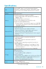
Page 3: ...A series Athlon X4 processors support X8 mode Athlon with Radeon Vega Graphics processors support x4 mode y 2x PCIe 2 0 x1 slots Onboard Graphics y 1x VGA port supports a maximum resolution of 2048x1...

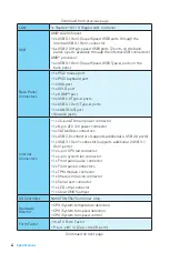
Page 4: ...y 3x audio jacks Internal Connectors y 1x 24 pin ATX main power connector y 1x 8 pin ATX 12V power connector y 4x SATA 6Gb s connectors y 2x USB 2 0 connectors supports additional 4 USB 2 0 ports y 1...

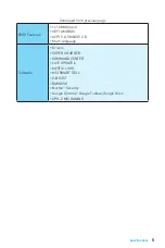
Page 5: ...Mb flash y UEFI AMI BIOS y ACPI 5 0 SM BIOS 2 8 y Multi language Software y Drivers y SUPER CHARGER y COMMAND CENTER y LIVE UPDATE 6 y MYSTIC LIGHT y MSI SMART TOOL y X BOOST y RAMDISK y Norton Secur...

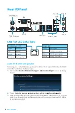
Page 6: ...you have to connect front audio I O module to JAUD1 connector and follow the below steps 1 Click on the Realtek HD Audio Manager Advanced Settings to open the dialog below 2 Select Mute the rear outpu...

Page 7: ...ents BAT1 CPU_FAN1 CPU Socket SYS_FAN1 PCI_E3 JAUD1 JTPM1 PCI_E2 PCI_E1 DIMMA1 DIMMB1 JBAT1 JCI1 JFP2 SATA2 SATA1 ATX_PWR1 CPU_PWR1 EZ Debug LED SATA3 M2_1 SATA4 JUSB1 JUSB3 JUSB2 JLED1 JFP1 JCOM1 Ove...

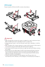
Page 8: ...heatsink is necessary to prevent overheating and maintain system stability y Confirm that the CPU heatsink has formed a tight seal with the CPU before booting your system y Overheating can seriously...

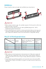
Page 9: ...ion on compatible memory PCI_E1 3 PCIe Expansion Slots Important y When adding or removing expansion cards always turn off the power supply and unplug the power supply power cable from the power outle...

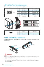
Page 10: ...ntical plugs on either sides of the cable However it is recommended that the flat connector be connected to the motherboard for space saving purposes JFP1 JFP2 Front Panel Connectors These connectors...

Page 11: ...Ground 7 Ground 19 Ground 8 PWR OK 20 Res 9 5VSB 21 5V 10 12V 22 5V 11 12V 23 5V 12 3 3V 24 Ground 5 4 1 8 CPU_PWR1 1 Ground 5 12V 2 Ground 6 12V 3 Ground 7 12V 4 Ground 8 12V Important Make sure that...

Page 12: ...RX_DN 9 USB2 0 19 Power 10 NC 20 No Pin Important Note that the Power and Ground pins must be connected correctly to avoid possible damage JUSB1 2 USB 2 0 Connectors These connectors allow you to conn...

Page 13: ...nstruction below to adjust the fan connector to PWM or DC Mode Switching fan mode and adjusting fan speed You can switch between PWM mode and DC mode and adjust fan speed in BIOS HARDWARE MONITOR Sele...

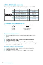
Page 14: ...switch cable Normal default Trigger the chassis intrusion event Using chassis intrusion detector 1 Connect the JCI1 connector to the chassis intrusion switch sensor on the chassis 2 Close the chassis...

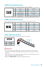
Page 15: ...DCD 2 SIN 3 SOUT 4 DTR 5 Ground 6 DSR 7 RTS 8 CTS 9 RI 10 No Pin JLED1 LED strip connector This connector allows you to connect the single color LED strip Important y This connector supports 5050 sing...

Page 16: ...OS Reset BIOS Resetting BIOS to default values 1 Power off the computer and unplug the power cord 2 Use a jumper cap to short JBAT1 for about 5 10 seconds 3 Remove the jumper cap from JBAT1 4 Plug the...

Page 17: ...ly and may vary from the product you purchased y The BIOS items will vary with the processor Entering BIOS Setup Press Delete key when the Press DEL key to enter Setup Menu F11 to enter Boot Menu mess...

Page 18: ...Insert the USB flash drive that contains the update file into the computer 3 Select the M FLASH tab and click on Yes to reboot the system and enter the flash mode 4 Select a BIOS file to perform the B...

Page 19: ...5 Select your optical drive from the Boot Menu 6 Press any key when screen shows Press any key to boot from CD or DVD message 7 Follow the instructions on the screen to install Windows 10 Installing D...

Page 20: ...Driver Disc into your optical drive 2 The installer will automatically appear 3 Click Utilities tab 4 Select the utilities you want to install 5 Click Install button 6 The utilities installation will...

Page 21: ...10 ATX_PWR1 CPU_PWR1 11 M2_1 M 2 Key M 11 JUSB1 2 USB 2 0 12 JUSB3 USB 3 1 Gen1 12 CPU_FAN1 SYS_FAN1 13 JTPM1 TPM 14 JCI1 14 JAUD1 15 JCOM1 15 JLED1 LED 15 JBAT1 CMOS Reset BIOS 16 EZ LED LED 16 BIOS...

Page 22: ...2 y ESD y y y ESD ESD y y y y y y y y PSU PSU y y y y 60 C 140 F...

Page 23: ...Athlon X4 2400 MHz www msi com y PCIe 3 0 x16 1 Ryzen x16 Radeon Ryzen A Athlon X4 x8 Radeon Athlon x4 y PCIe 2 0 x1 2 y VGA 1 2048x1280 60Hz y DVI D 1 1920x1200 60Hz y HDMI 1 4 1 4096x2160 24Hz Rade...

Page 24: ...B 6 2 USB 4 AMD y USB 3 1 Gen1 USB A 4 y PS 2 1 y PS 2 1 y USB 2 0 A 2 y VGA 1 y DVI D 1 y HDMI 1 y USB 3 1 Gen1 A 4 y LAN RJ45 1 y 3 y 24 ATX 1 y 8 ATX 12V 1 y SATA 6Gb s 4 y USB 2 0 2 USB 2 0 4 y US...

Page 25: ...5 y m ATX y 9 6 in x 8 1 in 24 4 cm x 20 6 cm BIOS y 128 Mb 1 y UEFI AMI BIOS y ACPI 5 0 SM BIOS 2 8 y y y SUPER CHARGER y y 6 y y MSI y X y y y y CPU Z MSI...

Page 26: ...D1 1 Realtek HD Audio Manager Realtek HD Advanced Settings 2 Mute the rear output device when a front headphone plugged in 3 I O PS 2 Mouse PS 2 Keyboard LAN USB 3 1 Gen1 USB 2 0 DVI D VGA LED LAN LAN...

Page 27: ...7 BAT1 CPU_FAN1 CPU SYS_FAN1 PCI_E3 JAUD1 JTPM1 PCI_E2 PCI_E1 DIMMA1 DIMMB1 JBAT1 JCI1 JFP2 SATA2 SATA1 ATX_PWR1 CPU_PWR1 EZ LED SATA3 M2_1 SATA4 JUSB1 JUSB3 JUSB2 JLED1 JFP1 JCOM1...

Page 28: ...8 CPU CPU CPU y AM4 BIOS y CPU y CPU CPU CPU y CPU y CPU CPU CPU y CPU 1 3 5 4 6 7 8 2...

Page 29: ...i com PCI_E1 3 PCIe y y MSI Gaming Series Graphics Card Bolster 1 1 2 3 3 2 RYZEN Radeon Ryzen A Athlon X4 Radeon Athlon PCI_E1 PCIe 3 0 x16 PCIe 3 0 x8 PCIe 3 0 x4 PCI_E2 PCIe 2 0 x1 PCIe 2 0 x1 PCIe...

Page 30: ...JFP1 JFP2 LED 1 2 10 9 JFP1 1 HDD LED 2 Power LED 3 HDD LED 4 Power LED 5 Reset Switch 6 Power Switch 7 Reset Switch 8 Power Switch 9 Reserved 10 No Pin 1 JFP2 1 Speaker 2 Buzzer 3 Buzzer 4 Speaker H...

Page 31: ...Ground 15 Ground 4 5V 16 PS ON 5 Ground 17 Ground 6 5V 18 Ground 7 Ground 19 Ground 8 PWR OK 20 Res 9 5VSB 21 5V 10 12V 22 5V 11 12V 23 5V 12 3 3V 24 Ground 5 4 1 8 CPU_PWR1 1 Ground 5 12V 2 Ground 6...

Page 32: ...Ground 14 USB3_TX_C_DP 5 USB3_TX_C_DN 15 USB3_TX_C_DN 6 USB3_TX_C_DP 16 Ground 7 Ground 17 USB3_RX_DP 8 USB2 0 18 USB3_RX_DN 9 USB2 0 19 Power 10 NC 20 No Pin JUSB1 2 USB 2 0 USB 2 0 1 2 10 9 1 VCC 2...

Page 33: ...se Width Modulation DC PWM 12V DC PWM 3 Non PWM 100 PWM DC PWM DC BIOS HARDWARE MONITOR PWM DC PWM DC CPU PWM DC 1 CPU_FAN1 1 SYS_FAN1 PWM 1 Ground 2 12V 3 Sense 4 Speed Control Signal DC 1 Ground 2 V...

Page 34: ...RQ 7 LPC address data pin1 8 5V Power 9 LPC address data pin2 10 No Pin 11 LPC address data pin3 12 Ground 13 LPC Frame 14 Ground JCI1 1 JCI1 2 3 BIOS SETTINGS Security Chassis Intrusion Configuration...

Page 35: ...MIC Detection 7 SENSE_SEND 8 No Pin 9 Head Phone L 10 Head Phone Detection JCOM1 1 2 10 9 1 DCD 2 SIN 3 SOUT 4 DTR 5 Ground 6 DSR 7 RTS 8 CTS 9 RI 10 No Pin JLED1 LED LED y 3A 12V 5050 LED LED 2m y LE...

Page 36: ...16 JBAT1 CMOS Reset BIOS CMOS CMOS CMOS BIOS BIOS 1 2 JBAT1 5 10 3 JBAT1 4 EZ LED LED LED CPU CPU DRAM DRAM VGA GPU BOOT...

Page 37: ...7 BIOS BIOS BIOS y BIOS BIOS BIOS HELP y y BIOS BIOS Press DEL key to enter Setup Menu F11 to enter Boot Menu DEL F11 Delete F1 F2 F3 F4 CPU F5 Memory Z F6 F7 EZ F8 F9 F10 F12 USB FAT FAT32 F10 Yes No...

Page 38: ...OS BIOS CMOS BIOS M FLASH BIOS BIOS MSI BIOS USB BIOS 1 POST Del BIOS 2 USB 3 M FLASH Yes 4 BIOS BIOS 5 100 Live Update 6 BIOS LAN BIOS 1 MSI LIVE UPDATE 6 2 BIOS Update 3 Scan 4 Download BIOS 5 Next...

Page 39: ...msi com Windows Windows 10 64 1 2 Windows 10 3 Restart 4 POST Power On Self Test F11 5 6 Press any key to boot from CD or DVD 7 Windows 7 10 1 Start up your computer in Windows 10 2 MSI 3 4 Install 5...

Page 40: ...20 1 MSI 2 3 Utilities 4 5 Install 6 7 OK 8...

Page 41: ...ventilateurs 13 JTPM1 Connecteur de module TPM 14 JCI1 Connecteur intrusion ch ssis 14 JAUD1 Connecteur audio avant 15 JCOM1 Connecteur de port s rie 15 JLED1 Connecteur de ruban LED 15 JBAT1 Cavalie...

Page 42: ...ien fix s sur la carte m re ou ailleurs dans le bo tier de l ordinateur y Ne d marrez pas l ordinateur avant d avoir termin l installation Ceci peut endommager les composants ou vous blesser y Si vous...

Page 43: ...moire compatible Slots d extension y 1 x slot PCIe 3 0 x16 Les processeurs de s rie Ryzen supportent mode x16 Les processeurs Ryzen avec processeur graphique Radeon Vega et processeur de s rie A Athl...

Page 44: ...tion 7 1 LAN 1 x contr leur Realtek 8111H Gigabit LAN USB Chipset AMD A320 y 2 x ports USB 3 1 Gen1 SuperSpeed USB par l interm diaire du connecteur USB 3 1 Gen1 interne y 6 x ports USB 2 0 High speed...

Page 45: ...r de module TPM y 1 x connecteur intrusion ch ssis y 1 x connecteur de port s rie y 1 x connecteur de ruban LED y 1 x cavalier Clear CMOS Contr leur E S Contr leur NUVOTON 5567 Moniteur syst me y D te...

Page 46: ...au connecteur JAUD1 et suivez les tapes ci dessous 1 Cliquez sur Realtek HD Audio Manager Advanced Settings Param tres avanc s pour ouvrir le dialogue suivant 2 Choisissez Mute the rear output device...

Page 47: ...s BAT1 CPU_FAN1 Socket processeur SYS_FAN1 PCI_E3 JAUD1 JTPM1 PCI_E2 PCI_E1 DIMMA1 DIMMB1 JBAT1 JCI1 JFP2 SATA2 SATA1 ATX_PWR1 CPU_PWR1 EZ Debug LED SATA3 M2_1 SATA4 JUSB1 JUSB3 JUSB2 JLED1 JFP1 JCOM1...

Page 48: ...eur est n cessaire pour prot ger le processeur contre la surchauffe et maintenir la stabilit du syst me y Assurez vous de l tanch it entre le ventilateur et le processeur avant de d marrer votre syst...

Page 49: ...s r f rer au site www msi com pour plus d informations sur la m moire compatible PCI_E1 3 Slots d extension PCIe Important y Veillez toujours mettre l ordinateur hors tension et d brancher le cordon d...

Page 50: ...SATA dispose de prises identiques sur chaque c t N anmoins il est recommand de connecter la prise plate sur la carte m re pour un gain d espace JFP1 JFP2 Connecteurs de panneau avant Ces connecteurs s...

Page 51: ...5V 18 Ground 7 Ground 19 Ground 8 PWR OK 20 Res 9 5VSB 21 5V 10 12V 22 5V 11 12V 23 5V 12 3 3V 24 Ground 5 4 1 8 CPU_PWR1 1 Ground 5 12V 2 Ground 6 12V 3 Ground 7 12V 4 Ground 8 12V Important Veuille...

Page 52: ...in Important Notez que les c bles d alimentation et de terre doivent tre branch s correctement afin d viter d endommager la carte JUSB1 2 Connecteurs USB 2 0 Ces connecteurs vous permettent de relier...

Page 53: ...de ventilateur en mode PWM ou mode DC Basculer entre les modes des ventilateurs et ajuster la vitesse Vous pouvez alterner entre le mode PWM et le mode DC et ajuster la vitesse des ventilateurs dans l...

Page 54: ...interrupteur ou au capteur d intrusion ch ssis situ sur le bo tier du PC 2 Fermez le couvercle du bo tier 3 Allez dans le BIOS SETTINGS R glages Security S curit Chassis Intrusion Configuration Config...

Page 55: ...10 No Pin JLED1 Connecteur de ruban LED Ce connecteur vous permet de connecter le ruban LED unicolore Important y Ce connecteur supporte un ruban LED unicolore de type 5050 avec une puissance nominale...

Page 56: ...ordinateur et d branchez le c ble d alimentation de la prise lectrique 2 Utilisez un couvercle de cavalier pour fermer JBAT1 pour environ 5 10 secondes 3 Enlevez le couvercle de cavalier du JBAT1 4 B...

Page 57: ...vous achetez y Les l ments du BIOS peuvent varier selon le processeur Entrer dans l interface Setup du BIOS Pendant le d marrage lorsqu appara t le message Press DEL key to enter Setup Menu F11 to en...

Page 58: ...r dans l interface Setup du BIOS pendant le processus de POST 2 Connectez le lecteur Flash USB contenant le profil l ordinateur 3 Choisissez l onglet M FLASH et cliquez sur Yes Oui pour red marrer le...

Page 59: ...Boot Menu 5 Choisissez le lecteur optique du Boot Menu 6 Appuyez sur n importe quelle touche lorsqu appara t le message Press any key to boot from CD or DVD 7 Suivez les instructions l cran pour insta...

Page 60: ...er Disc dans le lecteur optique 2 L outil d installation appara t automatiquement 3 Cliquez sur l onglet Utilities 4 Choisissez les utilitaires que vous voulez installer 5 Cliquez sur le bouton Instal...

Page 61: ...ter 13 JTPM1 TPM Anschluss 14 JCI1 Geh usekontaktanschluss 14 JAUD1 Audioanschluss des Frontpanels 15 JCOM1 Serieller Anschluss 15 JLED1 RGB LED Streifen Anschluss 15 JBAT1 Clear CMOS Steckbr cke Rese...

Page 62: ...er nicht bevor die Installation abgeschlossen ist Dies k nnte permanente Sch den an den Komponenten sowie zu das Verletzung des Benutzers verursachen y Sollten Sie Hilfe bei der Installation ben tigen...

Page 63: ...ng anschl sse y 1x PCIe 3 0 x16 Steckplatz Ryzen Serie Prozessoren unterst tzen den Modus x16 Ryzen Prozessoren mit Radeon Vega Grafikprozessor und A Serie Athlon X4 Prozessoren unterst tzen den Modus...

Page 64: ...ler USB AMD A320 Chipsatz y 2x USB 3 1 Gen1 SuperSpeed USB Anschl sse stehen durch die internen USB 3 1 Gen1 Anschl sse zur Verf gung y 6x USB 2 0 High speed USB Anschl sse 2 Anschl sse an der r cksei...

Page 65: ...M Anschluss y 1x Geh usekontaktschalter y 1x Serieller Anschluss y 1x LED Streifen Anschluss y 1x Clear CMOS Steckbr cke E A Anschluss NUVOTON 5567 Controller Chip Hardware Monitor y CPU System Temper...

Page 66: ...schluss verbinden und folgen Sie die untenstehenden Schritten 1 Klicken Sie auf Realtek HD Audio Manager Advanced Settings um das Dialogfeld zu ffnen 2 W hlen Sie Mute the rear output device die r cks...

Page 67: ...nten BAT1 CPU_FAN1 CPU Sockel SYS_FAN1 PCI_E3 JAUD1 JTPM1 PCI_E2 PCI_E1 DIMMA1 DIMMB1 JBAT1 JCI1 JFP2 SATA2 SATA1 ATX_PWR1 CPU_PWR1 EZ Debug LED SATA3 M2_1 SATA4 JUSB1 JUSB3 JUSB2 JLED1 JFP1 JCOM1 ber...

Page 68: ...itzung zu vermeiden und die Systemstabilit t beizubehalten y Stellen Sie sicher dass Ihr K hlk rper eine feste Verbindung mit der CPU hergestellt hat bevor Sie Ihr System starten y berhitzung besch di...

Page 69: ...ttp www msi com PCI_E1 3 PCIe Erweiterungssteckpl tze Wichtig y Achten Sie darauf dass Sie den Strom abschalten und das Netzkabel aus der Steckdose herausziehen bevor Sie eine Erweiterungskarte instal...

Page 70: ...die Folge sein y SATA Kabel haben identische Stecker an beiden Enden Es wird empfohlen den flachen Stecker auf dem Motherboard einstecken JFP1 JFP2 Frontpanel Anschl sse Diese Anschl sse verbinden die...

Page 71: ...Ground 19 Ground 8 PWR OK 20 Res 9 5VSB 21 5V 10 12V 22 5V 11 12V 23 5V 12 3 3V 24 Ground 5 4 1 8 CPU_PWR1 1 Ground 5 12V 2 Ground 6 12V 3 Ground 7 12V 4 Ground 8 12V Wichtig Make sure that all the p...

Page 72: ...s Sie die mit Stromf hrende Leitung und Erdleitung bezeichneten Pins korrekt verbinden m ssen ansonsten kann es zu Sch den kommen JUSB1 2 USB 2 0 Anschl sse Mit diesen Anschl ssen k nnen Sie die USB 2...

Page 73: ...e den folgenden Anweisungen um den PWM oder DC Modus auszuw hlen Umschalten des L fter Modus und Anpassung der L fterdrehzahl You can switch between PWM mode and DC mode and adjust fan speed in BIOS H...

Page 74: ...L se den Geh useeingriff aus Geh usekontakt Detektor verwenden 1 Schlie en Sie den JCI1 Anschluss am Geh usekontakt Schalter Sensor am Geh use an 2 Schlie en Sie die Geh useabdeckung 3 Gehen Sie zu BI...

Page 75: ...d 6 DSR 7 RTS 8 CTS 9 RI 10 No Pin JLED1 RGB LED Streifen Anschluss Mit diesem Anschluss k nnen Sie den einfarbigen LED Streifen anschlie en Wichtig y Dieser Anschluss unterst tzt die 5050 RGB einfarb...

Page 76: ...des R cksetzen des BIOS auf Standardwerte 1 Schalten Sie den Computer ab und ziehen Sie das Netzkabel ab 2 Verwenden Sie eine Steckbr cke um JBAT1 f r 5 10 Sekunden kurzzuschlie en 3 Entfernen Sie die...

Page 77: ...benen Produkt abweichen y Die BIOS Funktion variiert je nach dem Prozessor ffnen des BIOS Setups W hrend des BOOT Vorgangs dr cken Sie die Taste Delete wenn die Meldung Press DEL key to enter Setup Me...

Page 78: ...hlie en das USB Flashlaufwerk mit der BIOS Datei an den Computer 3 W hlen Sie die Registerkarte M FLASH und klicken Sie auf Yes Ja um das System neu zu starten Rufen Sie den Flash Modus auf 4 W hlen S...

Page 79: ...6 Wenn eine entsprechende Meldung Press any key to boot from CD or DVD angezeigt wird dr cken Sie eine beliebige Taste 7 Folgen Sie den Anweisungen auf dem Bildschirm um das Dienstprogramm Windows 10...

Page 80: ...optisches Laufwerk 2 Der Installer wird automatisch erscheint 3 Klicken Sie auf Utilities 4 W hlen Sie die Dienstprogramme die installiert werden soll 5 Klicken Sie die Taste Install 6 Die Utilities...

Page 81: ...6 10 ATX_PWR1 CPU_PWR1 11 M2_1 M 2 M 11 JUSB1 2 USB 2 0 12 JUSB3 USB 3 1 Gen1 12 CPU_FAN1 SYS_FAN1 13 JTPM1 14 JCI1 14 JAUD1 15 JCOM1 15 JLED1 LED 15 JBAT1 CMOS BIOS 16 EZ Debug LED 16 BIOS 17 BIOS 17...

Page 82: ...2 y y y y y y y y y y y y y y y y 60 C 140 F...

Page 83: ...00 2667 OC 2933 OC 3200 OC y y ECC UDIMM non ECC y non ECC UDIMM A Athlon X4 2400 www msi com y 1x PCIe 3 0 x16 Ryzen x16 Ryzen Radeon Vega A Athlon X4 x8 Athlon Radeon Vega x4 y 2x PCIe 2 0 x1 y 1x V...

Page 84: ...0 2280 y Realtek ALC887 Codec y 7 1 High Definition Audio LAN 1x Realtek 8111H USB AMD A320 y 2x USB 3 1 Gen1 SuperSpeed USB USB 3 1 Gen1 y 6x USB 2 0 High speed USB 2 4 USB AMD y 4x USB 3 1 Gen1 Supe...

Page 85: ...1x y 1x y 1x LED y 1x CMOS NUVOTON 5567 y CPU y CPU y CPU y m ATX y 9 6 x 8 1 24 4 x 20 6 BIOS y 1x 128 y UEFI AMI BIOS y ACPI 5 0 SM BIOS 2 8 y y y SUPER CHARGER y COMMAND CENTER y LIVE UPDATE 6 y M...

Page 86: ...AN Audio 7 1 7 1 JAUD1 1 Realtek HD Audio Manager Advanced Settings 2 Mute the rear output device when a front headphone plugged in 3 10 100 1 PS 2 Keyboard PS 2 Mouse LAN USB 3 1 Gen1 USB 2 0 DVI D V...

Page 87: ...7 BAT1 CPU_FAN1 SYS_FAN1 PCI_E3 JAUD1 JTPM1 PCI_E2 PCI_E1 DIMMA1 DIMMB1 JBAT1 JCI1 JFP2 SATA2 SATA1 ATX_PWR1 CPU_PWR1 EZ Debug LED SATA3 M2_1 SATA4 JUSB1 JUSB3 JUSB2 JLED1 JFP1 JCOM1...

Page 88: ...8 y 4 BIOS y y y y y 1 3 5 4 6 7 8 2...

Page 89: ...3 PCIe y y MSI Gaming Series Graphics Card Bolster 1 1 2 3 3 2 RYZEN Ryzen Radeon Vega A Athlon X4 Athlon Radeon Vega PCI_E1 PCIe 3 0 x16 PCIe 3 0 x8 PCIe 3 0 x4 PCI_E2 PCIe 2 0 x1 PCIe 2 0 x1 PCIe 2...

Page 90: ...P1 JFP2 1 2 10 9 JFP1 1 HDD LED 2 Power LED 3 HDD LED 4 Power LED 5 Reset Switch 6 Power Switch 7 Reset Switch 8 Power Switch 9 Reserved 10 No Pin 1 JFP2 1 Speaker 2 Buzzer 3 Buzzer 4 Speaker HDD LED...

Page 91: ...V 3 Ground 15 Ground 4 5V 16 PS ON 5 Ground 17 Ground 6 5V 18 Ground 7 Ground 19 Ground 8 PWR OK 20 Res 9 5VSB 21 5V 10 12V 22 5V 11 12V 23 5V 12 3 3V 24 Ground 5 4 1 8 CPU_PWR1 1 Ground 5 12V 2 Groun...

Page 92: ...Ground 14 USB3_TX_C_DP 5 USB3_TX_C_DN 15 USB3_TX_C_DN 6 USB3_TX_C_DP 16 Ground 7 Ground 17 USB3_RX_DP 8 USB2 0 18 USB3_RX_DN 9 USB2 0 19 Power 10 NC 20 No Pin JUSB1 2 USB 2 0 USB 2 0 1 2 10 9 1 VCC 2...

Page 93: ...N1 PWM PulseWidth Modulation PWM 12 3 Non PWM PWM PWM DC BIOS HARDWARE MONITOR PWM DC PWM DC PWM DC PWM 1 CPU_FAN1 1 SYS_FAN1 PWM 1 Ground 2 12V 3 Sense 4 Speed Control Signal DC 1 Ground 2 Voltage Co...

Page 94: ...PC address data pin1 8 5V Power 9 LPC address data pin2 10 No Pin 11 LPC address data pin3 12 Ground 13 LPC Frame 14 Ground JCI1 1 JCI1 2 3 BIOS SETTINGS Security Chassis Intrusion Configuration 4 Cha...

Page 95: ...Phone R 6 MIC Detection 7 SENSE_SEND 8 No Pin 9 Head Phone L 10 Head Phone Detection JCOM1 1 2 10 9 1 DCD 2 SIN 3 SOUT 4 DTR 5 Ground 6 DSR 7 RTS 8 CTS 9 RI 10 No Pin JLED1 LED y 5050 3 12 2 y RGB y M...

Page 96: ...16 JBAT1 CMOS BIOS CMOS CMOS BIOS BIOS 1 2 JBAT1 5 10 3 JBAT1 4 EZ Debug LED CPU DRAM DRAM VGA BOOT...

Page 97: ...17 BIOS BIOS BIOS y BIOS BIOS BIOS HELP y y BIOS BIOS Delete Press DEL key to enter Setup Menu F11 to enter Boot Menu F1 F2 F3 F4 F5 Memory Z F6 F7 EZ F8 F9 F10 F12 USB FAT FAT32 F10 Yes No...

Page 98: ...CMOS BIOS CMOS BIOS BIOS M FLASH BIOS MSI BIOS USB BIOS 1 Del BIOS POST 2 USB 3 M FLASH Yes 4 BIOS BIOS 5 BIOS Live Update 6 BIOS 1 MSI LIVE UPDATE 6 2 BIOS Update 3 Scan 4 Download BIOS 5 Next In Wi...

Page 99: ...19 C www msi com Windows 10 64 1 2 Windows 10 3 Restart 4 F11 POST Power On Self Test 5 6 Press any key to boot from CD or DVD 7 Windows 10 1 Windows 10 2 MSI Driver Disc 3 4 Install 5 6 OK 7...

Page 100: ...20 1 MSI Driver Disc 2 3 Utilities 4 5 Install 6 7 OK 8...

Page 101: ...b s 10 ATX_PWR1 CPU_PWR1 11 M2_1 M 2 M 11 JUSB1 2 USB 2 0 12 JUSB3 USB 3 1 Gen1 12 CPU_FAN1 SYS_FAN1 13 JTPM1 TPM 14 JCI1 14 JAUD1 15 JCOM1 15 JLED1 LED 15 JBAT1 CMOS BIOS 16 EZ Debug LED LED 16 BIOS...

Page 102: ...2 y ESD y y y ESD ESD y y y y y y y y y y y y 60 140...

Page 103: ...x16 x16 Radeon Vega Graphics A series Athlon X4 x8 Radeon Vega Graphics Athlon x4 y 2 PCIe 2 0 x1 y 1 VGA 2048x1280 60Hz y 1 DVI D 1920x1200 60Hz y 1 HDMI 1 4 4096x2160 24Hz Radeon Vega Graphics Rade...

Page 104: ...peed USB Type A y 1 PS 2 y 1 PS 2 y 2 USB 2 0 Type A y 1 VGA y 1 DVI D y 1 HDMI y 4 USB 3 1 Gen1 Type A y 1 LAN RJ45 y 3 y 1 24 pin ATX y 1 8 pin ATX 12V y 4 SATA 6Gb s y 2 USB 2 0 4 USB 2 0 y 1 USB 3...

Page 105: ...5 y m ATX y 9 6 x 8 1 24 4 x 20 6 BIOS y 1 128 Mb flash y UEFI AMI BIOS y ACPI 5 0 SM BIOS 2 8 y y y y COMMAND CENTER y LIVE UPDATE 6 y RGB LED y MSI y y y y Google Google Google y MSI GAMING CPU Z...

Page 106: ...10 Mbps 100 Mbps 1 Gbps LAN LED 7 1 7 1 I O JAUD1 1 Realtek HD Audio Manager Advanced Settings 2 Mute the rear output device when a front headphone plugged in 3 I O PS 2 PS 2 LAN USB 3 1 Gen1 USB 2 0...

Page 107: ...7 BAT1 CPU_FAN1 CPU SYS_FAN1 PCI_E3 JAUD1 JTPM1 PCI_E2 PCI_E1 DIMMA1 DIMMB1 JBAT1 JCI1 JFP2 SATA2 SATA1 ATX_PWR1 CPU_PWR1 EZ Debug LED SATA3 M2_1 SATA4 JUSB1 JUSB3 JUSB2 JLED1 JFP1 JCOM1...

Page 108: ...8 CPU CPU CPU y AM4 BIOS y CPU y CPU CPU CPU y CPU CPU y CPU CPU CPU y CPU 1 3 5 4 6 7 8 2...

Page 109: ...i com PCI_E1 3 PCIe y y MSI 1 1 2 3 3 2 Radeon Vega Graphics A series Athlon X4 Radeon Vega Graphics Athlon PCI_E1 PCIe 3 0 x16 PCIe 3 0 x8 PCIe 3 0 x4 PCI_E2 PCIe 2 0 x1 PCIe 2 0 x1 PCIe 2 0 x1 PCI_E...

Page 110: ...JFP1 JFP2 LED 1 2 10 9 JFP1 1 HDD LED 2 Power LED 3 HDD LED 4 Power LED 5 Reset Switch 6 Power Switch 7 Reset Switch 8 Power Switch 9 Reserved 10 No Pin 1 JFP2 1 Speaker 2 Buzzer 3 Buzzer 4 Speaker H...

Page 111: ...3 Ground 15 Ground 4 5V 16 PS ON 5 Ground 17 Ground 6 5V 18 Ground 7 Ground 19 Ground 8 PWR OK 20 Res 9 5VSB 21 5V 10 12V 22 5V 11 12V 23 5V 12 3 3V 24 Ground 5 4 1 8 CPU_PWR1 1 Ground 5 12V 2 Ground...

Page 112: ...Ground 14 USB3_TX_C_DP 5 USB3_TX_C_DN 15 USB3_TX_C_DN 6 USB3_TX_C_DP 16 Ground 7 Ground 17 USB3_RX_DP 8 USB2 0 18 USB3_RX_DN 9 USB2 0 19 Power 10 NC 20 No Pin JUSB1 2 USB 2 0 USB 2 0 1 2 10 9 1 VCC 2...

Page 113: ...S_FAN1 PWM DC PWM 12V DC 3 PWM PWM 100 PWM DC PWM DC BIOS HARDWARE MONITOR PWM DC PWM DC CPU PWM DC 1 CPU_FAN1 1 SYS_FAN1 PWM 1 Ground 2 12V 3 Sense 4 Speed Control Signal DC 1 Ground 2 Voltage Contro...

Page 114: ...ress data pin1 8 5V Power 9 LPC address data pin2 10 No Pin 11 LPC address data pin3 12 Ground 13 LPC Frame 14 Ground JCI1 1 JCI1 2 3 BIOS SETTINGS Security Chassis Intrusion Configuration 4 Chassis I...

Page 115: ...MIC Detection 7 SENSE_SEND 8 No Pin 9 Head Phone L 10 Head Phone Detection JCOM1 1 2 10 9 1 DCD 2 SIN 3 SOUT 4 DTR 5 Ground 6 DSR 7 RTS 8 CTS 9 RI 10 No Pin JLED1 LED LED y 5050 LED 3A 12V LED 2 y LE...

Page 116: ...16 JBAT1 CMOS BIOS CMOS CMOS CMOS BIOS BIOS 1 2 JBAT1 5 10 3 JBAT1 4 EZ Debug LED LED LED CPU CPU DRAM DRAM VGA GPU BOOT...

Page 117: ...17 BIOS BIOS BIOS y BIOS BIOS y y BIOS BIOS Press DEL key to enter Setup Menu F11 to enter Boot Menu Delete F1 F2 F3 Favorites F4 CPU F5 Memory Z F6 F7 EZ F8 F9 F10 F12 U FAT FAT32 F10 Yes No...

Page 118: ...S CMOS BIOS BIOS M FLASH BIOS MSI BIOS BIOS U BIOS 1 POST Del BIOS 2 U 3 M FLASH Yes flash 4 BIOS BIOS 5 100 Live Update 6 BIOS LAN BIOS 1 MSI LIVE UPDATE 6 2 BIOS Update 3 Scan 4 Download BIOS 5 Next...

Page 119: ...19 www msi com Windows 10 64 bit 1 2 Windows 10 3 Restart 4 POST F11 5 6 Press any key to boot from CD or DVD 7 Windows 10 1 Windows 10 2 MSI 3 4 Install 5 6 OK 7...

Page 120: ...20 1 MSI 2 3 Utilities 4 5 Install 6 7 OK 8...

Page 121: ...PWR1 CPU_PWR1 11 M2_1 M 2 M Key 11 JUSB1 2 USB 2 0 12 JUSB3 USB 3 1 Gen1 12 CPU_FAN1 SYS_FAN1 13 JTPM1 TPM 14 JCI1 14 JAUD1 15 JCOM1 15 JLED1 LED 15 JBAT1 CMOS BIOS 16 EZ Debug LED LED 16 BIOS 17 BIOS...

Page 122: ...2 y ESD y y y y y y y y y y y y y y y 60 C 140 F...

Page 123: ...Ie 3 0 x16 Ryzen x16 Radeon Vega Ryzen A Athlon X4 x8 Radeon Vega Athlon x4 y 2 PCIe 2 0 x1 y 1 VGA 2048x1280 60Hz y 1 DVI D 1920x1200 60Hz y 1 HDMI 1 4 4096x2160 24Hz Radeon Vega Ryzen Radeon Vega At...

Page 124: ...e A y 1 PS 2 y 1 PS 2 y 2 USB 2 0 Type A y 1 VGA y 1 DVI D y 1 HDMI y 4 USB 3 1 Gen1 Type A y 1 LAN RJ45 y 3 y 1 24 pin ATX y 1 8 pin ATX 12V y 4 SATA 6Gb s y 2 USB 2 0 4 USB 2 0 y 1 USB 3 1 Gen1 2 US...

Page 125: ...flash y UEFI AMI BIOS y ACPI 5 0 SM BIOS 2 8 y y y SUPER CHARGER y COMMAND CENTER y LIVE UPDATE 6 y MYSTIC LIGHT y MSI SMART TOOL y X BOOST y RAMDISK y Norton Security y Google Chrome Google Google y...

Page 126: ...I O 10 Mbps 100 Mbps 1 Gbps LED 7 1 7 1 I O JAUD1 1 Realtek HD Audio Manager Advanced Settings 2 Mute the rear output device when a front headphone plugged in 3 I O PS 2 PS 2 USB 3 1 Gen1 USB 2 0 DVI...

Page 127: ...7 BAT1 CPU_FAN1 CPU SYS_FAN1 PCI_E3 JAUD1 JTPM1 PCI_E2 PCI_E1 DIMMA1 DIMMB1 JBAT1 JCI1 JFP2 SATA2 SATA1 ATX_PWR1 CPU_PWR1 EZ Debug LED SATA3 M2_1 SATA4 JUSB1 JUSB3 JUSB2 JLED1 JFP1 JCOM1...

Page 128: ...8 CPU CPU CPU y AM4 BIOS y y CPU CPU y CPU y CPU CPU CPU y CPU 1 3 5 4 6 7 8 2...

Page 129: ...om PCI_E1 3 PCIe y y MSI Gaming Series 1 1 2 3 3 2 RYZEN Radeon Vega Ryzen A Athlon X4 Radeon Vega Athlon PCI_E1 PCIe 3 0 x16 PCIe 3 0 x8 PCIe 3 0 x4 PCI_E2 PCIe 2 0 x1 PCIe 2 0 x1 PCIe 2 0 x1 PCI_E3...

Page 130: ...JFP1 JFP2 LED 1 2 10 9 JFP1 1 HDD LED 2 Power LED 3 HDD LED 4 Power LED 5 Reset Switch 6 Power Switch 7 Reset Switch 8 Power Switch 9 Reserved 10 No Pin 1 JFP2 1 Speaker 2 Buzzer 3 Buzzer 4 Speaker H...

Page 131: ...Ground 15 Ground 4 5V 16 PS ON 5 Ground 17 Ground 6 5V 18 Ground 7 Ground 19 Ground 8 PWR OK 20 Res 9 5VSB 21 5V 10 12V 22 5V 11 12V 23 5V 12 3 3V 24 Ground 5 4 1 8 CPU_PWR1 1 Ground 5 12V 2 Ground 6...

Page 132: ...4 Ground 14 USB3_TX_C_DP 5 USB3_TX_C_DN 15 USB3_TX_C_DN 6 USB3_TX_C_DP 16 Ground 7 Ground 17 USB3_RX_DP 8 USB2 0 18 USB3_RX_DN 9 USB2 0 19 Power 10 NC 20 No Pin JUSB1 2 USB 2 0 USB 2 0 1 2 10 9 1 VCC...

Page 133: ...S_FAN1 PWM DC PWM 12V DC 3 PWM PWM 100 PWM DC PWM DC BIOS HARDWARE MONITOR PWM DC PWM DC CPU PWM DC 1 CPU_FAN1 1 SYS_FAN1 PWM 1 Ground 2 12V 3 Sense 4 Speed Control Signal DC 1 Ground 2 Voltage Contro...

Page 134: ...ress data pin1 8 5V Power 9 LPC address data pin2 10 No Pin 11 LPC address data pin3 12 Ground 13 LPC Frame 14 Ground JCI1 1 JCI1 2 3 BIOS SETTINGS Security Chassis Intrusion Configuration 4 Chassis I...

Page 135: ...Detection 7 SENSE_SEND 8 No Pin 9 Head Phone L 10 Head Phone Detection JCOM1 1 2 10 9 1 DCD 2 SIN 3 SOUT 4 DTR 5 Ground 6 DSR 7 RTS 8 CTS 9 RI 10 No Pin JLED1 LED LED y 5050 LED 3A 12V LED 2 LED y RG...

Page 136: ...16 JBAT1 CMOS BIOS CMOS CMOS CMOS BIOS BIOS 1 2 JBAT1 5 10 3 JBAT1 4 EZ Debug LED LED LED CPU CPU DRAM VGA BOOT...

Page 137: ...17 BIOS BIOS BIOS y BIOS BIOS HELP BIOS y y BIOS BIOS DEL F11 Boot Menu Delete F1 F2 F3 F4 CPU F5 Memory Z F6 F7 EZ F8 F9 F10 F12 USB FAT FAT32 F10...

Page 138: ...MOS CMOS BIOS BIOS M FLASH BIOS MSI BIOS BIOS USB BIOS 1 POST Del BIOS 2 USB 3 M FLASH 4 BIOS BIOS 5 100 Live Update 6 BIOS BIOS 1 MSI LIVE UPDATE 6 2 BIOS Update BIOS 3 Scan 4 Download BIOS 5 Next In...

Page 139: ...19 www msi com Windows Windows 10 64 bit 1 2 Windows 10 3 4 POST F11 5 6 Press any key to boot from CD or DVD 7 Windows 10 1 Windows 10 2 MSI 3 4 5 6 7...

Page 140: ...20 1 MSI 2 3 4 5 6 7 8...

Page 141: ...ATX_PWR1 CPU_PWR1 11 M2_1 M 2 Key M 11 JUSB1 2 USB 2 0 12 JUSB3 USB 3 1 Gen1 12 CPU_FAN1 SYS_FAN1 13 JTPM1 TPM 14 JCI1 14 JAUD1 15 JCOM1 15 JLED1 LED 15 JBAT1 CMOS BIOS 16 EZ Debug LED LED 16 BIOS 17...

Page 142: ...2 y ESD PC y y y ESD ESD y y PC y PC y PC y PC PC y y y y y y PC y 60O C 140O F...

Page 143: ...si com y PCIe 3 0 x16 x1 Ryzen x16 Radeon Vega Ryzen A series Athlon X4 x8 Radeon Vega Athlon x4 y PCIe 2 0 x1 x2 y VGA x1 2048x1280 60Hz y DVI D x1 1920x1200 60Hz y HDMI 1 4 x1 4096x2160 24Hz Radeon...

Page 144: ...pe A x4 y PS 2 x1 y PS 2 x1 y USB 2 0 Type A x2 y VGA x1 y DVI D x1 y HDMI x1 y USB 3 1 Gen1 Type A x4 y LAN RJ45 x1 y x3 y 24 ATX x1 y 8 ATX 12V x1 y SATA 6Gb s x4 y USB 2 0 x2 4 USB 2 0 y USB 3 1 Ge...

Page 145: ...EFI AMI BIOS y ACPI 5 0 SM BIOS 2 8 y y y SUPER CHARGER y COMMAND CENTER y LIVE UPDATE 6 y MYSTIC LIGHT y MSI SMART TOOL y X BOOST y RAMDISK y Norton Security y Google Chrome Google Toolbar Google Dri...

Page 146: ...LED Off 10 Mbps 100 Mbps 1 Gbps LAN LED 7 1 7 1 I O JAUD1 1 Realtek HD Audio Manager Advanced Settings 2 Mute the rear output device when a front headphone plugged in 3 I O PS 2 PS 2 LAN USB 3 1 Gen1...

Page 147: ...7 BAT1 CPU_FAN1 CPU SYS_FAN1 PCI_E3 JAUD1 JTPM1 PCI_E2 PCI_E1 DIMMA1 DIMMB1 JBAT1 JCI1 JFP2 SATA2 SATA1 ATX_PWR1 CPU_PWR1 EZ Debug LED SATA3 M2_1 SATA4 JUSB1 JUSB3 JUSB2 JLED1 JFP1 JCOM1...

Page 148: ...8 CPU CPU CPU y AM4 BIOS y CPU y CPU CPU CPU y CPU CPU y CPU CPU CPU CPU CPU y CPU CPU CPU 1 3 5 4 6 7 8 2...

Page 149: ...CI_E1 3 PCIe y y MSI Gaming Series Graphics Card Bolster 1 1 2 3 3 2 RYZEN Radeon Vega Ryzen A Athlon X4 Radeon Vega Athlon PCI_E1 PCIe 3 0 x16 PCIe 3 0 x8 PCIe 3 0 x4 PCI_E2 PCIe 2 0 x1 PCIe 2 0 x1 P...

Page 150: ...JFP1 JFP2 LED 1 2 10 9 JFP1 1 HDD LED 2 Power LED 3 HDD LED 4 Power LED 5 Reset Switch 6 Power Switch 7 Reset Switch 8 Power Switch 9 Reserved 10 No Pin 1 JFP2 1 Speaker 2 Buzzer 3 Buzzer 4 Speaker H...

Page 151: ...Ground 15 Ground 4 5V 16 PS ON 5 Ground 17 Ground 6 5V 18 Ground 7 Ground 19 Ground 8 PWR OK 20 Res 9 5VSB 21 5V 10 12V 22 5V 11 12V 23 5V 12 3 3V 24 Ground 5 4 1 8 CPU_PWR1 1 Ground 5 12V 2 Ground 6...

Page 152: ...Ground 14 USB3_TX_C_DP 5 USB3_TX_C_DN 15 USB3_TX_C_DN 6 USB3_TX_C_DP 16 Ground 7 Ground 17 USB3_RX_DP 8 USB2 0 18 USB3_RX_DN 9 USB2 0 19 Power 10 NC 20 No Pin JUSB1 2 USB 2 0 USB 2 0 1 2 10 9 1 VCC 2...

Page 153: ...FAN1 PWM DC PWM 12V DC 3 Non PWM PWM 100 PWM DC BIOS HARDWARE MONITOR PWM DC PWM DC PWM DC CPU PWM DC 1 CPU_FAN1 1 SYS_FAN1 PWM 1 Ground 2 12V 3 Sense 4 Speed Control Signal DC 1 Ground 2 Voltage Cont...

Page 154: ...RQ 7 LPC address data pin1 8 5V Power 9 LPC address data pin2 10 No Pin 11 LPC address data pin3 12 Ground 13 LPC Frame 14 Ground JCI1 1 JCI1 2 3 BIOS SETTINGS Security Chassis Intrusion Configuration...

Page 155: ...Detection 7 SENSE_SEND 8 No Pin 9 Head Phone L 10 Head Phone Detection JCOM1 1 2 10 9 1 DCD 2 SIN 3 SOUT 4 DTR 5 Ground 6 DSR 7 RTS 8 CTS 9 RI 10 No Pin JLED1 LED LED y 3A 12V 5050 LED 2m 2m LED y RG...

Page 156: ...16 JBAT1 CMOS BIOS CMOS CMOS CMOS BIOS BIOS 1 PC 2 JBAT1 5 10 3 JBAT1 4 EZ Debug LED LED LED CPU CPU DRAM DRAM VGA GPU BOOT...

Page 157: ...y BIOS BIOS BIOS HELP y y BIOS BIOS Press DEL key to enter Setup Menu F11 to enter Boot Menu Delete F1 F2 Favorites F3 Favorites F4 CPU F5 Memory Z F6 optimized defaults F7 EZ F8 OC F9 OC F10 F12 USB...

Page 158: ...ized defaults y CMOS BIOS COMS BIOS M FLASH BIOS MSI WEB BIOS USB BIOS 1 POST Delete BIOS 2 BIOS USB USB 3 M FLASH Yes 4 BIOS BIOS 5 Live Update 6 BIOS LAN BIOS 1 MSI LIVE UPDATE 6 2 BIOS 3 4 BIOS 5 N...

Page 159: ...www msi com Windows Windows 10 64 bit 1 PC 2 Windows 10 3 PC Restart 4 POST Power On Self Test F11 5 6 Press any key to boot from CD or DVD Enter 7 Windows 7 10 1 Windows 10 2 MSI 3 4 Install 5 6 OK 7...

Page 160: ...20 1 MSI 2 3 Utilities 4 5 Install 6 7 OK 8 PC...

Page 161: ...ot cause harmful interference and 2 this device must accept any interference received including interference that may cause undesired operation CE Conformity Products bearing the CE marking comply wit...

Page 162: ...llecte MSI WEEE 2002 96 EC 13 2005 MSI MSI EC ESPA OL MSI como empresa comprometida con la protecci n del medio ambiente recomienda Bajo la directiva 2002 96 EC de la Uni n Europea en materia de desec...

Page 163: ...nket megv dj k illetve k rnyezetv d k nt fell pve az MSI eml kezteti nt hogy Az Eur pai Uni EU 2005 augusztus 13 n hat lyba l p az elektromos s elektronikus berendez sek hullad kair l sz l 2002 96 EK...

Page 164: ...d trademark of Micro Star Int l Co Ltd All other marks and names mentioned may be trademarks of their respective owners No warranty as to accuracy or completeness is expressed or implied MSI reserves...

Reviews: