background image

3-15

BIOS  Setup

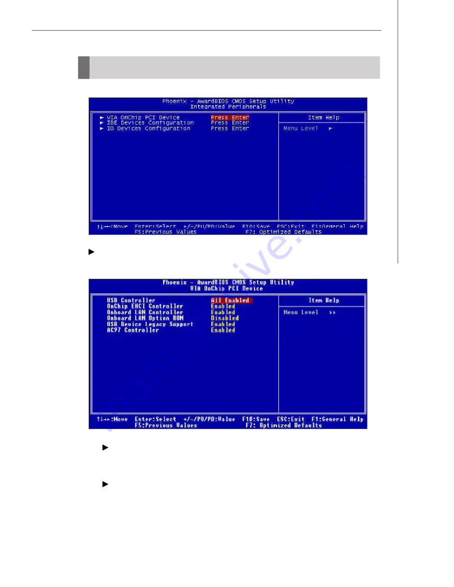
Integrated Peripherals

 VIA OnChip PCI Device

Press <Enter> and the following sub-menu appears:

 USB  Controller

Select  [Enabled] if  your  system  contains  a  Universal  Serial  Bus  (USB)
controller and  you have USB peripherals.

 OnChip EHCI Controller

This setting disables/enables the OnChip EHCI controller. The Enhanced
Host Controller Interface (EHCI) specification describes the register-level
interface for a Host Controller for the Universal Serial Bus (USB) Revision
2.0.

Summary of Contents for Axis 700

Page 1: ...Axis 700 Axis 700 Lite MS 6427 V1 X Barebone G52 64271X1 ...

Page 2: ...to radio communications However there is no guarantee that interference will not occur in a particular installation If this equipment does cause harmful interference to radio or television reception which can be determined by turning the equipment off and on the user is encouraged to try to correct the interference by one or more of the measures listed below Reorient or relocate the receiving ante...

Page 3: ...t incorporates copyright protection technology that is protected by U S patents and other intellectual property rights Use of this copyright protection technol ogy must be authorized by Macrovision and is intended for home and other limited viewing uses only unless otherwise authorized by Macrovision Reverse engineering or disassembly is prohibited Revision History Revision Revision History Date v...

Page 4: ...ngs on the equipment should be noted 10 Never pour any liquid into the opening that could damage or cause electrical shock 11 If any of the following situations arises get the equipment checked by service personnel The power cord or plug is damaged Liquid has penetrated into the equipment The equipment has been exposed to moisture The equipment does not work well or you can not get it work accordi...

Page 5: ...G 0 75mm2 2 Internal part is hazardous moving parts please keep fingers and other body parts away 3 For pluggable equipment the socket outlet shall be installed near the equipment and shall be easily accessible 4 Do not disable the protective earth pin from the plug the equipment must be connected to an earthed mains socket outlet ...

Page 6: ...vi WEEE Statement ...

Page 7: ...vii ...

Page 8: ...viii ...

Page 9: ...8 Serial ATA Connectors SATA1 SATA2 2 9 Fan Power Connector SYSFAN1 2 10 CD In Connector CD_IN 2 10 Front Panel Audio Connector JAUD 2 10 Front Panel Connectors JFP1 JFP2 2 11 Chassis Intrusion Switch Connector JCI1 2 12 Front USB Connectors J3 J4 J5 2 12 Wake On LAN Connector J9 2 13 Jumper 2 14 Clear CMOS Jumper JBAT1 2 14 Slot 2 15 PCI Slot 2 15 Chapter 3 BIOS Setup 3 1 Entering Setup 3 2 Contr...

Page 10: ... Hard Disk Drive 4 7 Installing Hard Disk Drive 4 8 Installing Riser Card 4 8 Installing Card Reader 4 9 Installing Optical Disk Drive 4 9 Installing Memory Modules 4 10 Restoring Chassis Cover 4 12 Installing Footstand 4 13 Appendix A VIA VT1618 Audio A 1 Installing the Audio Driver A 2 Installation for Windows 98SE ME 2000 XP A 2 Software Configuration A 4 Speaker A 4 Mixer A 5 Speaker Test A 6 ...

Page 11: ...for purchasing Axis 700 MS 6427 barebone Axis 700 barebone is your best Slim PC choice With the fantastic appearance and ultra small form factor it can easily be set anywhere The fea ture packed platform also gives you an exciting PC experience ...

Page 12: ...uth Bridge VIA VT8237R chipset Memory Support Supports DDRII 400 533 SDRAM 2GB Max 1 DDRII DIMM 240pin 1 8V LAN Supports PCI LAN 10 100 Fast Ethernet by VIA VT6103L Audio Chip integrated by VIA VT1618 Flexible 5 1 channel audio with jack sensing Compliant with AC97 2 3 spec IDE One IDE port by VT8237R Supports Ultra DMA 66 100 133 mode Supports PIO Bus Master operation mode SATA Supports two SATA ...

Page 13: ...and COMB 2 USB 2 0 ports 1 LAN jack 3 flexible audio jacks 1 S Video port for standard only 1 DVI port for standard only 1 VGA oort On Board Pinheaders 3 USB 2 0 pinheaders 1 audio pinheader Slots 1 PCI slot Supports 3 3V 5V PCI bus Interface Form Factor Mini ITX 17 cm X 17 cm Mounting 4 mounting holes ...

Page 14: ... 1 4 1 Mic In pink 6 Optical Drive Eject Close Button 2 Headphone Out green 7 Card Reader Drive optional 3 USB 2 0 ports x 2 8 Power LED 4 Power Button 9 Optical Drive optional 5 HDD LED System Configuration Front View ...

Page 15: ...yboard purple 8 Mic In pink 2 PS 2 Mouse green 9 Line Out green 3 DVI Port for standard only 10 Line In blue 4 VGA Port D Sub15 11 Power Jack 5 S Video for standard only 12 Ventilation Hole 6 USB 2 0 Ports 13 LAN Jacks RJ45 7 Serial Ports 14 Expansion Slots ...

Page 16: ... View Lite Version 1 PS 2 Keyboard purple 7 Line Out green 2 PS 2 Mouse green 8 Line In blue 3 VGA Port D Sub15 9 Power Jack 4 USB 2 0 Ports 10 Ventilation Hole 5 Serial Ports 11 LAN Jacks RJ45 6 Mic In pink 12 Expansion Slots ...

Page 17: ...mension 363mm D x 300mm W x 72mm H Minimized screw structure Detachable bay housing Multiple ventilation holes 1 System Ventilation Hole 3 CPU Fan Ventilation Hole 2 Power Supply Ventilation Hole 4 System Ventilation Hole Bottom Side Back ...

Page 18: ...MS 6427 Barebone 1 8 System Picture Front Panel Ventilation Hole System Fan Power Supply Ventilation Hole Ventilation Hole Power Supply Fan sharp ...

Page 19: ... completed please keep other objects away from the ventilation hole at least 2 5cm and above Do not block the ventila tion hole System Air Flow Direction Front Panel Ventilation Hole Power Supply Fan Power Supply Ventilation Hole Ventilation Hole ...

Page 20: ...the installation procedures For some components if you install in the wrong orientation the components will not work properly Use a grounded wrist strap before handling com puter components Static electricity may damage the components Chapter 2 Hardware Setup Always unplug the power cord before in serting any add on card or module ONLY FOR SERVICE PERSONEL ...

Page 21: ...VIA VT1622A JCI1 J9 SATA1 SATA2 DIMM1 IDE1 JFP2 ATXPWR SYSFAN1 JFP1 J4 J3 J5 JBAT1 BATT BIOS VIA VT8237R Plus VIA C7 VIA CN700 Top mouse Bottom KB Top VGA Port Bottom DIV Port for standard only Top COMA Bottom COMB Top LAN Jack Bottom USB ports S Video Out for standard only T MIC In M Line In B SS Out JAUD CD_IN ...

Page 22: ...n the socket 3 The plastic clip at each side of the DIMM slot will automatically close The mainboard provides one slot for 240 pins non ECC DDRII DIMM which supports the memory size up to 2GB For more information on compatible components please visit http www msi com tw program products slim_pc slm pro_slm_cpu_support php Memory Volt Notch DDRII 240 pins 1 8V 56 x 2 112 pins 64 x 2 128 pins Import...

Page 23: ...e plug of the power supply is inserted in the proper orientation and the pins are aligned Then push down the power supply firmly into the connector Power Supply ATXPWR 20 10 11 1 Important 1 Make sure that the connector is connected to proper ATX power supplies to ensure stable operation of the mainboard 2 Power supply of 130 watts and above is highly recommended for system stability SIGNAL 3 3V 3...

Page 24: ...l Host Controller Interface Universal Serial Bus root for attaching USB devices such as keyboard mouse or other USB compatible devices You can plug the USB devices directly into these connectors Front Panel The Front Panel provides the following connectors USB Ports USB Ports Headphone Out green Mic In pink Headphone Out green Mic In pink ...

Page 25: ...ur monitor refer to your monitor manual for more information S Video Connector for standard only The S Video connector allows users to connect display devices for component video input output S Video Super Video sometimes referred to as Y C Video or component video is a video signal transmission in which the luminance signal and the chrominance signal are transmitted separately to achieve superior...

Page 26: ...dio devices You can differentiate the color of the audio jacks for different audio sound effects Blue audio jack Line In in 5 1 channel mode is used for external CD player tapeplayer or other audio devices Green audio jack Line Out is a connector for speakers or headphones Pink audio jack Mic In is a connector for microphones LAN RJ 45 Jack The standard RJ 45 jack is for connection to single Local...

Page 27: ... interface is one third faster than earlier record breaking Ultra ATA 100 technol ogy and is backwards compatible with the existing Ultra ATA interface IDE Primary IDE Connector The first hard drive should always be connected to IDE1 IDE1 can connect a Master and a Slave drive You must configure second hard drive to Slave mode by setting the jumper accordingly Connectors IDE1 Important If you inst...

Page 28: ...al ATA 1 0 specifications Each Serial ATA connector can connect to 1 hard disk device SATA1 SATA2 7 7 1 1 Connect to SATA1 2 Serial ATA cable 1 3 5 7 Pin Definition PIN SIGNAL PIN SIGNAL 2 4 6 GND RXP TXN GND RXN GND TXP Take off the Dust Cover and connect to the Hard Disk Devices Important Please do not fold the Serial ATA cable into 90 degree angle Otherwise data loss may occur during transmissi...

Page 29: ...CD_IN This connector is provided for CD ROM audio CD_IN R L GND Front Panel Audio Connector JAUD The JAUD front panel audio connector allows you to connect to the front panel audio and is compliant with Intel Front Panel I O Con nectivity Design Guide Pin Definition PIN 1 2 3 4 5 6 7 8 9 10 SIGNAL AUD_MIC AUD_GND AUD_MIC_BIAS AUD_VCC AUD_FPOUT_R AUD_RET_R HP_ON KEY AUD_FPOUT_L AUD_RET_L DESCRIPTIO...

Page 30: ...Out connector on the back panel will not function 10 9 6 5 2 1 10 9 Reset Switch Power Switch HEE LED Power LED PIN 1 3 5 7 SIGNAL GND SLED PLED N C Pin Definition PIN 2 4 6 8 SIGNAL SPK BUZ BUZ SPK PIN 1 2 3 4 5 6 7 8 9 SIGNAL HD_LED_P FPPWR SLP HD_LED_N FPPWR SLP RST_SW_N PWR_SW_P RST_SW_P PWR_SW_N RSVD_DNU DESCRIPTION Hard disk LED pull up MSG LED pull up Hard disk active LED MSG LED pull up Re...

Page 31: ...he record JCI1 CINTRU 1 2 GND Front USB Connectors J3 J4 J5 The mainboard provides three standard USB 2 0 pinheaders USB 2 0 technology increases data transfer rate up to a maximum throughput of 480Mbps which is 40 times faster than USB 1 1 and is ideal for connecting high speed USB interface peripherals such as USB HDD digital cameras MP3 players printers modems and the like VCC USB0 USB0 GND Key...

Page 32: ...or rectly to avoid possible damage Connect to J3 J4 J5 USB 2 0 Bracket Optional Wake On LAN Connector J9 This connector allows you to connect to a LAN card with Wake On LAN function You can wake up the computer via remote control through a local area network J9 MP_WAKEUP 1 3 GND 5VSB ...

Page 33: ...attery to keep the system configuration data With the CMOS RAM the system can automatically boot OS every time it is turned on If you want to clear the system configuration use the JBAT1 Clear CMOS Jumper to clear data Fol low the instructions below to clear the data Jumper JBAT1 Keep Data Clear Data 1 3 1 3 1 3 Important You can clear CMOS by shorting 2 3 pin while the system is off Then return t...

Page 34: ...eral Component Interconnect Slot The PCI slot supports LAN cards SCSI cards USB cards and other add on cards that comply with PCI specifications At 32 bits and 33 MHz it yields a throughput rate of 133 MBps Slot PCI Slot Riser Card ...

Page 35: ...e BIOS Setup program and allows you to configure the system for optimum use You may need to run the Setup program when An error message appears on the screen during the system booting up and requests you to run SETUP You want to change the default settings for custom ized features ...

Page 36: ...e items under each BIOS category described in this chapter are under continuous update for better system performance Therefore the description may be slightly dif ferent from the latest BIOS and should be held for reference only 2 Upon boot up the 1st line appearing after the memory count is the BIOS version It is usually in the format W7265IMS V1 0 060715 where 1st digit refers to BIOS maker as A...

Page 37: ...sub menu Then you can use the control keys to enter values and move from field to field within a sub menu If you want to return to the main menu just press the Esc General Help F1 The BIOS setup program provides a General Help screen You can call up this screen from any menu by simply pressing F1 The Help screen lists the appropriate keys to use and the possible selections for the highlighted item...

Page 38: ...chipset registers and optimize your system s performance Integrated Peripherals Use this menu to specify your settings for integrated peripherals Power Management Setup Use this menu to specify your settings for power management PnP PCI Configurations This entry appears if your system supports PnP PCI H W Monitor This entry shows your PC health status Cell Menu Use this menu to specify your settin...

Page 39: ...ult values set by the mainboard manufacturer specifically for optimal performance of the mainboard BIOS Setting Password Use this menu to set the password for BIOS Save Exit Setup Save changes to CMOS and exit setup Exit Without Saving Abandon all changes and exit setup ...

Page 40: ...ay Day of the week from Sun to Sat determined by BIOS Read only Month The month from Jan through Dec Date The date from 1 to 31 can be keyed by numeric function keys Year The year can be adjusted by users Time hh mm ss This allows you to set the system time that you want usually the current time The time format is hour minute second Standard CMOS Features ...

Page 41: ...drive will show up on the right hand according to your selection Press Enter for the sub menu of each item LBA Large Mode This item allows you to enable or disable the LBA Logical Block Address the logical block size in hard disk mode DMA Mode This item allows you to enable or disable the DMA Direct Memory Access mode ...

Page 42: ... change any values in the Total Memory fields read only BIOS Version This item shows the BIOS version of your system read only CPU ID uCode IO Frequency The three items show the CPU related information of your system read only System Information Press Enter and the following sub menu appears ...

Page 43: ...ince it will skip some check items CPU Feature Press Enter for the sub menu of each item Thermal Management This setting specifies the thermal technologies implemented in the Pentium M processor TM2 Bus Ratio TM2 Bus VID These settings specify the multiplier and VID values used by the pro cessor in TM2 Thermal Monitor 2 mode ...

Page 44: ...boot IOAPIC Function This field is used to enable or disable the APIC Advanced Programmable Interrupt Controller Due to compliance with PC2001 design guide the system is able to run in APIC mode Enabling APIC mode will expand available IRQ resources for the system MPS Table Version This field allows you to select which MPS Multi Processor Specification ver sion to be used for the operating system ...

Page 45: ...select the first boot hard disk 1st Boot Device 2nd Boot Device 3rd Boot Device These items allow you to set the sequence of boot devices where BIOS attempts to load the disk operating system Boot Other Device Setting the option to Enabled allows the system to try to boot from other device if the system fails to boot from the 1st 2nd 3rd boot device ...

Page 46: ...trol Press Enter and the following sub menu appears DRAM Clock Use this field to configure the clock frequency of the installed DRAM Be careful with the three hooks on the Front Panel Remember to remove them gently with hands or the damages can be made easily Important ...

Page 47: ...d of write data burst and the start of a column read command It allows I O gating to overdrive sense amplifiers before read command starts Write Recovery Time Twr Minimum time interval between end of write data burst and the start of a precharge command Allows sense amplifiers to restore data to cells DRAM Command Rate This setting controls the DRAM command rate Select 1T Command allows DRAM singl...

Page 48: ... has an embedded 32 bit posted write buffer to support delay transactions cycles Select Enabled to support compliance with PCI specification version 2 1 VLink mode selection This item lets you choose the speed mode between the North Bridge South Bridge VLink 8X Support This item enables or disables the 8X VLink Data Rate DRDY_Timing This item allows you to select the DRDY Timing from Slowest Defau...

Page 49: ...d if your system contains a Universal Serial Bus USB controller and you have USB peripherals OnChip EHCI Controller This setting disables enables the OnChip EHCI controller The Enhanced Host Controller Interface EHCI specification describes the register level interface for a Host Controller for the Universal Serial Bus USB Revision 2 0 ...

Page 50: ...abled if you need to use any USB 1 1 2 0 device in the operating system that does not support or have any USB 1 1 2 0 driver installed such as DOS and SCO Unix Set to Disabled only if you want to use any USB device other than the USB mouse AC97 Controller Auto allows the mainboard to detect whether an audio device is used If an audio device is detected the onboard AC97 Audio Codec 97 controller wi...

Page 51: ...ATA controller SATA Mode This setting is used to select the SATA mode The setting are IDE Set SATA HDD as IDE mode RAID RAID enabled PCI IDE BusMaster Set this option to Enabled to specify that the IDE controller on the PCI local bus has bus mastering capability OnChip IDE Channel0 The integrated peripheral controller contains an IDE interface with support for two IDE channels Choose Enabled to ac...

Page 52: ... interface set this option to Disabled if the interface does not support prefetching Onboard Serial Port 1 2 These items specify the base I O port address and IRQ for the onboard Serial Port A COM A Serial Port B COM B Selecting Auto allows BIOS to automatically determine the correct base I O port address IO Devices Configuration Press Enter and the following sub menu appears ...

Page 53: ...g of this field Setting options S1 POS The S1 sleep mode is a low power state In this state no system context is lost CPU or chipset and hardware main tains all system context S3 STR The S3 sleep mode is a lower power state where the infor mation of system configuration and open applications files is saved to main memory that remains powered while most other hardware components turn off to save en...

Page 54: ...to configure the Power Button function Settings are Power Off The power button functions as a normal power on off button Suspend When you press the power button the computer enters the suspend sleep mode but if the button is pressed for more than four seconds the computer is turned off Restore On AC Power Loss This setting specifies whether your system will reboot after a power failure or interrup...

Page 55: ...ctivity Resume From S3 By USB Device The item allows the activity of the USB device to wake up the system from S3 Suspend to RAM sleep state Resume From S3 By PS 2 KB The item specifies how the system will be awakened from power saving mode when input signal of the PS 2 keyboard is detected Use the PageUp PageDown keys to select the options When select ing Password enter the desired password Resum...

Page 56: ...ed this setting allows your system to be awakened from the power saving modes through any event on PME Power Management Event Resume By RTC Alarm This is used to enable or disable the feature of booting up the system on a scheduled time date from the S3 S4 and S5 state ...

Page 57: ...I device can hold the bus before another takes over When set to higher values every PCI device can conduct transac tions for a longer time and thus improve the effective PCI bandwidth For better PCI performance you should set the item to higher values IRQ Resources The items are adjustable only when Resources Controlled By is set to Manual Press Enter and you will enter the sub menu of the items I...

Page 58: ... Barebone 3 24 IRQ 3 15 assigned to These fields specify whether the system will be awakened from power saving modes when activity or input signal of the specified hardware peripheral or component is detected ...

Page 59: ...he CPU overheating problem This item is available only when your OS supports this function such as Windows ME XP Chassis Intrusion The field enables or disables the feature of recording the chassis intrusion status and issuing a warning message if the chassis is once opened To clear the warning message set the field to Reset The setting of the field will automatically return to Enabled later ...

Page 60: ...lth status Press Enter and the following sub menu appears System CPU Temperature System Fan Speed CPU Vcore 12V 5V 5VSB 3 3V These items display the current status of all of the monitored hardware devices components such as CPU voltages temperatures and all fans speeds ...

Page 61: ...Interference The Spread Spec trum function reduces the EMI generated by modulating the pulses so that the spikes of the pulses are reduced to flatter curves Important 1 If you do not have any EMI problem leave the setting at Disabled for optimal system stability and performance But if you are plagued by EMI select the value of Spread Spectrum for EMI reduction 2 The greater the Spread Spectrum val...

Page 62: ...zed Defaults are the default values set by the mainboard manufacturer specifically for optimal performance of the mainboard When you select Load Optimized Defaults a message as below appears Pressing Y loads the default factory settings for optimal system performance ...

Page 63: ...nd press Enter You may also press Esc to abort the selection and not enter a password To clear a set password just press Enter when you are prompted to enter the password A message will show up confirming the password will be disabled Once the password is disabled the system will boot and you can enter Setup without entering any password When a password has been set you will be prompted to enter i...

Page 64: ...cedures While doing the installation be careful in holding the components and follow the installation procedures Use a grounded wrist strap before handling computer components Static electricity may damage the components Always unplug the power cord before in serting any add on card or module ONLY FOR SERVICE PERSONEL ...

Page 65: ...to install Memory Modules Riser Card Card Reader Hard Disk Drive and Optical Disk Drive Installation Tools Screws Two types of screws are used in assembling the barebone Screw type 1 M3XL4 Screw type 2 6 32 Screwdriver Gloves Overview Screw type 1 M3XL4 This screw is used to lock the Top Cover Card Reader Riser Bracket FDD and ODD Screw type 2 6 32 This screw is used to lock the Power Supply and H...

Page 66: ...ystem please check the items listed below for basic system operation The Footstand and the CPU cooler are included in the package other items are optional Footstand IDE or SATA HDD Optional Card Reader Optional Optical Drive Optional DDRII SDRAM Optional Riser Card ...

Page 67: ...move the Top Cover from the system with hands 1 Removing Top Cover Installation Procedures Remove the Front Panel from the system with hands to release all the cages Important Be careful with the three hooks on the Front Panel Remember to remove them gently with hands or the damages can be made easily ...

Page 68: ...4 5 System Assembly 2 Removing Optical Disk Drive ODD Disconnect the cable and the power cord of the ODD Optional Pull the Lock Bracket to release the ODD Remove the ODD from the system This direction ...

Page 69: ...lock the four screws to release the Card Reader Press Press Important 3 Removing Card Reader Disconnect the cable of Card Reader Optional This multi function Card Reader tray is designed to be a 3 in 1 device with three different choices for installtion which includes the Card Reader itself HDD and FDD ...

Page 70: ...e the HDD tray from the sys tem with hands Unlock the screw from the chassis with screwdriver Remove the Riser Card Support Bracket from the system with hands Lift up Lift up 4 Removing Riser Card 5 Removing Hard Disk Drvie HDD ...

Page 71: ...ands Lock the screw to the chassis with screwdriver Install the Riser Card Support Bracket to the system with hands Put down 6 Installing Hard Disk Drvie HDD 7 Installing Riser Card Insert the HDD Optional into theHDD tray and lock the four screws Put down Insert ...

Page 72: ...cket Remember to lock the four screws to fix the Card Reader before inserting Insert the ODD into the system Important Press Press Connect the cable of Card Reader Optional 8 Installing Card Reader 9 Installing Optical Disk Drive ODD Please note that the length of the ODD should be under 185MM ...

Page 73: ...MS 6427 Barebone 4 10 Find the location of DIMM slot 10 Installing Memory Modules Push the Lock Bracket to fix the ODD Connect the cable and the power cord of the ODD Optional This direction ...

Page 74: ...4 11 System Assembly Insert the Memory Modules vertically into the DIMM slot Put down ...

Page 75: ...bone 4 12 13 Restoring Top Cover Important Follow the steps to restore the Top Cover to the system with hands Lock the two screws on the Back Panel with screwdriver Restore the Front Panel to the sys tem with hands ...

Page 76: ...Assembly Horizontal Type Tower Type 5 Installing Footstand Move the system until its bottom part fit against the end of the footstand Place the footstand on the table Lift up the system and put it on the footstand ...

Page 77: ...rd is equipped with VIA VT1618 chip which provides support for 6 channel audio output VIA VT1618 allows the board to attach 4 or 6 speak ers for better surround sound effect The section will tell you how to install and use 4 6 channel audio func tion on the board ...

Page 78: ...d could look slightly different if you install the drivers in different operating systems Special Notice during Installation Once you are finishing the installation of your system please right click on My Computer on the desktop and choose Properties Hardware Device Manager If you can see the question mark next to the Other devices Multimedia Audio Controller it means the system detects the audio ...

Page 79: ... will find the icon in the system tray and on the desktop Double click the icon on the desktop or right click on the icon in the system tray Also you can right click on the icon in the system tray and choose VIA Audio Deck and the following screen will appear to show some basic settings about the audio configuration ...

Page 80: ...ect the channels you would like to use here For the expander and Center Subwoofer speaker exchange please check the Exchange Center LFT check boxes You have to check the Enable Stereo Sound Expander check box in Effect tab and the Enable Smart51 Plus blue jack for side surround and red jack for center LEF speakers output check box in PhoneJack tab if you intend to use 4 or 5 1 channel sound effect...

Page 81: ...lick the allow button to the right for more outputs n Recording Here you can choose the preferred recording input Choosing Mic allows you to record the audio through the connected microphones Line In allows you to record to record through the connected line in device and etc Choosing Stereo Mixer allows you to record the audio through all inputs ...

Page 82: ...Speaker Test Here you can click on each speaker to test its function and increase decrease the volume Information Here it provides the information about Vinyl Deck including the driver version codec type and OS version etc ...

Page 83: ... utility connect your speakers to the correct phone jacks in accordance with the setting in software utility n 2 Channel Mode for Stereo Speaker Output Refer to the following diagram and caption for the function of each phone jack on the back panel when 2 Channel Mode is selected 1 Line In 2 Line Out Front channels 3 MIC In Back Panel 2 3 1 ...

Page 84: ...r 4 Speaker Output Description Connect two speakers to back panel s Line Out connector and two speakers to the real chan nel Line Out connector Back Panel 2 3 1 4 Channel Analog Audio Output 1 Side Surround 2 Line Out Front channels 3 MIC In ...

Page 85: ... Connect two speakers to back panel s Line Out connector two speakers to the rear channel Line Out connector and two speakers to the center LFE chan nel Line Out connector Back Panel 2 3 1 6 Channel Analog Audio Output 1 Side Surround 2 Line Out Front channels 3 Center LFE ...

Reviews: