background image

1

Unpacking

Unpacking

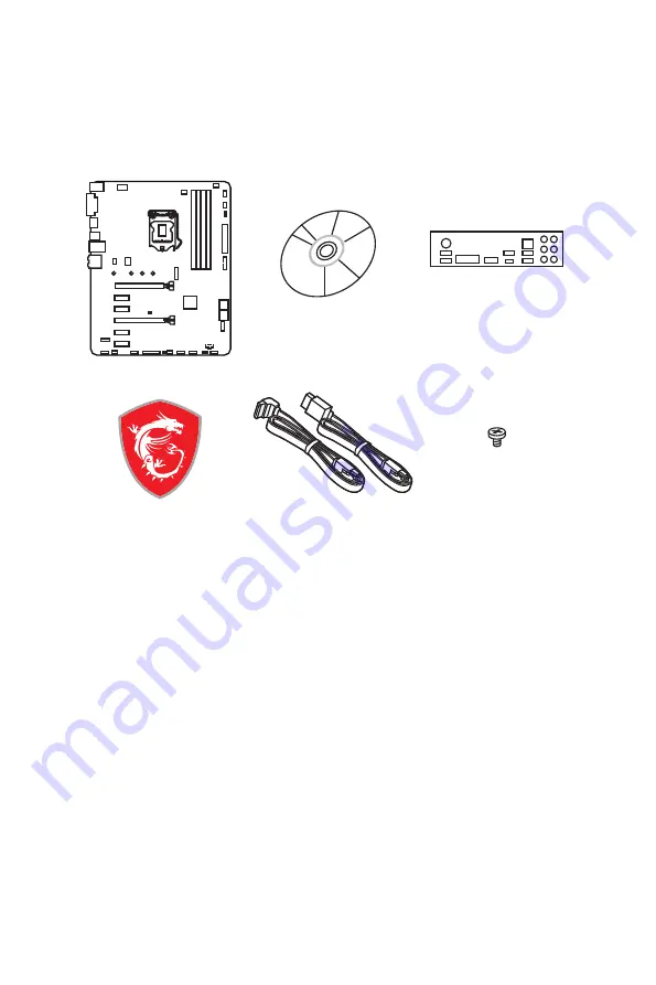
Thank you for buying the MSI

®


B360-A PRO


motherboard. Check to make sure your 

motherboard box contains the following items. If something is missing, contact your 

dealer as soon as possible.

SATA Cable x2

Drivers & Utilities 

Disc

I/O Shield

Motherboard

Case Badge

M.2 Screw x1

Summary of Contents for B360-A PRO

Page 1: ...e MSI B360 A PRO motherboard Check to make sure your motherboard box contains the following items If something is missing contact your dealer as soon as possible SATA Cable x2 Drivers Utilities Disc I...

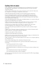
Page 2: ...computer before installation is completed This could cause permanent damage to the components as well as injury to the user y If you need help during any installation step please consult a certified c...

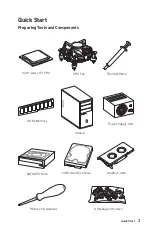
Page 3: ...Intel LGA 1151 CPU DDR4 Memory Graphics Card SATA Hard Disk Drive SATA DVD Drive A Package of Screws Phillips Screwdriver Chassis Power Supply Unit CPU Fan Thermal Paste Quick Start Preparing Tools a...

Page 4: ...4 Quick Start http youtu be bf5La099urI Installing a Processor 1 2 3 6 4 5 7 8 9...

Page 5: ...5 Quick Start 1 1 2 2 3 3 Installing DDR4 memory http youtu be T03aDrJPyQs DIMMB2 DIMMB2 DIMMB1 DIMMA2 DIMMA2 DIMMA2 DIMMA1...

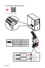
Page 6: ...9 JFP1 1 HDD LED 2 Power LED 3 HDD LED 4 Power LED 5 Reset Switch 6 Power Switch 7 Reset Switch 8 Power Switch 9 Reserved 10 No Pin R E S E T S W P O W E R S W P O W E R L E D P O W E R L E D H D D L...

Page 7: ...7 Quick Start BAT1 Installing the Motherboard 1 2...

Page 8: ...8 Quick Start Installing SATA Drives http youtu be RZsMpqxythc 1 2 3 4 5...

Page 9: ...9 Quick Start 1 Installing a Graphics Card http youtu be mG0GZpr9w_A 2 3 4 5 6...

Page 10: ...10 Quick Start Connecting Peripheral Devices...

Page 11: ...11 Quick Start Connecting the Power Connectors http youtu be gkDYyR_83I4 ATX_PWR1 CPU_PWR1 PCIE_PWR1...

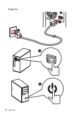
Page 12: ...12 Quick Start Power On 1 4 2 3...

Page 13: ...dio Ports Configuration 20 Realtek HD Audio Manager 21 Overview of Components 23 CPU Socket 25 DIMM Slots 26 PCI_E1 6 PCIe Expansion Slots 27 M2_1 M 2 Slot Key M 28 SATA1 5 SATA 6Gb s Connectors 29 CP...

Page 14: ...HARDWARE MONITOR 61 Software Description 63 Installing Windows 10 63 Installing Drivers 63 Installing Utilities 63 APP MANAGER 64 LIVE UPDATE 6 65 COMMAND CENTER 67 X BOOST 71 SMART TOOL 73 RAMDISK 7...

Page 15: ...0 60Hz Multi GPU y Supports 2 Way AMD CrossFire Technology Storage Intel B360 Chipset y 5x SATA 6Gb s ports y 1x M 2 slot Key M Supports up to PCIe 3 0 x4 and SATA 6Gb s 2242 2260 2280 22110 storage d...

Page 16: ...connector y 1x 8 pin ATX 12V power connector y 1x 6 pin ATX PCIe power connector y 5x SATA 6Gb s connectors y 1x USB 3 1 Gen1 connector supports additional 2 USB 3 1 Gen1 ports y 2x USB 2 0 connector...

Page 17: ...x 24 3 cm BIOS Features y 1x 128 Mb flash y UEFI AMI BIOS y ACPI 6 1 SM BIOS 2 8 y Multi language Software y Drivers y APP MANAGER y SUPER CHARGER y COMMAND CENTER y LIVE UPDATE 6 y SMART TOOL y RAMD...

Page 18: ...tel LAN with Network Manager y Storage Turbo M 2 y Fan Pump Fan Smart Fan Control y LED EZ DEBUG LED y Protection PCI E Steel Armor y Performance Multi GPU CrossFire Technology DDR4 Boost USB with Typ...

Page 19: ...1 x M 2 6 x USB 2 0 PCI Express Bus P S2 Mouse Keyboard Audio Jacks DMI 3 0 chipset CPU NV6797 Super I O Realtek ALC892 PCI Express Bus DisplayPort DVI D PCIe x1 slot PCIe x1 slot 5 x SATA 6Gb s x1 x...

Page 20: ...ps connection Green 100 Mbps connection Orange 1 Gbps connection LAN Port LED Status Table Audio Ports Configuration PS 2 LAN USB 2 0 Audio Ports DVI D DisplayPort USB 3 1 Gen2 USB 3 1 Gen1 USB 3 1 Ge...

Page 21: ...volume or balance the right left side of the speakers that you plugged in front or rear panel by adjust the bar y Profiles toggles between profiles y Advanced Settings provides the mechanism to deal...

Page 22: ...Rear I O Panel Audio jacks to headphone and microphone diagram Audio jacks to stereo speakers diagram Audio jacks to 7 1 channel speakers diagram AUDIO INPUT Rear Front Side Center Subwoofer AUDIO INP...

Page 23: ...I_E2 PCI_E3 PCI_E4 PCI_E5 PCI_E6 CPU Socket CPU_PWR1 PCIE_PWR1 ATX_PWR1 JUSB4 JUSB2 SYS_FAN3 JBAT1 SATA 2 3 SATA 4 5 SATA1 M2_1 DIMMA1 DIMMA2 DIMMB1 DIMMB2 SYS_FAN1 SYS_FAN4 EZ Debug LEDs JTBT1 JTPM1...

Page 24: ...JAUD1 Front Audio Connector 34 JBAT1 Clear CMOS Reset BIOS Jumper 37 JCI1 Chassis Intrusion Connector 34 JCOM1 Serial Port Connector 36 JFP1 JFP2 Front Panel Connectors 31 JLPT1 Parallel Port Connecto...

Page 25: ...before booting your system y Overheating can seriously damage the CPU and motherboard Always make sure the cooling fans work properly to protect the CPU from overheating Be sure to apply an even layer...

Page 26: ...GB or less for 32 bit Windows OS due to the memory address limitation Therefore we recommended that you to install 64 bit Windows OS if you want to install more than 4GB memory on the motherboard y So...

Page 27: ...ation with optimum performance using the PCI_E1 slot is recommended y When adding or removing expansion cards always turn off the power supply and unplug the power supply power cable from the power ou...

Page 28: ...video to learn how to Install M 2 module http youtu be JCTFABytrYA 1 2 3 30 Installing M 2 SSD 1 Loosen the M 2 riser screw from the motherboard 2 Move and fasten the M 2 riser screw to the appropria...

Page 29: ...old the SATA cable at a 90 degree angle Data loss may result during transmission otherwise y SATA cables have identical plugs on either sides of the cable However it is recommended that the flat conne...

Page 30: ...23 5V 12 3 3V 24 Ground 5 4 1 8 CPU_PWR1 1 Ground 5 12V 2 Ground 6 12V 3 Ground 7 12V 4 Ground 8 12V Important Make sure that all the power cables are securely connected to a proper ATX power supply t...

Page 31: ...Speaker 2 Buzzer 3 Buzzer 4 Speaker JUSB4 USB 3 1 Gen1 Connector This connector allows you to connect USB 3 1 Gen1 ports on the front panel 1 10 11 20 1 Power 11 USB2 0 2 USB3_RX_DN 12 USB2 0 3 USB3_...

Page 32: ...rn ON OFF the Charging mode Video Demonstration Watch the video to learn how to charge the smartphone with Super Charger http youtu be FCyvjr5NbOw Important When the Charging mode is enabled the Charg...

Page 33: ...on below to adjust the fan connector to PWM or DC Mode Switching fan mode and adjusting fan speed You can switch between PWM mode and DC mode and adjust fan speed in BIOS HARDWARE MONITOR Select PWM m...

Page 34: ...intrusion detector 1 Connect the JCI1 connector to the chassis intrusion switch sensor on the chassis 2 Close the chassis cover 3 Go to BIOS SETTINGS Security Chassis Intrusion Configuration 4 Set Cha...

Page 35: ...2 10 No Pin 11 LPC address data pin3 12 Ground 13 LPC Frame 14 Ground JTPM1 TPM Module Connector This connector is for TPM Trusted Platform Module Please refer to the TPM security platform manual for...

Page 36: ...tional serial port with bracket 1 2 26 25 1 RSTB 2 AFD 3 PRND0 4 ERR 5 PRND1 6 PINIT 7 PRND2 8 LPT_SLIN 9 PRND3 10 Ground 11 PRND4 12 Ground 13 PRND5 14 Ground 15 PRND6 16 Ground 17 PRND7 18 Ground 19...

Page 37: ...ng device is not detected or fail JBAT1 Clear CMOS Reset BIOS Jumper There is CMOS memory onboard that is external powered from a battery located on the motherboard to save system configuration data I...

Page 38: ...wing methods to enter BIOS setup y Press Delete key when the Press DEL key to enter Setup Menu F11 to enter Boot Menu message appears on the screen during the boot process y Use MSI FAST BOOT applicat...

Page 39: ...e BIOS Setup during POST 2 Insert the USB flash drive that contains the update file into the computer 3 Select the M FLASH tab and click on Yes to reboot the system and enter the flash mode 4 Select a...

Page 40: ...ode switch press this tab or the F7 key to switch between Advanced mode and EZ mode y Screenshot click on this tab or the F12 key to take a screenshot and save it to USB flash drive FAT FAT32 format o...

Page 41: ...rol the fan speed by percentage y Favorites menu press the F3 key to enter Favorites menu It allows you to create personal BIOS menu where you can save and access favorite frequently used BIOS setting...

Page 42: ...Mode Overview section y BIOS menu selection the following options are available SETTINGS allows you to specify the parameters for chipset and boot devices OC allows you to adjust the frequency and vo...

Page 43: ...en time elements The time format is hour minute second f SATA PortX M2_X Shows the information of connected SATA M 2 devices Important If the connected SATA device is not displayed turn off computer a...

Page 44: ...ter to enter the sub menu fPower LED Blinking Sets shining behaviors of the onboard Power LED Dual Color The power LED turns to another color to indicate the S3 state Blinking The power LED blinks to...

Page 45: ...ction for NVMe or PCIe storage devices fM2_1 RST Pcie Storage Remapping Disabled Enables or disables M 2 PCIe storage remapping for Intel Rapid Storage fM 2 Optane Genie Disabled Enables or disables M...

Page 46: ...operating system without XHCI hand off feature fLegacy USB Support Enabled Sets Legacy USB function support Auto The system will automatically detect if any USB device is connected and enable the leg...

Page 47: ...abled Disables this function fRestore after AC Power Loss Power Off Sets the system behaviors while encountering the AC power loss Power Off Leaves the system in power off state after restoring AC pow...

Page 48: ...nabled fSecure Boot Sets the Windows secure boot to prevent the unauthorized accessing Press Enter to enter the sub menu This sub menu will appear when Windows 10 WHQL Support is enabled fSecure Boot...

Page 49: ...e is detected Disabled Disables this function fResume by USB Device Disabled Enables or disables the system wake up by USB devices Enabled Enables the system to be awakened from sleep state when activ...

Page 50: ...k state upon bootup f Info Block effect Unlock Sets the state of Help information block Unlock Sliding effect Lock Fix the Help information block on the screen f Boot Mode Select LEGACY UEFI Sets the...

Page 51: ...yped now will replace any previous set password from CMOS memory You will be prompted to confirm the password You may also press Esc to abort the selection To clear a set password press Enter when you...

Page 52: ...ve all changes and reboot the system f Save Changes Save current changes f Discard Changes Discard all changes and restore to the previous values f Restore Defaults Restore or load all default values...

Page 53: ...This item only appears when a CPU that supports Turbo Boost is installed All Core Enables the CPU Ratio All CPU cores will run the same CPU ratio that be set in CPU Ratio Per Core Enables the Core X...

Page 54: ...core frequency dynamically It can decrease average power consumption and average heat production Disabled Disables EIST fIntel Turbo Boost Enabled Enables or disables the Intel Turbo Boost This item...

Page 55: ...o the memory will not be initialed and trained when booting to accelerate the system booting time Disabled The memory will be initialed and trained every booting f CPU Voltages control Auto These opti...

Page 56: ...ows you to select the number of active CPU cores fLimit CPUID Maximum Disabled Enables or disables the extended CPUID value Enabled BIOS limits the maximum CPUID input value to circumvent boot problem...

Page 57: ...ower management technology defined by ACPI Auto This setting will be configured automatically by BIOS Enabled Detects the idle state of system and reduce CPU power consumption accordingly Disabled Dis...

Page 58: ...CPU package in Turbo Boost mode When the current is over the speci ed value the CPU will automatically reduce the core frequency for reducing the current fFCLK Frequency Auto Sets FCLK frequency Lowe...

Page 59: ...steps below to update BIOS 1 Insert the USB flash drive that contains the update file into the computer 2 Click on M FLASH tab a demand message will be prompted Click on Yes to reboot and enter the fl...

Page 60: ...rrent overclocking pro le fLoad Overclocking Profile 1 2 3 4 5 6 Load the current overclocking pro le fClear Overclocking Profile 1 2 3 4 5 6 Clear the current overclocking profile f OC Pro le Load fr...

Page 61: ...an control the fan speed automatically depending on the CPU temperature to keep it with in a specific range If the current CPU temperature reaches to the target value the Smart Fan function will be ac...

Page 62: ...62 BIOS Setup...

Page 63: ...r computer in Windows 10 2 Insert MSI Driver Disc into your optical drive 3 The installer will automatically appear and it will find and list all necessary drivers 4 Click Install button 5 The softwar...

Page 64: ...been installed successfully and it is available Double click on desired icon to access the application A refresh icon shows to inform you that the application has a update version Gray icon the icon w...

Page 65: ...ation tabs at the top You can click the tab to switch the control panel y Live Update When you launch LIVE UPDATE 6 you will see the Live update tab at first This tab allows you to select files to dow...

Page 66: ...he bottom 6 When Save Path prompt you can specify a download directory 7 When downloading you will see the screen below It may take several moments to complete the process 8 To install the application...

Page 67: ...trol Panel Previous Feature Next Feature Profile Buttons Option Buttons Page Indicator Resize Corner Profile Buttons y Default load the default values for the current feature y Apply apply your change...

Page 68: ...temperature The white dot will create strip chart in real time y System Fan Button to open the system fan control panel in new window y Fan Tune Button to automatically optimize the smart fan setting...

Page 69: ...tion Buttons Setting When click the Setting button The Record Warning and Mobile Control icons will appear y Record allows you to monitor the status of voltage fan speed and temperature in real time T...

Page 70: ...vate Wi Fi on your mobile device and connect to SoftAP with the SSID 6 Run MSI COMMAND CENTER APP on your mobile device 7 Find the IP address on the SoftAP Management Setting area and enter the IP add...

Page 71: ...meet your current system environment or support faster storage access speed for your external storage or memory cards Easy In Easy page you can select one system performance mode to meet the current s...

Page 72: ...y USB SPEED UP supports faster data transfer rates of the USB storage devices y STORAGE BOOST supports faster access speed of storage device y VR BOOST provides the optimized settings to boost the sys...

Page 73: ...he USB drive this process will erase it To create the Windows installation USB drive Step1 Choose source folder y In the Source folder box click Browse button and select the file from the dialog box T...

Page 74: ...ID in Windows system To create a super RAID 1 Use checkboxs to select the disks you want included in your RAID 2 Choose Speed Up or Backup for RAID type y Speed Up RAID0 y Backup RAID1 3 Click Start 4...

Page 75: ...etter Name Size and Format of the RAM disk y Option select browser temporary files to save load on the RAM disk You can also add software files to improve reading speed y Backup specify backup and res...

Page 76: ...es y Applications displays currently using network bandwidth applications You can prioritize Games Medias or File sharing programs as high as possible y Performance shows top 5 applications by total t...

Page 77: ...eed button which runs a speed test of your current total Internet bandwidth delivered through your Internet service provider To test the Upload and Download speed and con gure bandwidth please follow...

Page 78: ...y Module Installing the Intel Optane memory Install the Intel Rapid Storage Technology 16 or later 1 Update BIOS refer to the Updating BIOS section 2 Install the Intel Optane memory module Power off t...

Page 79: ...alog Reboot System WARNING Once you enable Intel Optane memory in order to prevent seriously damage your operating system please follow the cautions listed below y DO NOT set the SATA mode back to AHC...

Page 80: ...tel Optane memory 1 Disable Intel Optane Memory Disable Intel Optane Memory via the Intel Optane memory application Intel Rapid Storage Technology Click Yes in the dialog Reboot System 2 Disable M 2 O...

Page 81: ...e back to AHCI mode that may cause operating system damage MSI has developed a software assistance for this problem You can disable Intel Optane Memory and switch back to AHCI mode while keep the syst...

Page 82: ...then restart the computer y If 1 long 2 short beeps are heard remove and reinstall the graphics card and then restart the computer y Test with another known working graphics card The computer does not...

Page 83: ...not cause harmful interference and 2 this device must accept any interference received including interference that may cause undesired operation CE Conformity Products bearing the CE marking comply wi...

Page 84: ...equipos electr nicos no pueden ser depositados en los contenedores habituales de su municipio los fabricantes de equipos electr nicos est n obligados a hacerse cargo de dichos productos al termino de...

Page 85: ...tam nak v g n Az ilyen term keket a legk zelebbi gy jt helyre viheti ITALIANO Per proteggere l ambiente MSI da sempre amica della natura ti ricorda che In base alla Direttiva dell Unione Europea EU su...

Page 86: ...t prior notice Technical Support If a problem arises with your system and no solution can be obtained from the user guide please contact your place of purchase or local distributor Alternatively pleas...

Reviews: