background image

20

软件描述

软件��

�装

 Windows

®

 10

1. 

启动计算机电源�

2. 

 Windows

®

 10 

光盘放入您的光驱中�

3. 

按下计算机上的

 Restart 

按钮�

4. 

计算机

 POST (

开机自我测试

过程中按

 F11 

键进入启动菜单�

5. 

选择从菜单中启动光驱�

6. 

当屏幕显示

 Press any key to boot from CD or DVD... 

信息时按住任意键�

7. 

按照屏幕上的指示操作安装

 Windows

®

 10

�装驱动

1. 

启动您的计算机进入

 Windows

®

 10

2. 

 MSI

®


驱动光盘放入您光驱中�

3. 

安装界面将会自动出现,以及弹出一个对话框将列出所有必需的驱动程序�

4. 

点击

 Install 

按钮�

5. 

软件安装开始进行�完成安装后将提醒您重启�

6. 

点击

 OK 

按钮完成安装�

7. 

重新启动您的电脑�

�装工具

在�装工具�,��先完成驱动的�装�

1. 

 MSI

®


驱动光盘放入您光驱中�

2. 

安装界面将会自动出现�

3. 

点击

 Utilities 

选项卡�

4. 

选择您需要安装的工具�

5. 

点击

 Install 

按钮�

6. 

工具安装开始进行�完成安装后将提醒您重启�

7. 

点击

 OK 

按钮完成安装�

8. 

重新启动您的电脑�

Summary of Contents for B360M PRO-VDH

Page 1: ...tor 14 JCOM1 Serial Port Connector 14 JLPT1 Parallel Port Connector 14 CPU_FAN1 SYS_FAN1 2 Fan Connectors 15 JTPM1 TPM Module Connector 16 JTBT1 Thunderbolt Add on Card Connector 16 EZ Debug LED 16 JC...

Page 2: ...computer before installation is completed This could cause permanent damage to the components as well as injury to the user y If you need help during any installation step please consult a certified c...

Page 3: ...resolution of 1920x1200 60Hz y 1x HDMI port 1 4 supports a maximum resolution of 4096x2160 30Hz Storage Intel B360 Chipset y 6x SATA 6Gb s ports y 1x M 2 slot Key M Support up to PCIe 3 0 x4 and SATA...

Page 4: ...2V power connector y 6x SATA 6Gb s connectors y 1x USB 3 1 Gen1 connector supports additional 2 USB 3 1 Gen1 ports y 2x USB 2 0 connectors supports additional 4 USB 2 0 ports y 1x 4 pin CPU fan connec...

Page 5: ...UEFI AMI BIOS y ACPI 6 1 SM BIOS 2 8 y Multi language Software y Drivers y APP MANAGER y SUPER CHARGER y COMMAND CENTER y LIVE UPDATE 6 y SMART TOOL y RAMDISK y DPC LATENCY TUNER y FAST BOOT y X BOOS...

Page 6: ...Type C Line in Mic in Line out Audio 7 1 channel Configuration To configure 7 1 channel audio you have to connect front audio I O module to JAUD1 connector and follow the below steps 1 Click on the Re...

Page 7: ..._E3 ATX_PWR1 JUSB1 JUSB2 JUSB3 JBAT1 SATA 1 2 M2_1 JCI1 JFP1 SATA4 SATA5 SATA6 SATA3 JTBT1 JFP2 JAUD1 JLPT1 JCOM1 CPU Socket CPU_PWR1 DIMMA1 DIMMB1 DIMMB2 DIMMA2 SYS_FAN2 SYS_FAN1 CPU_FAN1 EZ Debug LE...

Page 8: ...e capacity of memory will be a little less than the amount of installed y Please note that the maximum capacity of addressable memory is 4GB or less for 32 bit Windows OS due to the memory address lim...

Page 9: ...nt overheating and maintain system stability y Confirm that the CPU heatsink has formed a tight seal with the CPU before booting your system y Overheating can seriously damage the CPU and motherboard...

Page 10: ...g Series Graphics Card Bolster to support its weight to prevent deformation of the slot y For a single PCIe x16 expansion card installation with optimum performance using the PCI_E1 slot is recommende...

Page 11: ...dentical plugs on either sides of the cable However it is recommended that the flat connector be connected to the motherboard for space saving purposes JFP1 JFP2 Front Panel Connectors These connector...

Page 12: ...5V 16 PS ON 5 Ground 17 Ground 6 5V 18 Ground 7 Ground 19 Ground 8 PWR OK 20 Res 9 5VSB 21 5V 10 12V 22 5V 11 12V 23 5V 12 3 3V 24 Ground 5 4 1 8 CPU_PWR1 1 Ground 5 12V 2 Ground 6 12V 3 Ground 7 12V...

Page 13: ...9 USB2 0 19 Power 10 NC 20 No Pin Important Note that the Power and Ground pins must be connected correctly to avoid possible damage JUSB1 JUSB2 USB 2 0 Connectors These connectors allow you to conne...

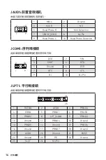
Page 14: ...ctor allows you to connect the optional serial port with bracket 1 2 10 9 1 DCD 2 SIN 3 SOUT 4 DTR 5 Ground 6 DSR 7 RTS 8 CTS 9 RI 10 No Pin 1 2 26 25 1 RSTB 2 AFD 3 PRND0 4 ERR 5 PRND1 6 PINIT 7 PRND...

Page 15: ...n below to adjust the fan connector to PWM or DC Mode PWM Mode pin definition 1 Ground 2 12V 3 Sense 4 Speed Control Signal DC Mode pin definition 1 Ground 2 Voltage Control 3 Sense 4 NC Default PWM M...

Page 16: ...r is for TPM Trusted Platform Module Please refer to the TPM security platform manual for more details and usages 1 2 14 13 1 LPC Clock 2 3V Standby power 3 LPC Reset 4 3 3V Power 5 LPC address data p...

Page 17: ...n Connector This connector allows you to connect the chassis intrusion switch cable Normal default Trigger the chassis intrusion event Using chassis intrusion detector 1 Connect the JCI1 connector to...

Page 18: ...wing methods to enter BIOS setup y Press Delete key when the Press DEL key to enter Setup Menu F11 to enter Boot Menu message appears on the screen during the boot process y Use MSI FAST BOOT applicat...

Page 19: ...e BIOS Setup during POST 2 Insert the USB flash drive that contains the update file into the computer 3 Select the M FLASH tab and click on Yes to reboot the system and enter the flash mode 4 Select a...

Page 20: ...Driver Disc into your optical drive 3 The installer will automatically appear and it will find and list all necessary drivers 4 Click Install button 5 The software installation will then be in progre...

Page 21: ...s 11 M2_1 M 2 Key M 12 ATX_PWR1 CPU_PWR1 12 JUSB1 JUSB2 USB 2 0 13 JUSB3 USB 3 1 Gen1 13 JAUD1 14 JCOM1 14 JLPT1 14 CPU_FAN1 SYS_FAN1 2 15 JTPM1 TPM 16 JTBT1 16 EZ LED 16 JCI1 17 JBAT1 CMOS Reset BIO...

Page 22: ...2 y ESD y y y ESD ESD y y y y y y y y PSU PSU y y y y 60 C 140 F...

Page 23: ...msi com y PCIe 3 0 x16 1 y PCIe 3 0 x1 2 y VGA 1 2048x1536 50Hz 2048x1280 60Hz 1920x1200 60Hz y DVI D 1 1920x1200 60Hz y HDMI 1 4096x2160 30Hz Intel B360 y SATA 6Gb s 6 y M 2 1 Key M PCIe 3 0 x4 SATA...

Page 24: ...HD LAN Realtek 8111H Gigabit LAN 1 y PS 2 1 y PS 2 1 y VGA 1 y DVI D 1 y HDMI 1 y LAN RJ45 1 y USB 2 0 A 2 y USB 3 1 Gen1 A 3 y USB 3 1 Gen1 C 1 y 3 y 24 ATX 1 y 8 ATX 12V 1 y SATA 6Gb s 6 y USB 3 1 G...

Page 25: ...5 I O NUVOTON NCT6797D y CPU y CPU y CPU y m ATX y 9 6 in x 9 6 in 24 4 cm x 24 4 cm BIOS y 1x 128 Mb 1 y UEFI AMI BIOS y ACPI 6 1 SM BIOS 2 8 y y y y y y 6 y y y DPC y y X y y CPU Z MSI y y y...

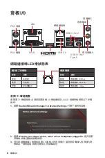
Page 26: ...1 USB 2 0 USB 3 1 Gen1 Type C Line Mic Line LAN LED Audio 7 1 7 1 I O JAUD1 1 Realtek HD Audio Manager Realtek HD Advanced Settings 2 Mute the rear output device when a front headphone plugged in 3 I...

Page 27: ...PCI_E3 ATX_PWR1 JUSB1 JUSB2 JUSB3 JBAT1 SATA 1 2 M2_1 JCI1 JFP1 SATA4 SATA5 SATA6 SATA3 JTBT1 JFP2 JAUD1 JLPT1 JCOM1 CPU Socket CPU_PWR1 DIMMA1 DIMMB1 DIMMB2 DIMMA2 SYS_FAN2 SYS_FAN1 CPU_FAN1 EZ Debug...

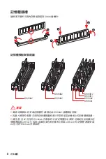
Page 28: ...8 I O DIMM DIMM y DIMMA2 y y 4GB 32 Windows OS 4GB 64 Windows OS 1 1 2 3 3 2 DIMMB2 DIMMB2 DIMMB1 DIMMA2 DIMMA2 DIMMA2 DIMMA1...

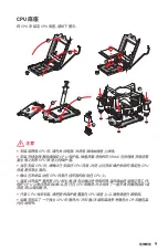
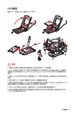
Page 29: ...9 I O CPU CPU CPU y CPU y CPU CPU MSI RMA y CPU CPU CPU y CPU y CPU CPU CPU y CPU CPU y CPU 1 4 6 5 7 8 9 3 2...

Page 30: ...10 I O PCI_E1 3 PCIe PCI_E1 PCIe 3 0 x16 CPU PCI_E3 PCIe 3 0 x1 slot PCH PCI_E2 PCIe 3 0 x1 slot PCH y MSI Gaming Series Graphics Card Bolster y PCIe x16 PCI_E1 y...

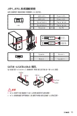
Page 31: ...0 y SATA JFP1 JFP2 LED 1 2 10 9 JFP1 1 HDD LED 2 Power LED 3 HDD LED 4 Power LED 5 Reset Switch 6 Power Switch 7 Reset Switch 8 Power Switch 9 Reserved 10 No Pin 1 JFP2 1 Speaker 2 Buzzer 3 Buzzer 4 S...

Page 32: ...und 15 Ground 4 5V 16 PS ON 5 Ground 17 Ground 6 5V 18 Ground 7 Ground 19 Ground 8 PWR OK 20 Res 9 5VSB 21 5V 10 12V 22 5V 11 12V 23 5V 12 3 3V 24 Ground 5 4 1 8 CPU_PWR1 1 Ground 5 12V 2 Ground 6 12V...

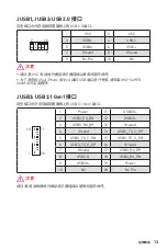
Page 33: ...Ground 14 USB3_TX_C_DP 5 USB3_TX_C_DN 15 USB3_TX_C_DN 6 USB3_TX_C_DP 16 Ground 7 Ground 17 USB3_RX_DP 8 USB2 0 18 USB3_RX_DN 9 USB2 0 19 Power 10 NC 20 No Pin JUSB1 JUSB2 USB 2 0 USB 2 0 1 2 10 9 1 VC...

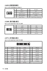
Page 34: ...Detection JCOM1 1 2 10 9 1 DCD 2 SIN 3 SOUT 4 DTR 5 Ground 6 DSR 7 RTS 8 CTS 9 RI 10 No Pin 1 2 26 25 1 RSTB 2 AFD 3 PRND0 4 ERR 5 PRND1 6 PINIT 7 PRND2 8 LPT_SLIN 9 PRND3 10 Ground 11 PRND4 12 Groun...

Page 35: ...Width Modulation DC PWM 12V DC PWM 3 Non PWM 100 PWM DC PWM 1 Ground 2 12V 3 Sense 4 Speed Control Signal DC 1 Ground 2 Voltage Control 3 Sense 4 NC PWM DC PWM DC BIOS Hardware Monitor PWM DC PWM DC...

Page 36: ...1 2 14 13 1 LPC Clock 2 3V Standby power 3 LPC Reset 4 3 3V Power 5 LPC address data pin0 6 Serial IRQ 7 LPC address data pin1 8 5V Power 9 LPC address data pin2 10 No Pin 11 LPC address data pin3 12...

Page 37: ...2 JBAT1 5 10 3 JBAT1 4 JCI1 Trigger the chassis intrusion event 1 JCI1 2 3 BIOS Security Chassis Intrusion Configuration 4 Chassis Intrusion Enabled 5 F10 Enter Yes 6 1 BIOS Security Chassis Intrusion...

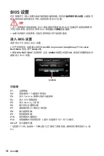
Page 38: ...BIOS BIOS HELP y BIOS BIOS y Press DEL key to enter Setup Menu F11 to enter Boot Menu DEL F11 Delete y MSI FAST BOOT GO2BIOS OK BIOS GO2BIOS F1 F2 F3 F4 CPU F5 Memory Z F6 F7 EZ F8 F9 F10 F12 USB FAT...

Page 39: ...CMOS BIOS CMOS BIOS M FLASH BIOS BIOS MSI BIOS USB BIOS 1 POST Del BIOS 2 USB 3 M FLASH Yes 4 BIOS BIOS 5 100 Live Update 6 BIOS LAN BIOS 1 MSI LIVE UPDATE 6 2 BIOS Update 3 Scan 4 Download BIOS 5 Nex...

Page 40: ...Windows 10 1 2 Windows 10 3 Restart 4 POST Power On Self Test F11 5 6 Press any key to boot from CD or DVD 7 Windows 10 1 Windows 10 2 MSI 3 4 Install 5 6 OK 7 1 MSI 2 3 Utilities 4 5 Install 6 7 OK...

Page 41: ...de port s rie 14 JLPT1 Connecteur de port parall le 14 CPU_FAN1 SYS_FAN1 2 Connecteurs pour ventilateurs 15 JTPM1 Connecteur de module TPM 16 JTBT1 Connecteur de carte additionnelle Thunderbolt 16 EZ...

Page 42: ...ien fix s sur la carte m re ou ailleurs dans le bo tier de l ordinateur y Ne d marrez pas l ordinateur avant d avoir termin l installation Ceci peut endommager les composants ou vous blesser y Si vous...

Page 43: ...z 2048x1280 60Hz 1920x1200 60Hz y 1 x port DVI D supportant une r solution maximum de 1920x1200 60Hz y 1 x port HDMI 1 4 supportant une r solution maximum de 4096x2160 30Hz Stockage Chipset Intel B360...

Page 44: ...port LAN RJ45 y 2 x ports USB 2 0 Type A y 3 x ports USB 3 1 Gen1 Type A y 1 x port USB 3 1 Gen1 Type C y 3 x jacks audio Connecteurs internes y 1 x connecteur d alimentation principal ATX 24 broches...

Page 45: ...r du CPU et du syst me Dimensions y Format m ATX y 24 4 cm x 24 4 cm 9 6 x 9 6 Fonctions BIOS y 1 x flash BIOS 128 Mb y UEFI AMI BIOS y ACPI 6 1 SM BIOS 2 8 y Multilingue Logiciel y Pilotes y APP MANA...

Page 46: ...uration audio 7 1 canal Pour r gler le syst me audio 7 1 connectez le module audio entr e sortie du panneau avant au connecteur JAUD1 et suivez les tapes ci dessous 1 Cliquez sur Realtek HD Audio Mana...

Page 47: ...I_E1 PCI_E2 JTPM1 PCI_E3 ATX_PWR1 JUSB1 JUSB2 JUSB3 JBAT1 SATA 1 2 M2_1 JCI1 JFP1 SATA4 SATA5 SATA6 SATA3 JTBT1 JFP2 JAUD1 JLPT1 JCOM1 CPU_PWR1 DIMMA1 DIMMB1 DIMMB2 DIMMA2 SYS_FAN2 SYS_FAN1 CPU_FAN1 E...

Page 48: ...t la capacit de m moire disponible est un peu moins lev e que celle install e y Veuillez noter que la capacite maximum de la memoire est de 4 Go ou moins pour le systeme d exploitation Windows 32 bit...

Page 49: ...contre la surchauffe et maintenir la stabilit du syst me y Assurez vous de l tanch it entre le ventilateur et le processeur avant de d marrer votre syst me y La surchauffe peut facilement endommager...

Page 50: ...ort MSI Gaming Series pour supporter son poids et pour viter la d formation du slot y Si vous choisissez d installer une seule carte d extension PCIe x16 nous vous recommandons d utiliser le slot PCI_...

Page 51: ...c ble SATA dispose de prises identiques sur chaque c t N anmoins il est recommand de connecter la prise plate sur la carte m re pour un gain d espace JFP1 JFP2 Connecteurs de panneau avant Ces connect...

Page 52: ...5 Ground 17 Ground 6 5V 18 Ground 7 Ground 19 Ground 8 PWR OK 20 Res 9 5VSB 21 5V 10 12V 22 5V 11 12V 23 5V 12 3 3V 24 Ground 5 4 1 8 CPU_PWR1 1 Ground 5 12V 2 Ground 6 12V 3 Ground 7 12V 4 Ground 8...

Page 53: ...Important Notez que les c bles d alimentation et de terre doivent tre branch s correctement afin d viter d endommager la carte JUSB1 JUSB2 Connecteurs USB 2 0 Ces connecteurs vous permettent de relie...

Page 54: ...e Ce connecteur vous permet de relier un port s rie en option 1 2 10 9 1 DCD 2 SIN 3 SOUT 4 DTR 5 Ground 6 DSR 7 RTS 8 CTS 9 RI 10 No Pin 1 2 26 25 1 RSTB 2 AFD 3 PRND0 4 ERR 5 PRND1 6 PINIT 7 PRND2 8...

Page 55: ...tilateur en mode PWM ou mode DC D finition des broches en mode PWM 1 Ground 2 12V 3 Sense 4 Speed Control Signal D finition des broches en mode DC 1 Ground 2 Voltage Control 3 Sense 4 NC Connecteurs p...

Page 56: ...initialisation a chou JTPM1 Connecteur de module TPM Ce connecteur est reli un module TPM Trusted Platform Module Veuillez vous r f rer au manuel du module TPM pour plus d informations 1 2 14 13 1 LPC...

Page 57: ...ur est reli un c ble d interrupteur intrusion ch ssis Normal d faut Commencer l activit intrusion ch ssis Utilisation du d tecteur d intrusion ch ssis 1 Reliez le connecteur JCI1 l interrupteur ou au...

Page 58: ...ant le d marrage lorsqu appara t le message Press DEL key to enter Setup Menu F11 to enter Boot Menu sur l cran veuillez appuyer sur la touche Suppr y Quand l ordinateur est d j en marche vous pouvez...

Page 59: ...ur 1 Appuyez sur la touche Suppr pour entrer dans l interface Setup du BIOS pendant le processus de POST 2 Connectez le lecteur Flash USB contenant le profil l ordinateur 3 Choisissez l onglet M FLASH...

Page 60: ...Disc dans le lecteur optique 3 L outil d installation appara t automatiquement Il trouvera et listera tous les pilotes dont vous avez besoin 4 Cliquez sur le bouton Install 5 L installation des pilote...

Page 61: ...Anschluss 15 JLPT1 Parallele Schnittstelle 15 CPU_FAN1 SYS_FAN1 2 Stromanschl sse f r L fter 16 JTPM1 TPM Anschluss 17 JTBT1 Anschluss f r Thunderbolt Erweiterungskarte 17 EZ Debug LED 17 JCI1 Geh us...

Page 62: ...er nicht bevor die Installation abgeschlossen ist Dies k nnte permanente Sch den an den Komponenten sowie zu das Verletzung des Benutzers verursachen y Sollten Sie Hilfe bei der Installation ben tigen...

Page 63: ...0Hz 2048x1280 60Hz 1920x1200 60Hz y 1x DVI D Anschluss Unterst tzung einer maximalen Aufl sung von 1920x1200 60Hz y 1x HDMI Anschluss 1 4 Unterst tzung einer maximalen Aufl sung von 4096x2160 30Hz Auf...

Page 64: ...der r ckseitigen Anschlussleiste 4 Anschl sse stehen durch die internen USB Anschluss zur Verf gung Audio y Realtek ALC887 Codec y 7 1 Kanal HD Audio LAN 1x Realtek 8111H Gigabit LAN Controller Hinter...

Page 65: ...uss des Frontpanels y 1x Parallele Schnittstelle y 1x Serieller Anschluss y 2x Frontpanel Anschl sse y 1x TPM Anschluss y 1x Geh usekontaktschalter y 1x Anschluss f r Thunderbolt Erweiterungskarte y 1...

Page 66: ...APP MANAGER y SUPER CHARGER y COMMAND CENTER y LIVE UPDATE 6 y SMART TOOL y RAMDISK y DPC LATENCY TUNER y FAST BOOT y X BOOST y MYSTIC LIGHT y CPU Z MSI GAMING y Intel Extreme Tuning Utility y Google...

Page 67: ...ion Um 7 1 Kanal Audio zu konfigurieren m ssen Sie den Front Audio Anschluss mit dem JAUD1 Anschluss verbinden und folgen Sie die untenstehenden Schritten 1 Klicken Sie auf Realtek HD Audio Manager Ad...

Page 68: ...E3 ATX_PWR1 JUSB1 JUSB2 JUSB3 JBAT1 SATA 1 2 M2_1 JCI1 JFP1 SATA4 SATA5 SATA6 SATA3 JTBT1 JFP2 JAUD1 JLPT1 JCOM1 CPU Socket CPU_PWR1 DIMMA1 DIMMB1 DIMMB2 DIMMA2 SYS_FAN2 SYS_FAN1 CPU_FAN1 EZ Debug LED...

Page 69: ...wird die verf gbare Kapazit t des Speichers kleiner sein als die Gr e der installierten Speicherkapazit t y Bitte beachten Sie dass die maximale Kapazit t eines 32 Bit Windows Betriebssystem bei 4GB o...

Page 70: ...ermeiden und die Systemstabilit t zu gew hrleisten y Stellen Sie sicher dass Ihr K hlk rper eine feste Verbindung mit der CPU hergestellt hat bevor Sie Ihr System starten y berhitzung besch digt die C...

Page 71: ...as Gewicht tr gt und eine Verformung des Steckplatzes vermeidet y F r die Installation einer einzelnen PCIe x16 Erweiterungskarte mit optimaler Leistung empfehlen wir den PCI_E1 Steckplatz zu verwende...

Page 72: ...e die Folge sein y SATA Kabel haben identische Stecker an beiden Enden Es wird empfohlen den flachen Stecker auf dem Motherboard einstecken JFP1 JFP2 Frontpanel Anschl sse Diese Anschl sse verbinden m...

Page 73: ...ON 5 Ground 17 Ground 6 5V 18 Ground 7 Ground 19 Ground 8 PWR OK 20 Res 9 5VSB 21 5V 10 12V 22 5V 11 12V 23 5V 12 3 3V 24 Ground 5 4 1 8 CPU_PWR1 1 Ground 5 12V 2 Ground 6 12V 3 Ground 7 12V 4 Ground...

Page 74: ...e die mit Stromf hrende Leitung und Erdleitung bezeichneten Pins korrekt verbinden m ssen ansonsten kann es zu Sch den kommen JUSB1 JUSB2 USB 2 0 Anschl sse Mit diesen Anschl ssen k nnen Sie die USB 2...

Page 75: ...nnen Sie das optionale serielle Schnittstelle mit dem Einbausatze verbinden 1 2 10 9 1 DCD 2 SIN 3 SOUT 4 DTR 5 Ground 6 DSR 7 RTS 8 CTS 9 RI 10 No Pin 1 2 26 25 1 RSTB 2 AFD 3 PRND0 4 ERR 5 PRND1 6...

Page 76: ...den Anweisungen um den PWM oder DC Modus auszuw hlen Pin Belegung des PWM Modus 1 Ground 2 12V 3 Sense 4 Speed Control Signal Pin Belegung des DC Modus 1 Ground 2 Voltage Control 3 Sense 4 NC L fteran...

Page 77: ...tform Module verwendet Weitere Informationen ber den Einsatz des optionalen TPM Modules entnehmen Sie bitte dem TPM Plattform Handbuch 1 2 14 13 1 LPC Clock 2 3V Standby power 3 LPC Reset 4 3 3V Power...

Page 78: ...schalten Sie den Computer ein JCI1 Geh usekontaktanschluss Dieser Anschluss wird mit einem Kontaktschalter verbunden Normal Standardwert L se den Geh useeingriff aus Geh usekontakt Detektor verwenden...

Page 79: ...aufzurufen y W hrend des BOOT Vorgangs dr cken Sie die Taste ENTF wenn die Meldung Press DEL key to enter Setup Menu F11 to enter Boot Menu erscheint y Verwenden Sie die MSI FAST BOOT Anwendung Klicke...

Page 80: ...ngs die Taste Entf um das BIOS zu ffnen 2 Schlie en das USB Flashlaufwerk mit der BIOS Datei an den Computer 3 W hlen Sie die Registerkarte M FLASH und klicken Sie auf Yes Ja um das System neu zu star...

Page 81: ...sches Laufwerk 3 Der Installer wird automatisch erscheint und findet und finden Sie die ben tigten Treiber in die Liste 4 Klicken Sie auf Install 5 Die Software Installation ist im Gange Wenn die Inst...

Page 82: ...22 Softwarebeschreibung NOTE...

Page 83: ...2_1 M 2 M 12 ATX_PWR1 CPU_PWR1 12 JUSB1 JUSB2 USB 2 0 13 JUSB3 USB 3 1 Gen1 13 JAUD1 14 JCOM1 14 JLPT1 14 CPU_FAN1 SYS_FAN1 2 15 JTPM1 TPM 16 JTBT1 Thunderbolt 16 EZ 16 JCI1 17 JBAT1 CMOS BIOS 17 BIOS...

Page 84: ...2 y y y y y y y y y y y y y y y y 60 C 140 F...

Page 85: ...e XMP www msi com y 1x PCIe 3 0 x16 y 2x PCIe 3 0 x1 y 1x VGA 2048x1536 50 2048x1280 60 1920x1200 60 y 1x DVI D 1920x1200 60 y 1x HDMI 1 4 4096x2160 30 Intel B360 y 6x SATA 6 y 1x M 2 M PCIe 3 0 x4 SA...

Page 86: ...h Definition Audio LAN 1x Realtek 8111H y 1x PS 2 y 1x PS 2 y 1x VGA y 1x DVI D y 1x HDMI y 1x LAN RJ45 y 2x USB 2 0 Type A y 3x USB 3 1 Gen1 Type A y 1x USB 3 1 Gen1 Type C y 3x y 1x 24 ATX y 1x 8 AT...

Page 87: ...6 1 SM BIOS 2 8 y y y APP MANAGER y SUPER CHARGER y COMMAND CENTER y LIVE UPDATE 6 y SMART TOOL y RAMDISK y DPC LATENCY TUNER y FAST BOOT y X BOOST y MYSTIC LIGHT y CPU Z MSI GAMING y Intel Extreme T...

Page 88: ...100 1 LAN PS 2 PS 2 LAN DVI D VGA USB 3 1 Gen1 USB 2 0 USB 3 1 Gen1 Type C Audio 7 1 7 1 JAUD1 1 Realtek HD Audio Manager Advanced Settings 2 Mute the rear output device when a front headphone plugged...

Page 89: ...2 JTPM1 PCI_E3 ATX_PWR1 JUSB1 JUSB2 JUSB3 JBAT1 SATA 1 2 M2_1 JCI1 JFP1 SATA4 SATA5 SATA6 SATA3 JTBT1 JFP2 JAUD1 JLPT1 JCOM1 CPU_PWR1 DIMMA1 DIMMB1 DIMMB2 DIMMA2 SYS_FAN2 SYS_FAN1 CPU_FAN1 EZ Debug LE...

Page 90: ...8 DIMM DIMM y DIMMA2 y y 32 Windows 4 4 64 Windows 1 1 2 3 3 2 DIMMB2 DIMMB2 DIMMB1 DIMMA2 DIMMA2 DIMMA2 DIMMA1...

Page 91: ...9 y y MSI y y y y y 1 4 6 5 7 8 9 3 2...

Page 92: ...10 PCI_E1 3 PCIe PCI_E1 PCIe 3 0 x16 CPU PCI_E3 PCIe 3 0 x1 PCH PCI_E2 PCIe 3 0 x1 PCH y MSI Gaming Series Graphics Card Bolster y PCIe x16 PCI_E1 y...

Page 93: ...ATA JFP1 JFP2 1 2 10 9 JFP1 1 HDD LED 2 Power LED 3 HDD LED 4 Power LED 5 Reset Switch 6 Power Switch 7 Reset Switch 8 Power Switch 9 Reserved 10 No Pin 1 JFP2 1 Speaker 2 Buzzer 3 Buzzer 4 Speaker HD...

Page 94: ...Ground 15 Ground 4 5V 16 PS ON 5 Ground 17 Ground 6 5V 18 Ground 7 Ground 19 Ground 8 PWR OK 20 Res 9 5VSB 21 5V 10 12V 22 5V 11 12V 23 5V 12 3 3V 24 Ground 5 4 1 8 CPU_PWR1 1 Ground 5 12V 2 Ground 6...

Page 95: ...ound 14 USB3_TX_C_DP 5 USB3_TX_C_DN 15 USB3_TX_C_DN 6 USB3_TX_C_DP 16 Ground 7 Ground 17 USB3_RX_DP 8 USB2 0 18 USB3_RX_DN 9 USB2 0 19 Power 10 NC 20 No Pin JUSB1 JUSB2 USB 2 0 USB 2 0 1 2 10 9 1 VCC...

Page 96: ...etection JCOM1 1 2 10 9 1 DCD 2 SIN 3 SOUT 4 DTR 5 Ground 6 DSR 7 RTS 8 CTS 9 RI 10 No Pin 1 2 26 25 1 RSTB 2 AFD 3 PRND0 4 ERR 5 PRND1 6 PINIT 7 PRND2 8 LPT_SLIN 9 PRND3 10 Ground 11 PRND4 12 Ground...

Page 97: ...PulseWidth Modulation PWM 12 3 Non PWM PWM PWM DC PWM 1 Ground 2 12V 3 Sense 4 Speed Control Signal DC 1 Ground 2 Voltage Control 3 Sense 4 NC PWM DC BIOS HARDWARE MONITOR PWM DC PWM DC PWM DC 1 CPU_...

Page 98: ...3V Standby power 3 LPC Reset 4 3 3V Power 5 LPC address data pin0 6 Serial IRQ 7 LPC address data pin1 8 5V Power 9 LPC address data pin2 10 No Pin 11 LPC address data pin3 12 Ground 13 LPC Frame 14...

Page 99: ...OS BIOS 1 2 JBAT1 5 10 3 JBAT1 4 JCI1 1 JCI1 2 3 BIOS Security Chassis Intrusion Configuration 4 Chassis Intrusion Enabled 5 F10 Enter Yes 6 1 BIOS Security Chassis Intrusion Configuration 2 Chassis I...

Page 100: ...y BIOS BIOS BIOS HELP y BIOS BIOS y Delete Press DEL key to enter Setup Menu F11 to enter Boot Menu y MSI FAST BOOT GO2BIOS BIOS GO2BIOS F1 F2 F3 F4 F5 Memory Z F6 F7 EZ F8 F9 F10 F12 USB FAT FAT32 C...

Page 101: ...r CMOS CMOS BIOS CMOS BIOS BIOS M FLASH BIOS MSI BIOS USB BIOS 1 Del BIOS POST 2 USB 3 M FLASH Yes 4 BIOS BIOS 5 BIOS Live Update 6 BIOS 1 MSI LIVE UPDATE 6 2 BIOS Update 3 Scan 4 Download BIOS 5 Next...

Page 102: ...1 2 Windows 10 3 Restart 4 F11 POST Power On Self Test 5 6 Press any key to boot from CD or DVD 7 Windows 10 1 Windows 10 2 MSI Driver Disc 3 4 Install 5 6 OK 7 1 MSI Driver Disc 2 3 Utilities 4 5 Ins...

Page 103: ...s 11 M2_1 M 2 M Key 12 ATX_PWR1 CPU_PWR1 12 JUSB1 JUSB2 USB 2 0 13 JUSB3 USB 3 1 Gen1 13 JAUD1 14 JCOM1 14 JLPT1 14 CPU_FAN1 SYS_FAN1 2 15 JTPM1 TPM 16 JTBT1 Thunderbolt 16 LED 16 JCI1 17 JBAT1 CMOS B...

Page 104: ...2 y ESD y y y ESD ESD y y y y y y y y y y y y 60 140...

Page 105: ...XMP www msi com y 1 PCIe 3 0 x16 y 2 PCIe 3 0 x1 y 1 VGA 2048x1536 50Hz 2048x1280 60Hz 1920x1200 60Hz y 1 DVI D 1920x1200 60Hz y 1 HDMI 1 4 4096x2160 30Hz Intel B360 y 6 SATA 6Gb s y 1 M 2 M Key PCIe...

Page 106: ...7 1 LAN 1 Realtek 8111H y 1 PS 2 y 1 PS 2 y 1 VGA y 1 DVI D y 1 HDMI y 1 LAN RJ45 y 2 USB 2 0 Type A y 3 USB 3 1 Gen1 Type A y 1 USB 3 1 Gen1 Type C y 3 y 1 24 pin ATX y 1 8 pin ATX 12V y 6 SATA 6Gb s...

Page 107: ...CPU y CPU y CPU y m ATX y 9 6 x 9 6 24 4 x 24 4 BIOS y 1 128 Mb flash y UEFI AMI BIOS y ACPI 6 1 SM BIOS 2 8 y y y APP y y COMMAND CENTER y LIVE UPDATE 6 y y y DPC y y y RGB LED y MSI GAMING CPU Z y...

Page 108: ...0 Mbps 1 Gbps LAN LED PS 2 PS 2 LAN DVI D VGA USB 3 1 Gen1 USB 2 0 USB 3 1 Gen1 Type C 7 1 7 1 I O JAUD1 1 Realtek HD Audio Manager Advanced Settings 2 Mute the rear output device when a front headpho...

Page 109: ...E1 PCI_E2 JTPM1 PCI_E3 ATX_PWR1 JUSB1 JUSB2 JUSB3 JBAT1 SATA 1 2 M2_1 JCI1 JFP1 SATA4 SATA5 SATA6 SATA3 JTBT1 JFP2 JAUD1 JLPT1 JCOM1 CPU_PWR1 DIMMA1 DIMMB1 DIMMB2 DIMMA2 SYS_FAN2 SYS_FAN1 CPU_FAN1 50...

Page 110: ...8 DIMM DIMM y DIMMA2 y y 32 Windows 4GB 4GB 64 Windows 1 1 2 3 3 2 DIMMB2 DIMMB2 DIMMB1 DIMMA2 DIMMA2 DIMMA2 DIMMA1...

Page 111: ...9 CPU CPU CPU y CPU y CPU RMA CPU y CPU CPU CPU y CPU CPU y CPU CPU CPU y CPU CPU y CPU 1 4 6 5 7 8 9 3 2...

Page 112: ...10 PCI_E1 3 PCIe PCI_E1 PCIe 3 0 x16 CPU PCI_E3 PCIe 3 0 x1 PCH PCI_E2 PCIe 3 0 x1 PCH y MSI y PCIe x16 PCI_E1 y...

Page 113: ...y SATA JFP1 JFP2 LED 1 2 10 9 JFP1 1 HDD LED 2 Power LED 3 HDD LED 4 Power LED 5 Reset Switch 6 Power Switch 7 Reset Switch 8 Power Switch 9 Reserved 10 No Pin 1 JFP2 1 Speaker 2 Buzzer 3 Buzzer 4 Spe...

Page 114: ...12V 3 Ground 15 Ground 4 5V 16 PS ON 5 Ground 17 Ground 6 5V 18 Ground 7 Ground 19 Ground 8 PWR OK 20 Res 9 5VSB 21 5V 10 12V 22 5V 11 12V 23 5V 12 3 3V 24 Ground 5 4 1 8 CPU_PWR1 1 Ground 5 12V 2 Gro...

Page 115: ...ound 14 USB3_TX_C_DP 5 USB3_TX_C_DN 15 USB3_TX_C_DN 6 USB3_TX_C_DP 16 Ground 7 Ground 17 USB3_RX_DP 8 USB2 0 18 USB3_RX_DN 9 USB2 0 19 Power 10 NC 20 No Pin JUSB1 JUSB2 USB 2 0 USB 2 0 1 2 10 9 1 VCC...

Page 116: ...etection JCOM1 1 2 10 9 1 DCD 2 SIN 3 SOUT 4 DTR 5 Ground 6 DSR 7 RTS 8 CTS 9 RI 10 No Pin 1 2 26 25 1 RSTB 2 AFD 3 PRND0 4 ERR 5 PRND1 6 PINIT 7 PRND2 8 LPT_SLIN 9 PRND3 10 Ground 11 PRND4 12 Ground...

Page 117: ...2 PWM DC PWM 12V DC 3 PWM PWM 100 PWM DC PWM 1 Ground 2 12V 3 Sense 4 Speed Control Signal DC 1 Ground 2 Voltage Control 3 Sense 4 NC PWM DC PWM DC BIOS HARDWARE MONITOR PWM DC PWM DC CPU 1 CPU_FAN1 1...

Page 118: ...Standby power 3 LPC Reset 4 3 3V Power 5 LPC address data pin0 6 Serial IRQ 7 LPC address data pin1 8 5V Power 9 LPC address data pin2 10 No Pin 11 LPC address data pin3 12 Ground 13 LPC Frame 14 Grou...

Page 119: ...BIOS BIOS 1 2 JBAT1 5 10 3 JBAT1 4 JCI1 1 JCI1 2 3 BIOS Security Chassis Intrusion Configuration 4 Chassis Intrusion Enabled 5 F10 Enter Yes 6 1 BIOS Security Chassis Intrusion Configuration 2 Chassi...

Page 120: ...BIOS BIOS y BIOS BIOS y Press DEL key to enter Setup Menu F11 to enter Boot Menu Delete y MSI FAST BOOT GO2BIOS OK BIOS GO2BIOS F1 F2 F3 Favorites F4 CPU F5 Memory Z F6 F7 EZ F8 F9 F10 F12 U FAT FAT3...

Page 121: ...MOS CMOS BIOS BIOS M FLASH BIOS MSI BIOS BIOS U BIOS 1 POST Del BIOS 2 U 3 M FLASH Yes flash 4 BIOS BIOS 5 100 Live Update 6 BIOS LAN BIOS 1 MSI LIVE UPDATE 6 2 BIOS Update 3 Scan 4 Download BIOS 5 Ne...

Page 122: ...20 Windows 10 1 2 Windows 10 3 Restart 4 POST F11 5 6 Press any key to boot from CD or DVD 7 Windows 10 1 Windows 10 2 MSI 3 4 Install 5 6 OK 7 1 MSI 2 3 Utilities 4 5 Install 6 7 OK 8...

Page 123: ...M2_1 M 2 M Key 12 ATX_PWR1 CPU_PWR1 12 JUSB1 JUSB2 USB 2 0 13 JUSB3 USB 3 1 Gen1 13 JAUD1 14 JCOM1 14 JLPT1 14 CPU_FAN1 SYS_FAN1 2 15 JTPM1 TPM 16 JTBT1 Thunderbolt 16 LED 16 JCI1 17 JBAT1 CMOS BIOS 1...

Page 124: ...2 y ESD y y y y y y y y y y y y y y y 60 C 140 F...

Page 125: ...w msi com y 1 PCIe 3 0 x16 y 2 PCIe 3 0 x1 y 1 VGA 2048x1536 50Hz 2048x1280 60Hz 1920x1200 60Hz y 1 DVI D 1920x1200 60Hz y 1 HDMI 1 4 4096x2160 30Hz Intel B360 y 6 SATA 6Gb s y 1 M 2 M Key PCIe 3 0 x4...

Page 126: ...1 1 Realtek 8111H Gigabit y 1 PS 2 y 1 PS 2 y 1 VGA y 1 DVI D y 1 HDMI y 1 LAN RJ45 y 2 USB 2 0 Type A y 3 USB 3 1 Gen1 Type A y 1 USB 3 1 Gen1 Type C y 3 y 1 24 pin ATX y 1 8 pin ATX 12V y 6 SATA 6Gb...

Page 127: ...sh y UEFI AMI BIOS y ACPI 6 1 SM BIOS 2 8 y y y y SUPER CHARGER y COMMAND CENTER y LIVE UPDATE 6 y SMART TOOL y RAMDISK y DPC LATENCY TUNER y FAST BOOT y X BOOST y MYSTIC LIGHT y CPU Z MSI GAMING y In...

Page 128: ...s 100 Mbps 1 Gbps LED PS 2 PS 2 DVI D VGA USB 3 1 Gen1 USB 2 0 USB 3 1 Gen1 Type C 7 1 7 1 I O JAUD1 1 Realtek HD Audio Manager Advanced Settings 2 Mute the rear output device when a front headphone p...

Page 129: ...2 JTPM1 PCI_E3 ATX_PWR1 JUSB1 JUSB2 JUSB3 JBAT1 SATA 1 2 M2_1 JCI1 JFP1 SATA4 SATA5 SATA6 SATA3 JTBT1 JFP2 JAUD1 JLPT1 JCOM1 CPU_PWR1 DIMMA1 DIMMB1 DIMMB2 DIMMA2 SYS_FAN2 SYS_FAN1 CPU_FAN1 EZ Debug LE...

Page 130: ...8 DIMM y DIMMA2 y y 32 Windows 4GB 4GB 64 Windows 1 1 2 3 3 2 DIMMB2 DIMMB2 DIMMB1 DIMMA2 DIMMA2 DIMMA2 DIMMA1...

Page 131: ...9 CPU CPU CPU y y CPU CPU Return Merchandise Authorization RMA y CPU CPU y CPU y CPU CPU CPU y CPU CPU y 1 4 6 5 7 8 9 3 2...

Page 132: ...10 PCI_E1 3 PCIe PCI_E1 PCIe 3 0 x16 CPU lanes PCI_E3 PCIe 3 0 x1 slot PCH lanes PCI_E2 PCIe 3 0 x1 slot PCH lanes y MSI Gaming Series y PCIe x16 PCI_E1 y...

Page 133: ...y SATA JFP1 JFP2 LED 1 2 10 9 JFP1 1 HDD LED 2 Power LED 3 HDD LED 4 Power LED 5 Reset Switch 6 Power Switch 7 Reset Switch 8 Power Switch 9 Reserved 10 No Pin 1 JFP2 1 Speaker 2 Buzzer 3 Buzzer 4 Spe...

Page 134: ...15 Ground 4 5V 16 PS ON 5 Ground 17 Ground 6 5V 18 Ground 7 Ground 19 Ground 8 PWR OK 20 Res 9 5VSB 21 5V 10 12V 22 5V 11 12V 23 5V 12 3 3V 24 Ground 5 4 1 8 CPU_PWR1 1 Ground 5 12V 2 Ground 6 12V 3...

Page 135: ...ound 14 USB3_TX_C_DP 5 USB3_TX_C_DN 15 USB3_TX_C_DN 6 USB3_TX_C_DP 16 Ground 7 Ground 17 USB3_RX_DP 8 USB2 0 18 USB3_RX_DN 9 USB2 0 19 Power 10 NC 20 No Pin JUSB1 JUSB2 USB 2 0 USB 2 0 1 2 10 9 1 VCC...

Page 136: ...etection JCOM1 1 2 10 9 1 DCD 2 SIN 3 SOUT 4 DTR 5 Ground 6 DSR 7 RTS 8 CTS 9 RI 10 No Pin 1 2 26 25 1 RSTB 2 AFD 3 PRND0 4 ERR 5 PRND1 6 PINIT 7 PRND2 8 LPT_SLIN 9 PRND3 10 Ground 11 PRND4 12 Ground...

Page 137: ...2 PWM DC PWM 12V DC 3 PWM PWM 100 PWM DC PWM 1 Ground 2 12V 3 Sense 4 Speed Control Signal DC 1 Ground 2 Voltage Control 3 Sense 4 NC PWM DC PWM DC BIOS HARDWARE MONITOR PWM DC PWM DC CPU 1 CPU_FAN1 1...

Page 138: ...dby power 3 LPC Reset 4 3 3V Power 5 LPC address data pin0 6 Serial IRQ 7 LPC address data pin1 8 5V Power 9 LPC address data pin2 10 No Pin 11 LPC address data pin3 12 Ground 13 LPC Frame 14 Ground J...

Page 139: ...BIOS BIOS 1 2 JBAT1 5 10 3 JBAT1 4 JCI1 1 JCI1 2 3 BIOS Security Chassis Intrusion Configuration 4 Chassis Intrusion Enabled 5 F10 Enter Yes 6 1 BIOS Security Chassis Intrusion Configuration 2 Chassi...

Page 140: ...18 BIOS BIOS BIOS y BIOS BIOS HELP BIOS y BIOS BIOS y DEL F11 Boot Menu Delete y MSI FAST BOOT GO2BIOS BIOS GO2BIOS F1 F2 F3 F4 CPU F5 Memory Z F6 F7 EZ F8 F9 F10 F12 USB FAT FAT32 Ctrl F F10...

Page 141: ...S CMOS CMOS BIOS BIOS M FLASH BIOS MSI BIOS BIOS USB BIOS 1 POST Del BIOS 2 USB 3 M FLASH 4 BIOS BIOS 5 100 Live Update 6 BIOS BIOS 1 MSI LIVE UPDATE 6 2 BIOS Update BIOS 3 Scan 4 Download BIOS 5 Next...

Page 142: ...20 Windows 10 1 2 Windows 10 3 4 POST F11 5 6 Press any key to boot from CD or DVD 7 Windows 10 1 Windows 10 2 MSI 3 4 5 6 7 1 MSI 2 3 4 5 6 7 8...

Page 143: ...M2_1 M 2 Key M 12 ATX_PWR1 CPU_PWR1 12 JUSB1 JUSB2 USB 2 0 13 JUSB3 USB 3 1 Gen1 13 JAUD1 14 JCOM1 14 JLPT1 14 CPU_FAN1 SYS_FAN1 2 15 JTPM1 TPM 16 JTBT1 Thunderbolt 16 EZ Debug LED 16 JCI1 17 JBAT1 CM...

Page 144: ...2 y ESD PC y y y ESD ESD y y PC y PC y PC y PC PC y y y y y y PC y 60O C 140O F...

Page 145: ...ile XMP www msi com y PCIe 3 0 x16 x1 y PCIe 3 0 x1 x2 y VGA x1 2048x1536 50Hz 2048x1280 60Hz 1920x1200 60Hz y DVI D x1 1920x1200 60Hz y HDMI x1 4096x2160 30Hz Intel B360 y SATA 6Gb s x6 y M 2 x1 Key...

Page 146: ...Realtek 8111H Gigabit LAN x1 y PS 2 x1 y PS 2 x1 y VGA x1 y DVI D x1 y HDMI x1 y LAN RJ45 x1 y USB 2 0 Type A x2 y USB 3 1 Gen1 Type A x3 y USB 3 1 Gen1 Type C x1 y x3 y 24 ATX x1 y 8 ATX 12V x1 y SAT...

Page 147: ...EFI AMI BIOS y ACPI 6 1 SM BIOS 2 8 y y y APP MANAGER y SUPER CHARGER y COMMAND CENTER y LIVE UPDATE 6 y SMART TOOL y RAMDISK y DPC LATENCY TUNER y FAST BOOT y X BOOST y MYSTIC LIGHT y CPU Z MSI GAMIN...

Page 148: ...Mbps 100 Mbps 1 Gbps LAN LED PS 2 PS 2 LAN DVI D VGA USB 3 1 Gen1 USB 2 0 USB 3 1 Gen1 Type C 7 1 7 1 I O JAUD1 1 Realtek HD Audio Manager Advanced Settings 2 Mute the rear output device when a front...

Page 149: ...2 JTPM1 PCI_E3 ATX_PWR1 JUSB1 JUSB2 JUSB3 JBAT1 SATA 1 2 M2_1 JCI1 JFP1 SATA4 SATA5 SATA6 SATA3 JTBT1 JFP2 JAUD1 JLPT1 JCOM1 CPU_PWR1 DIMMA1 DIMMB1 DIMMB2 DIMMA2 SYS_FAN2 SYS_FAN1 CPU_FAN1 EZ Debug LE...

Page 150: ...8 I O DIMM DIMM y DIMMA2 y y 32bit Windows OS 4GB 4GB 64bit Windows OS 1 1 2 3 3 2 DIMMB2 DIMMB2 DIMMB1 DIMMA2 DIMMA2 DIMMA2 DIMMA1...

Page 151: ...9 I O CPU CPU CPU y CPU y CPU CPU CPU CPU CPU y CPU CPU CPU y CPU CPU y CPU CPU CPU CPU CPU y CPU CPU y CPU CPU CPU 1 4 6 5 7 8 9 3 2...

Page 152: ...10 I O PCI_E1 3 PCIe PCI_E1 PCIe 3 0 x16 CPU PCI_E3 PCIe 3 0 x1 slot PCH PCI_E2 PCIe 3 0 x1 slot PCH y MSI Gaming Series Graphics Card Bolster y PCIe x16 PCI_E1 y...

Page 153: ...0 y SATA JFP1 JFP2 LED 1 2 10 9 JFP1 1 HDD LED 2 Power LED 3 HDD LED 4 Power LED 5 Reset Switch 6 Power Switch 7 Reset Switch 8 Power Switch 9 Reserved 10 No Pin 1 JFP2 1 Speaker 2 Buzzer 3 Buzzer 4 S...

Page 154: ...3 Ground 15 Ground 4 5V 16 PS ON 5 Ground 17 Ground 6 5V 18 Ground 7 Ground 19 Ground 8 PWR OK 20 Res 9 5VSB 21 5V 10 12V 22 5V 11 12V 23 5V 12 3 3V 24 Ground 5 4 1 8 CPU_PWR1 1 Ground 5 12V 2 Ground...

Page 155: ...Ground 14 USB3_TX_C_DP 5 USB3_TX_C_DN 15 USB3_TX_C_DN 6 USB3_TX_C_DP 16 Ground 7 Ground 17 USB3_RX_DP 8 USB2 0 18 USB3_RX_DN 9 USB2 0 19 Power 10 NC 20 No Pin JUSB1 JUSB2 USB 2 0 USB 2 0 1 2 10 9 1 VC...

Page 156: ...Detection JCOM1 1 2 10 9 1 DCD 2 SIN 3 SOUT 4 DTR 5 Ground 6 DSR 7 RTS 8 CTS 9 RI 10 No Pin 1 2 26 25 1 RSTB 2 AFD 3 PRND0 4 ERR 5 PRND1 6 PINIT 7 PRND2 8 LPT_SLIN 9 PRND3 10 Ground 11 PRND4 12 Groun...

Page 157: ...2 PWM DC PWM 12V DC 3 Non PWM PWM 100 PWM DC PWM 1 Ground 2 12V 3 Sense 4 Speed Control Signal DC 1 Ground 2 Voltage Control 3 Sense 4 NC PWM DC BIOS HARDWARE MONITOR PWM DC PWM DC PWM DC CPU 1 CPU_FA...

Page 158: ...3 1 LPC Clock 2 3V Standby power 3 LPC Reset 4 3 3V Power 5 LPC address data pin0 6 Serial IRQ 7 LPC address data pin1 8 5V Power 9 LPC address data pin2 10 No Pin 11 LPC address data pin3 12 Ground 1...

Page 159: ...BIOS BIOS 1 PC 2 JBAT1 5 10 3 JBAT1 4 JCI1 1 JCI1 2 3 BIOS Security Chassis Intrusion Configuration 4 Chassis Intrusion Enabled 5 F10 Enter Yes 6 1 BIOS Security Chassis Intrusion Configuration 2 Cha...

Page 160: ...OS BIOS y Press DEL key to enter Setup Menu F11 to enter Boot Menu Delete y Windows MSI FAST BOOT GO2BIOS OK BIOS GO2BIOS F1 F2 Favorites F3 Favorites F4 CPU F5 Memory Z F6 Optimized defaults F7 EZ F8...

Page 161: ...defaults y CMOS CMOS PC BIOS COMS BIOS M FLASH BIOS MSI WEB BIOS USB BIOS 1 POST Delete BIOS 2 BIOS USB USB 3 M FLASH Yes 4 BIOS BIOS 5 Live Update 6 BIOS LAN BIOS 1 MSI LIVE UPDATE 6 2 BIOS 3 4 BIOS...

Page 162: ...10 1 PC 2 Windows 10 3 PC Restart 4 POST Power On Self Test F11 5 6 Press any key to boot from CD or DVD Enter 7 Windows 10 1 Windows 10 2 MSI 3 4 Install 5 6 OK 7 PC 1 MSI 2 3 Utilities 4 5 Install 6...

Page 163: ...th part 15 of the FCC Rules Operation is subject to the following two conditions 1 This device may not cause harmful interference and 2 this device must accept any interference received including inte...

Page 164: ...d charges ou tout simplement mis la poubelle Les fabricants de ces quipements seront oblig s de r cup rer certains produits en fin de vie MSI prendra en compte cette exigence relative au retour des pr...

Page 165: ...lerin geri al nmas iste i ile i birli i i erisinde olacakt r r nlerinizi yerel toplama noktalar na b rakabilirsiniz ESKY Z le n m na ochran ivotn ho prost ed spole nost MSI upozor uje Podle sm rnice E...

Page 166: ...Uygundur 3 2008 1057 Vi t Nam RoHS K t ng y 01 12 2012 t t c c c s n ph m do c ng ty MSI s n xu t tu n th Th ng t s 30 2011 TT BCT quy nh t m th i v gi i h n h m l ng cho ph p c a m t s h a ch t c h...

Page 167: ...v Regulatory Notices Pb Hg Cd Cr VI PBB PBDE SJ T 11364 GB T 26572 GB T 26572 R HS Pb Hg Cd Cr 6 PBB PBDE 1 0 1 wt 0 01 wt 2 3...

Page 168: ...driver updates and other information http www msi com y Register your product at http register msi com Copyright Micro Star Int l Co Ltd Copyright 2018 All rights reserved The MSI logo used is a regi...

Reviews: