background image

En

glish

16

CPU & Heatsink Installation

When installing a CPU, always remember to install a CPU heatsink. A CPU heatsink 

is necessary to prevent overheating and maintain system stability. Follow the steps 

below to ensure correct CPU and heatsink installation. Wrong installation can 

damage both the CPU and the motherboard.

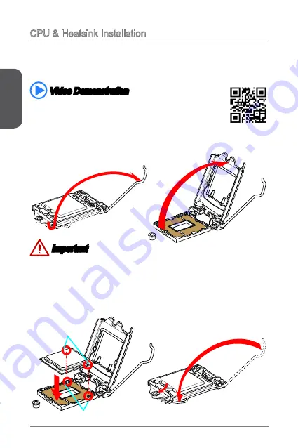
1.  Push the load lever down to unclip it and lift to the fully open position.
2.  The load plate will automatically lift up as the load lever is pushed to the fully 

open position.

 Important

Do not touch the socket contacts or the bottom of the CPU.

 Video Demonstration

Watch the video to learn how to install CPU & heatsink. at the 

address below.
http://youtu.be/bf5La099urI 

Alignment Key

CPU notches

3.  Align the notches with the socket alignment keys. Lower the CPU straight down, 

without tilting or sliding the CPU in the socket. Inspect the CPU to check if it is 

properly seated in the socket.

4.  Close and slide the load plate under the retention knob. Close and engage the 

load lever. 

Summary of Contents for B85M-E33 Series

Page 1: ...COM1 SATA4 SATA3 SATA1 SATA2 JPWR1 JFP1 JFP2 English Thank you for choosing the H81M P33 H81M E33 H87M P33 H87M E33 B85M P33 B85M E33 Series MS 7817 v1 X Micro ATX motherboard The H81M P33 H81M E33 H8...

Page 2: ...ort supporting a maximum resolution of 1920x1200 60Hz 24bpp Storage Intel H81 H87 B85 Express Chipset 4x SATA ports optional Supports RAID 0 RAID1 RAID 5 and RAID 10 optional Supports Intel Smart Resp...

Page 3: ...orts 1x 4 pin CPU fan connector 1x 4 pin system fan connector 1x 3 pin system fan connector 1x Front panel audio connector 2x System panel connectors 1x Chassis Intrusion connector 1x Clear CMOS jumpe...

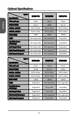
Page 4: ...d Supported Intel Smart Response Not supported Not supported Supported Intel Smart Connect Not supported Not supported Supported Name Speci cation H87M E33 B85M P33 B85M E33 PCIe x16 slot Gen3 Gen3 Ge...

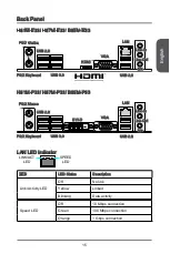
Page 5: ...ed Blinking Data activity Speed LED O 10 Mbps connection Green 100 Mbps connection Orange 1 Gbps connection H81M E33 H87M E33 B85M E33 H81M P33 H87M P33 B85M P33 PS 2 Mouse PS 2 Keyboard USB 2 0 USB 3...

Page 6: ...The load plate will automatically lift up as the load lever is pushed to the fully open position Important Do not touch the socket contacts or the bottom of the CPU Video Demonstration Watch the vide...

Page 7: ...removed from the socket 6 Evenly spread a thin layer of thermal paste or thermal tape on the top of the CPU This will help in heat dissipation and prevent CPU overheating 7 Locate the CPU fan connect...

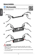
Page 8: ...ress below http youtu be 76yLtJaKlCQ 1 2 3 Important DDR3 memory modules are not interchangeable with DDR2 and the DDR3 standard is not backward compatible Always install DDR3 memory modules in DDR3 D...

Page 9: ...3 3 V 1 5 G r o u n d 3 G r o u n d 1 6 P S O N 4 5 V 1 7 G r o u n d 5 G r o u n d 1 8 G r o u n d 6 5 V 1 9 G r o u n d 7 G r o u n d 2 2 5 V 1 0 1 2 V 2 0 R e s 8 P W R O K 2 3 5 V 1 1 1 2 V 2 1 5...

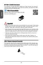
Page 10: ...ch as HDDs SSDs and optical drives be screwed down into the case Refer to the manual that came with your computer case or your SATA device for further installation instructions Please do not fold the...

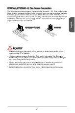
Page 11: ...le system fan connector 1 G r o u n d 2 1 2 V 3 S e n s e 4 S p e e d C o n t r o l 1 G r o u n d 2 1 2 V 3 N o U s e CPUFAN SYSFAN1 SYSFAN2 Important Please refer to your processor s o cial website o...

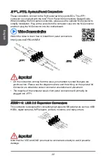
Page 12: ...w i t c h H D D L E D P o w e r S w i t c h P o w e r L E D 7 9 R e s e r v e d 8 6 4 2 JFP1 JFP2 Important On the connectors coming from the case pins marked by small triangles are positive wires Pl...

Page 13: ...i n 6 M I C D e t e c t i o n 4 N C 2 G r o u n d JTPM1 TPM Module Connector This connector connects to a TPM Trusted Platform Module Please refer to the TPM security platform manual for more details...

Page 14: ...MOS RAM Keep Data Clear Data 1 1 Important You can clear the CMOS RAM by shorting this jumper while the system is o Afterwards open the jumper Do not clear the CMOS RAM while the system is on because...

Page 15: ...n card PCIe 2 0 x1 Slot PCIe 3 0 x16 Slot Important When adding or removing expansion cards always turn o the power supply and unplug the power supply power cable from the power outlet Read the expans...

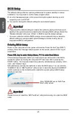
Page 16: ...opriate BIOS con guration Entering BIOS Setup Power on the computer and the system will start the Power On Self Test POST process When the message below appears on the screen please DEL key to enter B...

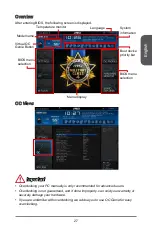
Page 17: ...display BIOS menu selection Language Virtual OC Genie Button Model name OC Menu Important Overclocking your PC manually is only recommended for advanced users Overclocking is not guaranteed and if do...

Page 18: ...hen the installed CPU supports this function Enabled Enables this function to boost CPU performance automatically above rated speci cations when system request the highest performance state Disabled D...

Page 19: ...Memory will completely imitate the archive of rst initiation and rst training After that the memory will not be initialed and trained when booting to accelerate the system booting time Disabled The m...

Page 20: ...it Enabled Intel s Execute Disable Bit functionality can prevent certain classes of malicious bu er over ow attacks where worms attempt to execute code to damage the system It is recommended that keep...

Page 21: ...U power consumption accordingly Disabled Disable this function C1E Support Disabled Enables or disables the C1E function for power saving in halt state This item appears when Intel C State is enabled...

Page 22: ...P power limit for CPU in Turbo Boost mode CPU Current limit A Auto Sets maximum current limit of CPU package in Turbo Boost mode When the current is over the speci ed limit value the CPU will automati...

Reviews: