background image

59

BIOS Setup


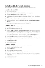
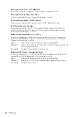
CPU Memory Changed Detect [Enabled]*

Enables or disables the system to issue a warning message during boot when the CPU 

or memory has been replaced.
[Enabled]  

The system will issue a warning message during boot and than needs to 

load the default settings for new devices.

[Disabled]   Disables this function and keeps the current BIOS settings.


OC Quick View Timer [3 Sec]* 

Sets the duration of OC setting values showed on the screen. If set to Disabled,  BIOS 

will not show the variations of OC setting.


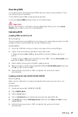
▶ CPU Specifications

Press 

Enter

 to enter the sub-menu. This sub-menu displays the information of 

installed CPU. You can also access this information menu at any time by pressing [F4]. 

Read only.


CPU Technology Support

Press 

Enter 

to enter the sub-menu. The sub-menu shows the key features of 

installed CPU. Read only.


MEMORY-Z

Press 

Enter

 to enter the sub-menu. This sub-menu displays all the settings and 

timings of installed memory. You can also access this information menu at any time by 

pressing [F5]. 


DIMMx Memory SPD

Press 

Enter

 to enter the sub-menu. The sub-menu displays the information of 

installed memory. Read only.


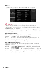
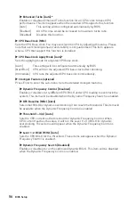
CPU Features

Press 

Enter

 to enter the sub-menu.


Hyper-Threading [Enabled]

Intel Hyper-Threading technology treats the multi cores inside the processor as 

multi logical processors that can execute instructions simultaneously. In this way, 

the system performance is highly improved. This item appears when the installed 

CPU supports this technology.

[Enable] 

Enables Intel Hyper-Threading technology.

[Disabled]   Disables this item if the system does not support HT function.

Summary of Contents for Creator X299

Page 1: ...ur Installation Ihres Computers Manche Installationen bieten auch die Videodemonstrationen Klicken Sie auf die URL um diese Videoanleitung mit Ihrem Browser auf Ihrem Handy oder Table anzusehen Oder s...

Page 2: ...II Quick Start 1 2 3 6 4 5 7 8 9 10 11 12 13 https youtu be ecdkLMmkya4 Installing a Processor Installation des Prozessors Installer un processeur...

Page 3: ...tu be T03aDrJPyQs B1 B2 A1 A2 CPU C2 C1 D2 D1 1 DIMM Intel Core X series 10000 9000 78xx above processors 2 DIMMs 4 DIMMs 8 DIMMs 1 2 2 3 Installing DDR4 memory Installation des DDR4 Speichers Install...

Page 4: ...et Switch Reserved Power Switch JFP1 1 HDD LED 2 Power LED 3 HDD LED 4 Power LED 5 Reset Switch 6 Power Switch 7 Reset Switch 8 Power Switch 9 Reserved 10 No Pin R E S E T S W P O W E R S W P O W E R...

Page 5: ...V Quick Start BAT1 1 2 Installing the Motherboard Installation des Motherboards Installer la carte m re...

Page 6: ...VI Quick Start http youtu be gkDYyR_83I4 ATX_PWR1 CPU_PWR3 PCIE_PWR1 CPU_PWR1 CPU_PWR2 Connecting the Power Connectors Stromanschl sse anschliessen Connecter les c bles du module d alimentation...

Page 7: ...VII Quick Start http youtu be RZsMpqxythc 1 2 3 4 5 Installing SATA Drives Installation der SATA Laufwerke Installer le disque dur SATA SATA...

Page 8: ...VIII Quick Start 1 http youtu be mG0GZpr9w_A 2 3 4 5 6 Installing a Graphics Card Einbau der Grafikkarte Installer une carte graphique...

Page 9: ...IX Quick Start Connecting Peripheral Devices Peripherieger te Connecter un p riph rique anschliessen...

Page 10: ...X Quick Start 4 3 1 2 Power On Einschalten Mettre sous tension...

Page 11: ...ts Key M 22 SATA1 8 SATA 6Gb s Connectors 26 JFP1 JFP2 Front Panel Connectors 26 CPU_PWR1 3 ATX_PWR1 PCIE_PWR1 Power Connectors 27 OC1 OC GENIE 4 Knob 28 OC_RT1 OC Retry Jumper 30 OC_FS1 OC Force Ente...

Page 12: ...SAIR Connector 40 Onboard LEDs 41 EZ Debug LED 41 JPWRLED1 LED power input 41 XMP LED 41 Multi BIOS LEDs 42 Debug Code LED 42 Hexadecimal Character Table 42 Boot Phases 42 Debug Code LED Table 43 Inst...

Page 13: ...e computer before installation is completed This could cause permanent damage to the components as well as injury to the user If you need help during any installation step please consult a certified c...

Page 14: ...x8 and x16 x0 x16 x8 modes with the 48 lane CPU Support x8 x8 x16 x8 and x16 x0 x16 x8 modes with the 44 lane CPU Support x8 x8 x8 x0 and x16 x0 x8 x0 modes with the 28 lane CPU The PCI_E4 slot will r...

Page 15: ...age devices M2_3 slot is unavailable with 28 lane CPU RAID Intel X299 Chipset Supports RAID 0 RAID 1 RAID 5 and RAID 10 for SATA storage devices Supports RAID 0 and RAID 1 for M 2 PCIe storage devices...

Page 16: ...n connectors 2x 4 pin extend system fan connectors 1x 4 pin water pump fan connector 1x 3 pin Water Flow connector 1x Front panel audio connector 2x System panel connectors 1x TPM module connector 1x...

Page 17: ...DIF Out connector I O Controller NUVOTON NCT6797 Controller Chip Hardware Monitor CPU System temperature detection CPU System fan speed detection CPU System fan speed control Form Factor EATX Form Fac...

Page 18: ...m manual mb CREATORCENTER pdf for more details Special Features Audio Audio Boost 4 Nahimic 3 Voice Boost Network 10G Super LAN LAN Manager Dual LAN Intel WiFi Storage Triple Turbo M 2 Cooling Extende...

Page 19: ...elding Performance Multi GPU SLI Technology Multi GPU CrossFire Technology DDR4 Boost Core Boost OC Engine Clock gen USB with type A C Lightning USB Lightning USB 20G Front Lightning USB 20PIN Triple...

Page 20: ...t should contain Motherboard Creator X299 Documentation User manual 1 Quick installation guide 1 Application USB drive with drivers utilities 1 Cables SATA 6Gb s cable 4 LED JRGB Y cable 1 LED JCORSAI...

Page 21: ...l 2 4 6 8 Center Subwoofer Out Rear Speaker Out Line In Side Speaker Out Line Out Front Speaker Out Mic In connected Blank empty Rear I O Panel PS 2 Combo port 1Gbps LAN 10 Gbps LAN USB 2 0 Type A Aud...

Page 22: ...rols the volume or balance the right left side of the speakers that you plugged in front or rear panel by adjust the bar Jack Status depicts all render and capture devices currently connected with you...

Page 23: ...Rear I O Panel Audio jacks to headphone and microphone diagram Audio jacks to stereo speakers diagram Audio jacks to 7 1 channel speakers diagram AUDIO INPUT AUDIO INPUT Rear Front Side Center Subwoof...

Page 24: ...14 Rear I O Panel Installing Antennas 1 Combine the antenna with the base 2 Screw two antenna cables tight to the WiFi antenna connectors as shown 1 2 3 Place the antenna as high as possible...

Page 25: ...2_1 JFP1 SATA 3 4 SATA 1 2 JUSB5 JUSB4 SATA 5 6 SATA 7 8 CPU_FAN1 PUMP_FAN1 PCI_E1 PCI_E2 PCI_E3 M2_3 M2_2 M2_1 SYS_FAN1 PCI_E4 JTPM1 CPU Socket CPU_PWR1 CPU_PWR2 CPU_PWR3 OC1 JCORSAIR1 JRAINBOW1 JUSB...

Page 26: ...ability Confirm that the CPU heatsink has formed a tight seal with the CPU before booting your system Overheating can seriously damage the CPU and motherboard Always make sure the cooling fans work pr...

Page 27: ...on recommendation B1 B2 A1 A2 CPU C2 C1 D2 D1 1 DIMM Intel Core X series 10000 9000 78xx above processors 2 DIMMs 3 DIMMs 4 DIMMs 5 DIMMs 6 DIMMs 7 DIMMs 8 DIMMs BAT1 DIMMD1 DIMMA2 DIMMD2 DIMMA1 DIMMC...

Page 28: ...PD Go to BIOS and find the DRAM Frequency to set the memory frequency if you want to operate the memory at the marked or at a higher frequency It is recommended to use a more efficient memory cooling...

Page 29: ...x8 3 0 x8 M2_2 3 0 x4 3 0 x4 3 0 x4 3 0 x4 3 0 x4 3 0 x4 M2_3 3 0 x4 3 0 x4 3 0 x4 3 0 x4 3 0 x4 3 0 x4 graphics card slot best combination for 44 lane CPU Graphics Card 2 Way 2 Way 2 Way 3 Way 3 Way...

Page 30: ...on of the slot For a single PCIe x16 expansion card installation with optimum performance using the PCI_E1 slot is recommended When adding or removing expansion cards always turn off the power supply...

Page 31: ...is connector is a U 2 interface port Each connector can connect to one PCIe 3 0 x4 NVMe storage device Installing U 2 SSD 1 Connect the U 2 cable to the U 2 connector on the motherboard 2 Connect the...

Page 32: ...2 SHIELD FROZR heatsink 2 Lift the M 2 SHIELD FROZR heatsink and remove the protective films from the thermal pads 2 1 1 1 1 1 1 1 Important Intel RST only supports PCIe M 2 SSD with UEFI ROM Intel O...

Page 33: ...remove the M 2 standoff 4 Insert your M 2 SSDs into the M 2 slots at a 30 degree angle 5 If the M 2 SSD is shorter than the M 2 SHIELD FROZR heatsink please secure the M 2 SSD in place with M 2 screw...

Page 34: ...2 standoff 3 Loosen M 2 standoff 4 Move and fasten M 2 standoff to the appropriate location for your M 2 SSD 5 Insert your M 2 SSD into the M 2 slot at a 30 degree angle 6 Secure the M 2 device in pla...

Page 35: ...ard into the PCI_E1 or PCI_E3 slot 10 Use the screw to secure the M 2 XPANDER AERO card 11 Connect the PCIE_PWR1 to the power supply 12 Connect the case s HDD LED cable to the JCASE connector 13 Using...

Page 36: ...cables have identical plugs on either sides of the cable However it is recommended that the flat connector be connected to the motherboard for space saving purposes JFP1 JFP2 Front Panel Connectors Th...

Page 37: ...V 11 12V 23 5V 12 3 3V 24 Ground 5 4 1 8 CPU_PWR1 3 1 Ground 5 12V 2 Ground 6 12V 3 Ground 7 12V 4 Ground 8 12V Important Make sure that all the power cables are securely connected to a proper ATX pow...

Page 38: ...radiator for better cooling and performance You can also control the OC GENIE 4 function in BIOS Setup or with MSI CREATOR CENTER software In order to optimize performance and improve system stability...

Page 39: ...Hz 3 5 GHz 3 3 GHz 1 4 3 GHz 4 5 GHz 4 2 GHz 4 5 GHz 4 5 GHz 4 5 GHz 2 4 4 GHz 4 6 GHz 4 3 GHz 4 6 GHz 4 6 GHz 4 6 GHz 4 4 5 GHz 4 7 GHz 4 4 GHz 4 7 GHz 4 7 GHz 4 7 GHz 6 4 6 GHz 4 8 GHz 4 5 GHz 4 8 G...

Page 40: ...nd skip OC failure messages JSLOW1 Slow Mode Booting Jumper This jumper is used for LN2 cooling solution that provides the extreme overclocking conditions to boot at a stable processor frequency and t...

Page 41: ...ion 1 Ground 2 Voltage Control 3 Sense 4 NC Pin definition of fan connectors 1 CPU_FAN1 SYS_FAN1 SYS_FAN4 Default Auto mode SYS_FAN2 SYS_FAN3 EXS_FAN1 EXS_FAN2 Default Auto mode 1 CPU_FAN1 PUMP_FAN1 S...

Page 42: ...ect the theral sensor cable and use it to monitor the temperature of the detection point Thermistor cable GND Sense V Check Points Lite These voltage checkpoints are used to measure the current system...

Page 43: ...USB Type C port on the front panel JUSB3 4 USB 3 2 Gen1 Connector These connectors allow you to connect USB 3 2 Gen1 ports on the front panel Important Note that the Power and Ground pins must be conn...

Page 44: ...amage In order to recharge your iPad iPhone and iPod through USB ports please install MSI CREATOR CENTER utility 1 2 14 13 1 LPC Clock 2 3V Standby power 3 LPC Reset 4 3 3V Power 5 LPC address data pi...

Page 45: ...intrusion detector 1 Connect the JCI1 connector to the chassis intrusion switch sensor on the chassis 2 Close the chassis cover 3 Go to BIOS SETTINGS Security Chassis Intrusion Configuration 4 Set Cha...

Page 46: ...ting BIOS to default values 1 Power off the computer and unplug the power cord 2 Use a jumper cap to short JBAT1 for about 5 10 seconds 3 Remove the jumper cap from JBAT1 4 Plug the power cord and Pow...

Page 47: ...er 2 Switch to the normal BIOS ROM with Multi BIOS switch 3 Insert the USB flash drive into the computer 4 Power on the computer and press Del key to enter BIOS setup during POST 5 Select the M FLASH...

Page 48: ...ord from the power outlet before installing or removing the RGB LED strip Please use MSI s software to control the extended LED strip JRGB1 RGB LED connector The JRGB connector allows you to connect t...

Page 49: ...connector supports up to 200 LEDs Always turn off the power supply and unplug the power cord from the power outlet before installing or removing the RGB LED strip Please use MSI s software to control...

Page 50: ...Important Fans must start at 1 and continue in series 1 2 3 4 5 6 Any fan not connected in series will break communication and the RGB LED lighting function will not work Quantity of RGB LED Fans or R...

Page 51: ...RAM is not detected or fail VGA indicates GPU is not detected or fail BOOT indicates the booting device is not detected or fail Onboard LEDs JPWRLED1 LED power input This connector is used by retailer...

Page 52: ...Red BIOS A White BIOS B Hexadecimal Character Table Hexadecimal 0 1 2 3 4 5 6 7 8 9 A B C D E F Debug Code LED display 0 1 2 3 4 5 6 7 8 9 A B C D E F Boot Phases Security SEC initial low level initi...

Page 53: ...stem Agent module specific 19 Pre memory PCH initialization is started 1A 1C Pre memory PCH initialization PCH module specific 2B Memory initialization Serial Presence Detect SPD data reading 2C Memor...

Page 54: ...s 63 CPU DXE initialization is started 64 67 CPU DXE initialization CPU module specific 68 PCI host bridge initialization 69 System Agent DXE initialization is started 6A System Agent DXE SMM initiali...

Page 55: ...ystem Reset B4 USB hot plug B5 PCI bus hot plug B6 Clean up of NVRAM B7 Configuration Reset reset of NVRAM settings B8 BF Reserved for future AMI codes DXE Error Codes D0 CPU initialization error D1 S...

Page 56: ...Recovery PPI is not available F9 Recovery capsule is not found FA Invalid recovery capsule FB FF Reserved for future AMI error codes ACPI States Codes The following codes appear after booting and the...

Page 57: ...notification then select Run DVDSetup exe to open the installer If you turn off the AutoPlay feature from the Windows Control Panel you can still manually execute the DVDSetup exe from the root path...

Page 58: ...the product you purchased Entering BIOS Setup Please refer the following methods to enter BIOS setup Press Delete key when the Press DEL key to enter Setup Menu F11 to enter Boot Menu message appears...

Page 59: ...boot and press Ctrl F5 key during POST and click on Yes to reboot the system Reboot and press Del key during POST to enter BIOS Click the M FLASH button and click on Yes to reboot the system 3 Select...

Page 60: ..._PWR1 and ATX_PWR1 No need to install CPU and memory 4 Plug the USB flash drive that contains the MSI ROM file into the Flash BIOS Port on the rear I O panel 5 Press the Flash BIOS Button to flash BIO...

Page 61: ...alled processor supports this function Important Please don t make any changes in OC menu and don t load defaults to keep the optimal performance and system stability after activating the OC GENIE 4 f...

Page 62: ...splay the M Flash menu that provides the way to update BIOS with a USB flash drive Hardware Monitor click on this button to display the Hardware Monitor menu that allows you to manually control the fa...

Page 63: ...e available SETTINGS allows you to specify the parameters for chipset and boot devices OC allows you to adjust the frequency and voltage Increasing the frequency may get better performance M FLASH pro...

Page 64: ...ngs Normal Provides the regular OC settings in BIOS setup Expert Provides the advanced OC settings for OC expert to configure in BIOS setup Note We use as the symbol for the OC settings of Expert mode...

Page 65: ...n set If set to Auto BIOS will configure this setting automatically This item appears when the installed CPU supports this function Ring Ratio Auto Sets the ring ratio The valid value range depends on...

Page 66: ...e clock immediately Clockgen Features optional Press Enter to enter the sub menu Sets the detailed clockgen features Dynamic Frequency Control Disabled Enables or disables to try different CPU BCLK un...

Page 67: ...Auto Sets the value for SATA clock Amplitude BCLK Slew Rate Auto Sets the value for BCLK Slew Rate for overclocking The value might vary depending on the actual overclocking scenario BCLK ORT Duratio...

Page 68: ...ar the CMOS data and enter the BIOS to load the default settings Memory Fast Boot Auto Enables or disables the initiation and training for memory every booting Auto The setting will be configured auto...

Page 69: ...ly CPU Technology Support Press Enter to enter the sub menu The sub menu shows the key features of installed CPU Read only MEMORY Z Press Enter to enter the sub menu This sub menu displays all the set...

Page 70: ...logy and allows a platform to run multiple operating systems in independent partitions The system can function as multiple systems virtually Disabled Disables this function Intel VT D Tech Disabled En...

Page 71: ...s setting will be configured automatically by BIOS Enabled Detects the idle state of system and reduce CPU power consumption accordingly Disabled Disable this function C1E Support Disabled Enables or...

Page 72: ...tion Auto Enables or disables the over voltage protection and over current protection for CPU internal VR Voltage Regulator This item only appears when a CPU that support this function is installed Au...

Page 73: ...22 SATA1 8 SATA 6Gb s Anschl sse 26 JFP1 JFP2 Frontpanel Anschl sse 26 CPU_PWR1 3 ATX_PWR1 PCIE_PWR1 Stromanschl sse 27 OC1 OC GENIE 4 Drehschalter 28 OC_RT1 OC Retry Steckbr cke 30 OC_FS1 Steckbr cke...

Page 74: ...EZ Debug LED 41 JPWRLED1 LED Stromzufuhr 41 XMP LED 41 Multi BIOS LEDs 42 Debug Code LED 42 Hexadezimalzeichen 42 Boot Phasen 42 Debug Code LED Tabelle 43 ACPI Status Codes 46 CPU Temperatur 46 Instal...

Page 75: ...uter nicht bevor die Installation abgeschlossen ist Dies k nnte permanente Sch den an den Komponenten sowie zu das Verletzung des Benutzers verursachen Sollten Sie Hilfe bei der Installation ben tigen...

Page 76: ...x8 x8 x16 x8 und x16 x0 x16 x8 mit der 44 Lane CPU Unterst tzen den Modi x8 x8 x8 x0 und x16 x0 x8 x0 mit der 28 Lane CPU Der PCI_E4 Steckplatz erlaubt eine bertragungsgeschwindigkeit 3 0 x4 mit der...

Page 77: ...0 RAID 1 RAID 5 und RAID 10 f r SATA Speicherger te Unterst tzt RAID 0 und RAID 1 f r M 2 PCIe Speicherger te USB ASMedia ASM3242 Chipsatz 1x USB 3 2 Gen2x2 SuperSpeed USB 20 Gbps Typ C Anschluss an d...

Page 78: ...r Anschl sse 2x 4 polige erweiterten System L fter Anschl sse 1x 4 poliger Anschluss f r die Wasserpumpe 1x 3 poliger Anschluss des Wasserdurchflusssensors 1x Audioanschluss des Frontpanels 2x System...

Page 79: ...iobuchsen 1x Optischer S PDIF Ausgang E A Anschluss NUVOTON NCT6797 Controller Chip Hardware Monitor CPU System Temperaturerfassung CPU System Geschwindigkeitserfassung CPU System L fterdrehzahlregelu...

Page 80: ...msi com manual mb CREATORCENTER pdf Besondere Funktionen Audio Audio Boost 4 Nahimic 3 Voice Boost Netzwerk 10G Super LAN LAN Manager Dual LAN Intel WiFi Speicherung Triple Turbo M 2 K hlung Erweiter...

Page 81: ...e Leistung Multi GPU SLI Technologie Multi GPU CrossFire Technologie DDR4 Boost Core Boost OC Engine Clock gen USB Anschluss mit Typ A C Lightning USB Lightning USB 20G Front Lightning USB 20PIN Dreif...

Page 82: ...te enthalten Motherboard Creator X299 Dokumentation Benutzerhandbuch 1 Schnellinstallationsanleitung 1 Anwendung USB Laufwerk mit Treibern Dienstprogramme 1 Kabel SATA 6Gb s Kabel 4 LED JRGB Y Kabel 1...

Page 83: ...oofer Ausgang Hinterer Lautsprecher Line In Seitliche Lautsprecher Line Out Vorderer Lautsprecher Mic In Verbindet Blank Leer R ckseite E A PS 2 Combo Anschluss 1Gbit s LAN 10 Gbit s LAN USB 2 0 Typ A...

Page 84: ...rke und die Balance Einstellung der Lautsprecher die im Front Panel oder auf der R ckseite des PCs eingesteckt sind Verbindungsstatus Bildet die angeschlossenen Render und Capture Ger te ab Anschl sse...

Page 85: ...ckseite E A Audiobuchsen f r den Anschluss von einem Kopfh rer und Mikrofon Audiobuchsen f r Stereo Lautsprecher Audiobuchsen f r 7 1 Kanal Anlage AUDIO INPUT AUDIO INPUT Rear Front Side Center Subwo...

Page 86: ...eite E A Antennen installieren 1 Verbinden Sie Antenne mit dem Antennenfu 2 Schrauben Sie wie gezeigt die Antennen fest an die Wi Fi Antennenanschl sse 1 2 3 Positionieren Sie die Antennen so hoch wie...

Page 87: ...U2_1 JFP1 SATA 3 4 SATA 1 2 JUSB5 JUSB4 SATA 5 6 SATA 7 8 CPU_FAN1 PUMP_FAN1 PCI_E1 PCI_E2 PCI_E3 M2_3 M2_2 M2_1 SYS_FAN1 PCI_E4 JTPM1 CPU Sockel CPU_PWR1 CPU_PWR2 CPU_PWR3 OC1 JCORSAIR1 JRAINBOW1 JU...

Page 88: ...te Verbindung mit der CPU hergestellt hat bevor Sie Ihr System starten berhitzung besch digt die CPU und das System nachhaltig Stellen Sie stets eine korrekte Funktionsweise des CPU K hlers sicher um...

Page 89: ...onsempfehlung B1 B2 A1 A2 CPU C2 C1 D2 D1 1 DIMM Intel Core X Serie 10000 9000 78xx vorgenannte Serie Prozessoren 2 DIMMs 3 DIMMs 4 DIMMs 5 DIMMs 6 DIMMs 7 DIMMs 8 DIMMs BAT1 DIMMD1 DIMMA2 DIMMD2 DIMM...

Page 90: ...llen Sie im BIOS Setup mit DRAM Frequency die Speicherfrequenz ein wenn Sie mit der festgelegten oder einer h heren Speicherfrequenz arbeiten m chten Es wird empfohlen ein effizienteres Speicherk hlsy...

Page 91: ...3 0 x4 3 0 x4 3 0 x4 3 0 x4 3 0 x4 M2_3 3 0 x4 3 0 x4 3 0 x4 3 0 x4 3 0 x4 3 0 x4 Steckplatz f r Grafikkarte Beste Kombination F r eine 44 Lane CPU Graphik karte 2 Wege 2 Wege 2 Wege 3 Wege 3 Wege 4 W...

Page 92: ...tallation einer einzelnen PCIe x16 Erweiterungskarte mit optimaler Leistung empfehlen wir den PCI_E1 Steckplatz zu verwenden Achten Sie darauf dass Sie den Strom abschalten und das Netzkabel aus der S...

Page 93: ...t ein U 2 Schnittstellenmodul Pro Anschluss kann ein PCIe 3 0 x4 NVMe Speicherger t angeschlossen werden Installation einer U 2 SSD 1 Schlie en Sie das U 2 Kabel an die U 2 Steckverbindung des Motherb...

Page 94: ...SHIELD FROZR 2 Heben Sie den M 2 SHIELD FROZR an und entfernen Sie die Schutzfolie von den W rmeleitpads 2 1 1 1 1 1 1 1 Wichtig Intel RST unterst tzt nur PCIe M 2 SSD mit UEFI ROM Intel Optane Techn...

Page 95: ...lter 4 Stecken Sie eine M 2 SSD im 30 Grad Winkel in den M 2 Steckplatz 5 Wenn die L nge der M 2 SSD kleiner als die L nge des M 2 SHIELD FROZR K hlk rpers ist schrauben Sie den M 2 SSD mit 8 5H M 2 S...

Page 96: ...andshalter 4 Entfernen Sie den M 2 Abstandshalter und befestigen Sie ihn an der entsprechenden Position Ihrer M 2 SSD 5 Stecken Sie eine M 2 SSD im 30 Grad Winkel in den M 2 Steckplatz 6 Schrauben Sie...

Page 97: ...eckplatz 10 Befestigen Sie die M 2 XPANDER AERO Karte mit Schraube am Geh use 11 Verbinden Sie PCIE_PWR1 an die Stromversorgung 12 Verbinden Sie das HDD LED Kabel des Geh uses mit dem JCASE Anschluss...

Page 98: ...tenverlust k nnte die Folge sein SATA Kabel haben identische Stecker an beiden Enden Es wird empfohlen den flachen Stecker auf dem Motherboard einstecken JFP1 JFP2 Frontpanel Anschl sse Diese Anschl s...

Page 99: ...3 5V 12 3 3V 24 Ground 5 4 1 8 CPU_PWR1 3 1 Ground 5 12V 2 Ground 6 12V 3 Ground 7 12V 4 Ground 8 12V Wichtig Stellen Sie sicher dass alle Anschl sse mit den richtigen Anschl ssen des Netzteils verbun...

Page 100: ...Dual Fan Radiator einzusetzen um eine bessere K hlung und h here Leistung zu gew hrleisten Sie k nnen auch die OC GENIE 4 Funktion im BIOS Setup oder mit der MSI CREATOR CENTER Software steuern Nach...

Page 101: ...z 3 5 GHz 3 5 GHz 3 3 GHz 1 4 3 GHz 4 5 GHz 4 2 GHz 4 5 GHz 4 5 GHz 4 5 GHz 2 4 4 GHz 4 6 GHz 4 3 GHz 4 6 GHz 4 6 GHz 4 6 GHz 4 4 5 GHz 4 7 GHz 4 4 GHz 4 7 GHz 4 7 GHz 4 7 GHz 6 4 6 GHz 4 8 GHz 4 5 GH...

Page 102: ...System in den BIOS gezwungen ohne die OC_Fail Meldung anzuzeigen JSLOW1 Slow Mode Booting Steckbr cke Die Steckbr cke wird f r die LN2 K hlungen verwendet Der Slow Mode startet den Prozessor in einer...

Page 103: ...ontrol 3 Sense 4 NC Pin Belegung der L fteranschl sse 1 CPU_FAN1 SYS_FAN1 SYS_FAN4 Standardwert Modus zur automatischen Erkennung SYS_FAN2 SYS_FAN3 EXS_FAN1 EXS_FAN2 Standardwert Modus zur automatisch...

Page 104: ...Temperaturf hler Kabel zur berwachung der Temperatur eines gew hlten Erfassungsbereichs anschlie en Temperaturf hler Kabel GND Sense Spannungsmesspunkte Die Spannungsmesspunkte werden verwendet um die...

Page 105: ...Frontpanel JUSB3 4 USB 3 2 Gen1 Anschl sse Mit diesen Anschl ssen k nnen Sie die USB 3 2 Gen1 Anschl sse auf dem Frontpanel verbinden Wichtig Bitte beachten Sie dass Sie die mit Stromf hrende Leitung...

Page 106: ...zu Sch den kommen Um ein iPad iPhone und einen iPod ber USB Anschl sse aufzuladen installieren Sie bitte die MSI CREATOR CENTER Software 1 2 14 13 1 LPC Clock 2 3V Standby power 3 LPC Reset 4 3 3V Pow...

Page 107: ...s am Geh usekontakt Schalter Sensor am Geh use an 2 Schlie en Sie die Geh useabdeckung 3 Gehen Sie zu BIOS SETTINGS Security Chassis Intrusion Configuration 4 Stellen Sie Chassis Intrusion auf Enabled...

Page 108: ...Sie den Computer ab und ziehen Sie das Netzkabel ab 2 Verwenden Sie eine Steckbr cke um JBAT1 f r 5 10 Sekunden kurzzuschlie en 3 Entfernen Sie die Steckbr cke von JBAT1 4 Stecken Sie das Kabel Ihres...

Page 109: ...BIOS ROM mit dem Multi BIOS Schalter 3 Schlie en das USB Flashlaufwerk an den Computer an 4 Schalten Sie den Computer ein und dr cken Sie w hrend des POST Vorgangs die Taste Del Entf um das BIOS zu ff...

Page 110: ...ie RGB LED Streifen ein und ausbauen Bitte verwenden Sie die MSI Software zur Steuerung des LED Leuchtstreifens JRGB1 RGB LED Anschluss Mit dem JRGB Anschluss k nnen Sie den 5050 RGB LED Streifen 12 V...

Page 111: ...unterst tzt dieser Anschluss bis zu 200 LEDs Schalten Sie die Stromversorgung aus und ziehen Sie das Netzkabel ab bevor Sie die RGB LED Streifen ein und ausbauen Bitte verwenden Sie die MSI Software z...

Page 112: ...Reihenfolge 1 2 3 4 5 6 Falls Sie den L fter in einer falschen Reihenfolge verbinden wird die Kommunikation gest rt und die RGB LEDs funktionieren nicht Die Anzahl der RGB LED L fter oder der RGB LED...

Page 113: ...der ist fehlerhaft VGA GPU wird nicht erkannt oder ist fehlerhaft BOOT Boot Ger t wird nicht erkannt oder ist fehlerhaft Onboard LEDs JPWRLED1 LED Stromzufuhr Dieser Anshcluss erm glicht es dem Fachh...

Page 114: ...Betrieb ist Rot BIOS A Wei BIOS B Hexadezimalzeichen Hexadezimal 0 1 2 3 4 5 6 7 8 9 A B C D E F Debug Code LED Anzeige 0 1 2 3 4 5 6 7 8 9 A B C D E F Boot Phasen Sicherheit SEC Low Level Initialisie...

Page 115: ...nt Initialisierung System Agent spezifisch 19 Pre Memory PCH Initialisierung wird gestartet 1A 1C Pre Memory PCH Initialisierung PCH Modul spezifisch 2B Speicher Initialisierung Serial Presence Detect...

Page 116: ...60 DXE Core wird gestartet 61 NVRAM Initialisierung 62 Installation des PCH Runtime Services 63 CPU DXE Initialisierung wird gestartet 64 67 CPU DXE Initialisierung CPU modulspezifisch 68 PCI Host Bri...

Page 117: ...etzung B4 USB Hot Plug B5 PCI Bus Hot Plug B6 NVRAM aufr umen B7 Setzt die Konfiguration zur ck setzt die NVRAM Einstellungen zur ck B8 BF Reserviert f r zuk nftige AMI Codes DXE Fehler Codes D0 CPU I...

Page 118: ...F7 Reserviert f r zuk nftige AMI Fortschrittscodes Wiederherstellung Fehler Codes F8 Wiederherstellung PPI ist nicht verf gbar F9 Wiederherstellung Kapsel ist nicht gefunden FA Ung ltige Wiederherste...

Page 119: ...entr ger aus und w hlen Sie DVDSetup exe starten aus um den Installer zu ffnen Wenn Sie die AutoPlay Funktionen in der Windows Systemsteuerung ausschalten k nnen Sie das Programm DVDSetup exe im Haupt...

Page 120: ...des BIOS Setups Befolgen Sie bitte die nachfolgende Schritte um das BIOS Setup aufzurufen W hrend des BOOT Vorgangs dr cken Sie die Taste ENTF wenn die Meldung Press DEL key to enter Setup Menu F11 t...

Page 121: ...en Beim Neustart dr cken Sie w hrend des POST Vorgangs die Taste Ctrl F5 und klicken Sie auf Yes Ja tum das System neu zu starten Beim Neustart dr cken Sie w hrend des POST Vorgangs die Taste Del Entf...

Page 122: ...s FAT32 format 3 Verbinden Sie die Stromversorgung an dem CPU_PWR1 und ATX_PWR1 Stecker Sie ben tigen keine CPU und keinen Speicher zu installieren 4 Stecken Sie das USB Flashlaufwerk das die MSI ROM...

Page 123: ...n Sie keine Werte im OC Men und laden Sie keine Standardwerte w hrend OC GENIE 4 aktiviert ist um die optimale Leistung und Stabilit t des Systems zu gew hrleisten XMP Schalter Klicken Sie auf den inn...

Page 124: ...rdware Monitor Ein Klick auf diese Schaltfl che ffnet das Men des Hardware Monitor mit dem Sie die L fterdrehzahl in Prozent manuell steuern Favoriten Dr cken Sie die F3 Taste um das Favoriten Men auf...

Page 125: ...nnen Sie die Parameter f r Chipsatz Boot Ger te angeben OC Hier k nnen Sie die Frequenz und Spannung anpassen Die Erh hung der Frequenz kann eine bessere Leistung erreichen M FLASH M Flash erlaubt es...

Page 126: ...rsion des OC Einstellungen anzuzeigen Normal Bietet normale bertaktungseinstellungen im BIOS Setup Expert Bietet die erweiterten bertaktungseinstellungen f r den erfahrenen Benutzer welche die Einstel...

Page 127: ...tellung auf Auto gesetzt ist wird das BIOS diese Einstellungen automatisch konfigurieren Diese Option wird angezeigt wenn die CPU diese Funktion unterst tzt Ring Ratio Auto Setzen Sie den Ring Ratio D...

Page 128: ...dtakt sofort Clockgen Features optional Dr cken Sie die Eingabetaste Enter um das Untermen aufzurufen Steuert die Einstellungen des CPU Takts Dynamic Frequency Control Disabled Aktiviert oder deaktivi...

Page 129: ...Auto Setzt den Wert des SATA Takt Amplitudes BCLK Slew Rate Auto Setzt den Wert des BCLK Slew Rate f r bertaktung Der Wert kann abh ngig von den aktuellen bertaktung Szenario variieren BCLK ORT Durati...

Page 130: ...n Sie bitte den Abschnitt Steckbr cke zur CMOS L schung Clear CMOS Taste um die CMOS Daten zu l schen und die Standardeinstellungen auf das BIOS zu laden Memory Fast Boot Auto Aktivieren oder deaktivi...

Page 131: ...die wichtigsten Eigenschaften der installierten CPU an MEMORY Z Dr cken Sie die Eingabetaste Enter um das Untermen aufzurufen Dieses Untermen zeigt alle Einstellungen und Timings des installierten Sp...

Page 132: ...einsetzen Disabled Deaktiviert diese Funktion Intel VT D Tech Disabled Aktiviert oder deaktiviert die Intel VT D Intel Virtualization for Directed I O Technologie Hardware Prefetcher Enabled Aktiviere...

Page 133: ...s im Leerlauf Diese Option wird angezeigt wenn Intel C State aktiviert ist Enabled Erm glicht die C1E Funktion um die CPU Frequenz und Spannung zur Stromersparnis im Leerlauf zu reduzieren Disabled De...

Page 134: ...Spannungsregulator VR Voltage Regulator Auto Diese Einstellungen werden vom BIOS automatisch konfiguriert Enabled Legt die Spannungsbegrenzung der CPU internen VR f r berspannungsschutz und berstroms...

Page 135: ...TA1 8 Connecteurs SATA 6Gb s 26 JFP1 JFP2 Connecteurs de panneau avant 26 CPU_PWR1 3 ATX_PWR1 PCIE_PWR1 Connecteurs d alimentation 27 OC1 Molette OC GENIE 4 28 OC_RT1 Cavalier OC Retry retenter l OC 3...

Page 136: ...41 JPWRLED1 Indicateur LED de l entr e d alimentation 41 Indicateur LED du mode XMP 41 Indicateurs LED de Multi BIOS 42 Debug Code LED 42 Tableau des caract res hexad cimaux 42 Phase de d marrage 42...

Page 137: ...nt bien fix s sur la carte m re ou ailleurs dans le bo tier de l ordinateur Ne d marrez pas l ordinateur avant d avoir termin l installation Ceci peut endommager les composants ou vous blesser Si vous...

Page 138: ...avec un processeur 48 lignes Support les modes x 8 x 8 x 16 x 8 et x 16 x 0 x 16 x 8 avec un processeur 44 lignes Support les modes x 8 x 8 x 8 x 0 et x 16 x 0 x 8 x 0 avec un processeur 28 lignes Le...

Page 139: ...disponible avec un processeur 28 lignes RAID Chipset Intel X299 Support RAID 0 RAID 1 RAID 5 et RAID 10 pour des p riph riques de stockage SATA Support RAID 0 et RAID 1 pour des p riph riques de stock...

Page 140: ...s pour ventilateur syst me d extension 4 broches 1 x connecteur de ventilateur 4 broches pour la pompe eau 1 x connecteur 3 broches pour syst me de watercooling 1 x connecteur audio avant 2 x connecte...

Page 141: ...cteur Sortie S PDIF optique Contr leur E S Contr leur NUVOTON NCT6797 Moniteur syst me D tection de la temp rature du CPU et du syst me D tection de la vitesse du ventilateur du CPU et du syst me Cont...

Page 142: ...anual mb CREATORCENTER pdf pour plus de d tails Fonctions sp ciales Audio Audio Boost 4 Nahimic 3 Voice Boost Network 10G Super LAN LAN Manager Dual LAN Intel WiFi Stockage Triple Turbo M 2 Cooling Ex...

Page 143: ...talled IO shielding Performance Tecnologie Multi GPU SLI Multi GPU CrossFire DDR4 Boost Core Boost OC Engine Clock gen USB de type A C Lightning USB Lightning USB 20G Front Lightning USB 20PIN Triple...

Page 144: ...e doit contenir Carte m re Creator X299 Documentation Manuel d utilisation 1 Guide d installation rapide 1 Application Cl USB avec pilotes et utilitaires 1 C ble C ble SATA 6Gb s 4 C ble s parateur LE...

Page 145: ...e Sortie Port combo PS 2 1Gbps LAN 10 Gbps LAN USB 2 0 Type A Ports Audio Sortie S PDIF optique Bouton Clear CMOS Connecteur d antenne Wi Fi USB 3 2 Gen 1 Type A Bouton Flash BIOS Bouton Clear CMOS E...

Page 146: ...son gauche droite des haut parleurs branch s sur le panneau avant ou derri re en ajustant la barre de volume Etat des prises Jack pr sente tous les p riph riques de diffusion et de capture connect s...

Page 147: ...sation des ports audio d di s au casque et au microphone Illustration de l utilisation du port audio d di aux haut parleurs Illustration de l utilisation des ports audio d di s aux haut parleurs 7 1 A...

Page 148: ...i re Entr e Sortie Installation des antennes 1 Combiner l antenne avec la base 2 Vissez fermement les antennes aux connecteurs d antenne Wi Fi comme indiqu ci dessous 1 2 3 Placez les antennes le plus...

Page 149: ...2 U2_1 JFP1 SATA 3 4 SATA 1 2 JUSB5 JUSB4 SATA 5 6 SATA 7 8 CPU_FAN1 PUMP_FAN1 PCI_E1 PCI_E2 PCI_E3 M2_3 M2_2 M2_1 SYS_FAN1 PCI_E4 JTPM1 Socket processeur CPU_PWR1 CPU_PWR2 CPU_PWR3 OC1 JCORSAIR1 JRAI...

Page 150: ...ilit du syst me Assurez vous de l tanch it entre le ventilateur et le processeur avant de d marrer votre syst me La surchauffe peut facilement endommager le processeur et la carte m re Assurez vous to...

Page 151: ...e module m moire B1 B2 A1 A2 CPU C2 C1 D2 D1 1 DIMM Processeurs Intel Core 10000 9000 78xx et au dessus de s rie X 2 DIMMs 3 DIMMs 4 DIMMs 5 DIMMs 6 DIMMs 7 DIMMs 8 DIMMs BAT1 DIMMD1 DIMMA2 DIMMD2 DIM...

Page 152: ...et choisissez la fonction DRAM Frequency pour r gler la fr quence de m moire si vous voulez faire fonctionner la m moire la fr quence indiqu e ou une fr quence plus lev e Il est recommand d utiliser...

Page 153: ...2 3 0 x 4 3 0 x 4 3 0 x 4 3 0 x 4 3 0 x 4 3 0 x 4 M2_3 3 0 x 4 3 0 x 4 3 0 x 4 3 0 x 4 3 0 x 4 3 0 x 4 slot de carte graphique meilleure combinaison Pour les processeurs 44 lignes Carte graphique 2 Wa...

Page 154: ...our viter la d formation du slot Si vous choisissez d installer une seule carte d extension PCIe x 16 nous vous recommandons d utiliser le slot PCI_E1 pour profiter de performances optimales Veillez t...

Page 155: ...ilise une interface U 2 Chaque port peut tre reli un p riph rique de stockage PCIe 3 0 x 4 NVMe Installation du SSD U 2 1 Branchez le c ble U 2 au port U 2 sur la carte m re 2 Branchez le c ble U 2 au...

Page 156: ...FROZR 2 Soulevez la plaque M 2 SHIELD FROZR et retirez le film de protection du pad thermique 2 1 1 1 1 1 1 1 Important La technologie Intel RST supporte seulement un SSD M 2 PCIe avec une m moire ROM...

Page 157: ...22110 enlevez l entretoise du SSD M 2 4 Ins rez votre SSD M 2 dans le slot M 2 un angle de 30 degr s 5 Si le SSD M 2 est plus court que la plaque M 2 SHIELD FROZR veuillez fixer le SSD M 2 avec une v...

Page 158: ...s M 2 de l entretoise M 2 3 Desserrez l entretoise M 2 4 D placez et fixez l entretoise la position appropri e pour le support de votre SSD M 2 5 Ins rez votre SSD M 2 dans le slot M 2 un angle de 30...

Page 159: ...le slot PCI_E1 ou PCI_E3 10 Fixez la vis pour s curiser la carte M 2 XPANDER AERO 11 Connectez le PCIE_PWR1 l alimentation 12 Branchez le c ble HDD LED du bo tier au connecteur JCASE 13 Utilisez le c...

Page 160: ...sion Les c bles SATA disposent de prises identiques sur chaque c t N anmoins il est recommand de connecter la prise plate sur la carte m re pour un gain d espace JFP1 JFP2 Connecteurs de panneau avant...

Page 161: ...5V 12 3 3V 24 Ground 5 4 1 8 CPU_PWR1 3 1 Ground 5 12V 2 Ground 6 12V 3 Ground 7 12V 4 Ground 8 12V Important Veuillez vous assurer que tous les c bles d alimentation sont branch s aux connecteurs ad...

Page 162: ...recommand d utiliser un syst me de refroidissement liquide pour CPU quip de deux ventilateurs pour un meilleur refroidissement et de meilleures performances Vous pouvez aussi contr ler la fonction OC...

Page 163: ...z 3 3 GHz 3 5 GHz 3 5 GHz 3 3 GHz 1 4 3 GHz 4 5 GHz 4 2 GHz 4 5 GHz 4 5 GHz 4 5 GHz 2 4 4 GHz 4 6 GHz 4 3 GHz 4 6 GHz 4 6 GHz 4 6 GHz 4 4 5 GHz 4 7 GHz 4 4 GHz 4 7 GHz 4 7 GHz 4 7 GHz 6 4 6 GHz 4 8 GH...

Page 164: ...OS sans qu apparaisse le message d erreur OC_FAIL l cran JSLOW1 Cavalier de d marrage du mode ralenti Ce cavalier est utilis pour la solution de refroidissement LN2 prenant en charge les conditions ex...

Page 165: ...mode DC 1 Ground 2 Voltage Control 3 Sense 4 NC D finition des broches des connecteurs de ventilateur 1 CPU_FAN1 SYS_FAN1 SYS_FAN4 Mode Auto par d faut SYS_FAN2 SYS_FAN3 EXS_FAN1 EXS_FAN2 Mode Auto pa...

Page 166: ...t d utiliser un c ble thermistance pour surveiller la temp rature du point de d tection C ble thermistance GND Sense V Check Points Lite Ces points de mesure de tension servent mesurer les tensions du...

Page 167: ...ort USB Type C sur le panneau avant JUSB3 4 Connecteurs USB 3 2 Gen1 Ces connecteurs vous permettent de relier un port USB 3 2 Gen1 sur le panneau avant Important Notez que les c bles d alimentation e...

Page 168: ...la carte m re Pour recharger votre iPad iPhone et iPod par l interm diaire d un port USB veuillez installer l utilitaire MSI CREATOR CENTER 1 2 14 13 1 LPC Clock 2 3V Standby power 3 LPC Reset 4 3 3V...

Page 169: ...ercle du bo tier 3 Allez dans le BIOS SETTINGS R glages Security S curit Chassis Intrusion Configuration Configuration intrusion ch ssis 4 R glez Chassis Intrusion intrusion ch ssis sur Enabled Activ...

Page 170: ...ordinateur et d branchez le c ble d alimentation de la prise lectrique 2 Utilisez un couvercle de cavalier pour fermer JBAT1 pour environ 5 10 secondes 3 Enlevez le couvercle de cavalier du JBAT1 4 Br...

Page 171: ...vec l interrupteur Multi BIOS 3 Connectez le lecteur flash USB l ordinateur 4 Allumez l ordinateur et appuyez sur la touche Suppr pour entrer dans l interface Setup du BIOS pendant le processus de POS...

Page 172: ...on et d brancher le c ble d alimentation de la prise lectrique Veuillez utiliser un logiciel MSI d di pour contr ler le ruban d extension LED JRGB1 Connecteur LED RGB Le connecteur JRGB vous permet de...

Page 173: ...ED Avant d installer ou de retirer le ruban LED veillez toujours teindre l alimentation et d brancher le c ble d alimentation de la prise lectrique Veuillez utiliser un logiciel MSI d di pour contr le...

Page 174: ...tant Veuillez connecter les ventilateurs en s rie 1 2 3 4 5 6 Tout ventilateur qui n est pas connect en s rie interrompra la communication et la fonction de r tro clairage LED RGB ne fonctionnera pas...

Page 175: ...LED JPWRLED1 Indicateur LED de l entr e d alimentation Indicateur LED du mode XMP Cette LED indique que le mode XMP Extreme Memory Profile est activ XMP LED CPU indique que le CPU n est pas d tect ou...

Page 176: ...anc BIOS B Tableau des caract res hexad cimaux Hexadecimal 0 1 2 3 4 5 6 7 8 9 A B C D E F Affichage de Debug Code LED 0 1 2 3 4 5 6 7 8 9 A B C D E F Phase de d marrage S curit SEC initialisation de...

Page 177: ...lisation de la pr m moire du PCH est lanc e 1A 1C Initialisation de la pr m moire du PCH module PCH sp cifique 2B Initialisation de la m moire Lecture des donn es SPD 2C Initialisation de la m moire D...

Page 178: ...services d ex cution du PCH 63 L initialisation du processeur DXE est lanc e 64 67 Initialisation du processeur DXE module processeur sp cifique 68 Initialisation du pont h te PCI 69 L initialisation...

Page 179: ...nitialisation du syst me B4 Branchement chaud de la USB B5 Branchement chaud du bus PCI B6 Nettoyage de la NVRAM B7 R initialisation de la configuration r initialisation des param tres NVRAM B8 BF R s...

Page 180: ...serv aux futurs codes de prograssion AMI Codes d erreur de r cup ration F8 La r cup ration PPI n est pas disponible F9 La capsule de r cup ration est introuvable FA Capsule de r cup ration invalide FB...

Page 181: ...hat happens with this disc puis choisissez Lancer DVDSetup exe Run DVDSetup exe pour ouvrir l outil d installation Si vous d sactivez la fonction AutoPlay dans le panneau de configuration Windows vous...

Page 182: ...e Setup du BIOS Pour entrer dans l interface Setup du BIOS vous pouvez suivre les m thodes suivantes Pendant le d marrage lorsqu appara t le message Press DEL key to enter Setup Menu F11 to enter Boot...

Page 183: ...t appuyez sur la touche Ctrl F5 pendant le processus de POST et cliquez sur Yes Oui pour red marrer le syst me Red marrez et appuyez sur la touche Del pendant le processus de POST pour entrer dans l i...

Page 184: ...processeur et la m moire 4 Branchez le lecteur flash USB contenant le fichier MSI ROM au Port Flash BIOS situ sur le panneau arri re Entr e Sortie 5 Appuyez sur le bouton Flash BIOS pour activer le B...

Page 185: ...disponible si le processeur install supporte cette fonction Important Apr s l activation de la fonction OC GENIE 4 il est conseill de ne faire aucune modification dans menu OC et de ne pas charger les...

Page 186: ...sur ce bouton pour faire appara tre le menu M Flash qui fournit la m thode de mise jour BIOS l aide d un disque flash USB Moniteur de mat riel cliquez sur ce bouton pour faire appara tre le menu Moni...

Page 187: ...s options suivantes sont disponibles SETTINGS R glages permet de personnaliser les param tres du chipset et du d marrage des p riph riques OC permet d ajuster la fr quence et la tension L augmentation...

Page 188: ...standards dans les r glages BIOS Expert Fournit les r glages OC avanc s pour les utilisateurs avanc s et configurer dans les r glages BIOS Remarque Nous utilisons le symbole pour indiquer les r glage...

Page 189: ...e r glages automatiquement Ce menu appara t lorsque le processeur install prend cette fonction en charge Ring Ratio Auto D finit le ratio Ring soit du cache du processeur La gamme de valeurs valides d...

Page 190: ...r le prochain d marrage Immediate Le processeur fonctionne avec une fr quence de base param tr e imm diatement Clockgen Features en option Appuyez sur la touche Entr e pour entrer dans le sous menu D...

Page 191: ...leur est haute plus les r sultats d overclocking peuvent tre lev s SRC Clock Amplitude Auto R gle la valeur de l amplitude de l horloge SRC SATA Clock Amplitude Auto R gle la valeur de l amplitude de...

Page 192: ...e changement de la synchronisation de la m moire Dans ce cas l veuillez effacer les donn es CMOS et remettre les r glages par d faut r f rez vous la section cavalier bouton Clear CMOS pour effacer les...

Page 193: ...touche F4 Fonctionne en lecture seule CPU Technology Support Appuyez sur la touche Entr e pour acc der au sous menu Ce sous menu affiche les principales fonctions et technologies prises en charge par...

Page 194: ...s ind pendentes Le syst me peut fonctionner virtuellement comme des syst mes multiples Disabled D sactive cette fonction Intel VT D Tech Disabled Active ou d sactive la technologie Intel VT D Intel Vi...

Page 195: ...r ter Ce menu appara t lorsque Intel C State est activ Enabled Active la fonction C1E pour r duire la fr quence et la tension du processeur et visant conomiser l nergie quand le syst me est teint Disa...

Page 196: ...t que si le processeur install prend cette fonction en charge Auto Ce r glage est configur automatiquement par le BIOS Enabled D finit la limite de tension sur le VR interne du CPU pour la protection...

Page 197: ...3 M 2 M 22 SATA1 8 SATA 6 26 JFP1 JFP2 26 CPU_PWR1 3 ATX_PWR1 PCIE_PWR1 27 OC1 OC GENIE 4 28 OC_RT1 OC Retry 30 OC_FS1 BIOS 30 JSLOW1 30 CPU_FAN1 PUMP_FAN1 SYS_FAN1 4 EXS_FAN1 2 31 W_FLOW1 32 T_SEN1...

Page 198: ...derbolt 36 BIOS_SW1 Multi BIOS 37 JRGB1 RGB LED 38 JRAINBOW1 2 RGB LED 39 JCORSAIR1 CORSAIR 40 41 EZ 41 JPWRLED1 41 XMP 41 Multi BIOS 42 42 42 42 43 ACPI 46 46 47 Windows 10 47 47 47 BIOS 48 BIOS 48 B...

Page 199: ...3 60 C 140 F...

Page 200: ...UDIMM Intel Extreme Memory Profile XMP www msi com 4x PCIe 3 0 x16 x8 x8 x16 x8 x16 x0 x16 x8 48 x8 x8 x16 x8 x16 x0 x16 x8 44 x8 x8 x8 x0 x16 x0 x8 x0 28 M 2 PCIe M2_3 PCI_E4 3 0 x4 44 PCI_E4 28 Mul...

Page 201: ...nse Intel 2x M 2 M2_2 M2_3 M PCIe 3 0 x4 2242 2260 2280 22110 M2_3 28 RAID Intel X299 RAID 0 RAID 1 RAID 5 RAID 10 SATA RAID 0 RAID 1 M 2 PCIe USB ASMedia ASM3242 1x USB 3 2 Gen2x2 SuperSpeed USB 20 T...

Page 202: ...U 2 2x USB 2 0 4 USB 2 0 2x USB 3 2 Gen1 4 USB 3 2 Gen1 1x USB 3 2 Gen2 Type C 1x 4 4x 4 2x 4 1x 4 Water Pump 1x 3 Water Flow 1x 2x 1x TPM 1x 1x 2 1x Thunderbolt 1x RAID 1x 4 RGB LED 2x 3 RAINBOW LED...

Page 203: ...LAN RJ45 1x 10 LAN RJ45 5x OFC 1x S PDIF OUT NUVOTON NCT6797 EATX 12 x 10 7 30 5 x 27 2 BIOS 2x 128 UEFI AMI BIOS ACPI 6 1 SM BIOS 2 8 CREATOR CENTER Nahimic Audio CPU Z MSI GAMING MSI App Player Blu...

Page 204: ...load msi com manual mb CREATORCENTER pdf Audio Boost 4 Nahimic 3 Voice Boost 10G Super LAN LAN Manager Dual LAN Intel WiFi Triple Turbo M 2 Extended Heatsink Design M 2 Shield Frozr Pump Fan Fan Contr...

Page 205: ...y Multi GPU CrossFire Technology DDR4 Boost Core Boost OC Engine Clock gen USB Type A C Lightning USB Lightning USB 20G Lightning USB 20PIN Triple CPU Power Creator CENTER Creator HOTKEY Speed Up Tota...

Page 206: ...RGB RGB Lighting PRO 20 20 8 HD120 RGB 6 SP120 RGB 6 LL120 RGB 6 Creator X299 1 1 USB 1 SATA 6 4 Y LED JRGB 1 LED JCORSAIR 1 LED JRAINBOW 1 1 Thunderbolt 1 M 2 XPANDER AERO GEN4 1 Thunderbolt 1 Wi Fi...

Page 207: ...C USB 3 2 Gen 1 Type A LAN 1 LAN 10 LAN LAN 10 10 100 100 1 1 10 LAN 2 4 6 8 PS 2 LAN 1 LAN 10 USB 2 0 Type A S PDIF Out CMOS Wi Fi USB 3 2 Gen 1 Type A Flash BIOS CMOS CMOS 5 10 BIOS Flash BIOS 50 BI...

Page 208: ...12 Realtek Audio Console Realtek Audio Console...

Page 209: ...13 7 1 AUDIO INPUT AUDIO INPUT Rear Front Side Center Subwoofer...

Page 210: ...14 1 2 WiFi 1 2 3...

Page 211: ...SATA 1 2 JUSB5 JUSB4 SATA 5 6 SATA 7 8 CPU_FAN1 PUMP_FAN1 PCI_E1 PCI_E2 PCI_E3 M2_3 M2_2 M2_1 SYS_FAN1 PCI_E4 JTPM1 CPU_PWR1 CPU_PWR2 CPU_PWR3 OC1 JCORSAIR1 JRAINBOW1 JUSB1 JUSB2 JAUD1 JRGB1 W_FLOW1 S...

Page 212: ...16 LGA 2066 LGA 2066 1 59 02 59 02 DIMM MSI MSI...

Page 213: ...1 B1 B2 A1 A2 C2 C1 D2 D1 1 DIMM Intel Core X 10000 9000 78xx 2 DIMMs 3 DIMMs 4 DIMMs 5 DIMMs 6 DIMMs 7 DIMMs 8 DIMMs DIMMD1 DIMMA2 DIMMD2 DIMMA1 DIMMC1 DIMMB2 DIMMC2 DIMMB1 DIMMD1 DIMMA2 DIMMD2 DIMMA...

Page 214: ...AM Frequency www msi com DIMMD1 DIMMA2 DIMMD2 DIMMA1 DIMMC1 DIMMB2 DIMMC2 DIMMB1 DIMMD1 DIMMA2 DIMMD2 DIMMA1 DIMMC1 DIMMB2 DIMMC2 DIMMB1 DIMMD1 DIMMA2 DIMMD2 DIMMA1 DIMMC1 DIMMB2 DIMMC2 DIMMB1 DIMMD1...

Page 215: ...3 0 x16 3 0 x16 PCI_E4 3 0 x8 3 0 x8 3 0 x8 M2_2 3 0 x4 3 0 x4 3 0 x4 3 0 x4 3 0 x4 3 0 x4 M2_3 3 0 x4 3 0 x4 3 0 x4 3 0 x4 3 0 x4 3 0 x4 44 2 Way 2 Way 2 Way 3 Way 3 Way 4 Way 4 Way PCI_E1 3 0 x8 3 0...

Page 216: ...x8 3 0 x8 PCI_E3 3 0 x8 3 0 x8 PCI_E4 M2_2 3 0 x4 3 0 x4 3 0 x4 M2_3 PCI_E4 M2_3 28 MSI Gaming Series Graphics Card Bolster PCIe x16 PCI_E1 VRAID1 RAID VROC RAID VROC Intel RSTe Intel Rapid Storage T...

Page 217: ...21 U 2 SSD http youtu be KgFvKDxymvw U2_1 U 2 U 2 NVMe PCIe 3 0 x4 U 2 SSD 1 U 2 U 2 2 U 2 U 2 SSD 3 U 2 1 2 3 U 2 SSD U 2 U 2...

Page 218: ...22 M2_1 3 M 2 M M 2 1 M 2 SHIELD FROZR 2 M 2 SHIELD FROZR 2 1 1 1 1 1 1 1 Intel RST PCIe M 2 SSD UEFI ROM M2_1 Intel Optane M2_2 M2_3 PCIe 3 0 M2_1 M2_2 M2_3...

Page 219: ...23 3 2242 2260 M 2 SSD M 2 M 2 SSD 2280 M 2 SSD 22110 M 2 SSD M 2 4 M 2 SSD 2 30 5 M 2 SSD M 2 SHIELD FROZR M 2 SSD M 2 M 2 SSD M 2 SHIELD FROZR 6 M 2 SHIELD FROZR 30 30 5 4 3 M 2 M 2 6 6 6 6 6 6 6...

Page 220: ...24 M 2 XPANDER AERO M 2 XPANDER AERO 1 4 M 2 XPANDER AERO 2 M 2 3 M 2 4 M 2 M 2 SSD 5 M 2 SSD 2 30 6 M 2 M 2 30 30 5 4 6 1 8 1 8 1 8 1 8 M 2 M 2 7 8 4 7...

Page 221: ...25 9 10 11 12 13 1 2 10 9 HDD LED JFP1 PCI_E1 PCI_E3 9 M 2 XPANDER AERO PCI_E1 PCI_E3 10 M 2 XPANDER AERO 11 PCIE_PWR1 12 HDD LED JCASE 13 HDD LED JMB HDD JFP1 1 3 PCIE_PWR1 JCASE JMB...

Page 222: ...A8 SATA SATA JFP1 JFP2 1 JFP2 Speaker Buzzer 1 Speaker 2 Buzzer 3 Buzzer 4 Speaker 1 2 10 9 Power LED HDD LED Reset Switch Reserved Power Switch JFP1 1 HDD LED 2 Power LED 3 HDD LED 4 Power LED 5 Rese...

Page 223: ...ON 5 Ground 17 Ground 6 5V 18 Ground 7 Ground 19 Ground 8 PWR OK 20 Res 9 5VSB 21 5V 10 12V 22 5V 11 12V 23 5V 12 3 3V 24 Ground 5 4 1 8 CPU_PWR1 3 1 Ground 5 12V 2 Ground 6 12V 3 Ground 7 12V 4 Groun...

Page 224: ...4 BIOS 2 3 OC GENIE 4 OC GENIE 4 4 OC GENIE 4 OC GENIE 4 1 OC GENIE 4 HW BIOS 2 3 OC GENIE 4 0 OC GENIE 4 OC GENIE 4 BIOS MSI CREATOR CENTER OC GENIE 4 BIOS OC OC GENIE 4 OC GENIE 4 MSI OC1 OC GENIE 4...

Page 225: ...i9 9900X i9 9920X i9 9940X 0 2 6 3 8 3 3 3 5 3 5 3 3 1 4 3 4 5 4 2 4 5 4 5 4 5 2 4 4 4 6 4 3 4 6 4 6 4 6 4 4 5 4 7 4 4 4 7 4 7 4 7 6 4 6 4 8 4 5 4 8 4 8 4 8 8 4 7 4 9 4 6 4 9 4 9 4 9 10 4 8 5 0 4 7 5...

Page 226: ...30 OC_RT1 OC Retry OC BIOS OC_FS1 BIOS BIOS JSLOW1 LN2 POST OC_RT1 OC_RT1 OC_FS1 OC_FS1...

Page 227: ...und 2 12V 3 Sense 4 Speed Control Signal DC 1 Ground 2 Voltage Control 3 Sense 4 NC 1 CPU_FAN1 SYS_FAN1 SYS_FAN4 SYS_FAN2 SYS_FAN3 EXS_FAN1 EXS_FAN2 1 CPU_FAN1 PUMP_FAN1 SYS_FAN1 4 EXS_FAN1 2 PWM Puls...

Page 228: ...32 W_FLOW1 1 1 Ground 3 WFLOW IN 2 WFLOW PWR T_SEN1 GND Sense V Check Points Lite VSA VCCIN GND VCCIO VCC_DDR CORE RING...

Page 229: ...SB 3 2 Gen1 USB 3 2 Gen1 1 10 11 20 JUSB3 1 10 11 20 JUSB4 1 Power 11 USB2 0 2 USB3_RX_DN 12 USB2 0 3 USB3_RX_DP 13 Ground 4 Ground 14 USB3_TX_C_DP 5 USB3_TX_C_DN 15 USB3_TX_C_DN 6 USB3_TX_C_DP 16 Gro...

Page 230: ...NC VCC iPad iPhone iPod USB MSI CREATOR CENTER 1 2 14 13 1 LPC Clock 2 3V Standby power 3 LPC Reset 4 3 3V Power 5 LPC address data pin0 6 Serial IRQ 7 LPC address data pin1 8 5V Power 9 LPC address d...

Page 231: ...7 SENSE_SEND 8 No Pin 9 Head Phone L 10 Head Phone Detection JCI1 1 JCI1 2 3 BIOS SETTINGS Security Chassis Intrusion Configuration 4 Chassis Intrusion Enabled 5 F10 Enter Yes 6 1 BIOS SETTINGS Secur...

Page 232: ...36 JBAT1 CMOS BIOS CMOS CMOS BIOS BIOS 1 2 JBAT1 5 10 3 JBAT1 4 POWER1 RESET1 POWER1 RESET1 JTBT1 Thunderbolt Thunderbolt 1 1 FORCE_PWR 2 SCI_EVENT 3 SLP_S3 4 SLP_S5 5 GND...

Page 233: ...1 Multi BIOS BIOS ROM BIOS BIOS BIOS MSI BIOS BIOS USB 1 2 BIOS ROM Multi BIOS 3 USB 4 Del BIOS POST 5 M FLASH Yes 6 BIOS BIOS 7 BIOS ROM Multi BIOS Yes BIOS 8 BIOS Multi BIOS Flash BIOS BIOS BIOS BIO...

Page 234: ...38 JRGB 5050 RGB 12 G R B 2 3 12 RGB MSI JRGB1 RGB LED JRGB 5050 RGB 12 1 G R B JRGB LED JRGB 5050 RGB 12 1 1 12V 2 G 3 R 4 B RGB 1 1 G R B JRGB RGB RGB...

Page 235: ...AINBOW 5 JRGB JRAINBOW RGB WS2812B 5 Data Ground 3 5 75 20 200 RGB MSI JRAINBOW1 2 RGB LED JRGB RGB WS2812B 5 JRAINBOW JRAINBOW LED JRAINBOW RGB WS2812B 5 1 JRAINBOW1 1 JRAINBOW2 1 5V 2 Data 3 No Pin...

Page 236: ...CORSAIR MSI RGB CORSAIR 1 1 5V 2 Data 3 Ground CORSAIR RGB 1 1 2 3 4 5 6 RGB RGB Lighting PRO CORSAIR RGB CORSAIR Lighting Node PRO JCORSAIR1 SYS_FAN SYS_FAN SYS_FAN SYS_FAN SYS_FAN SYS_FAN 1 2 3 4 5...

Page 237: ...41 EZ CPU DRAM DRAM VGA BOOT JPWRLED1 JPWRLED1 XMP LED XMP Extreme Memory Profile XMP...

Page 238: ...ulti BIOS BIOS BIOS A BIOS B 0 1 2 3 4 5 6 7 8 9 A B C D E F 0 1 2 3 4 5 6 7 8 9 A B C D E F Security SEC Pre EFI Initialization PEI Driver Execution Environment DXE Boot Device Selection BDS CD DVD H...

Page 239: ...System Agent System Agent 19 PCH 1A 1C PCH PCH 2B Serial Presence Detect SPD 2C 2D 2E 2F 31 32 CPU post memory 33 CPU post memory 34 CPU post memory Application Processor s AP 35 CPU post memory Stra...

Page 240: ...tem Agent DXE 6A System Agent DXE SMM 6B 6F System Agent DXE System Agent 70 PCH DXE 71 PCH DXE SMM 72 PCH 73 77 PCH DXE PCH 78 ACPI 79 CSM 7A 7F AMI DXE 90 Boot Device Selection BDS 91 92 PCI Bus 93...

Page 241: ...etup A9 Setup AB Setup AD Ready To Boot AE Legacy Boot AF Exit Boot Services B0 Runtime Set Virtual Address MAP B1 Runtime Set Virtual Address MAP B2 Legacy Option ROM B3 System Reset B4 PCI bus hot p...

Page 242: ...Script E2 E3 OS S3 wake vector call E4 E7 AMI S3 Resume E8 S3 Resume E9 S3 Resume PPI EA S3 Resume EB S3 EC EF AMI F0 F1 F2 F3 F4 F5 F7 AMI F8 PPI F9 FA FB FF AMI ACPI ACPI 01 S1 02 S2 03 S3 04 S4 05...

Page 243: ...wer On Self Test 5 USB 6 Press any key to boot from CD or DVD 7 Windows 10 1 Windows 10 2 USB MSI USB Drive 3 Select to choose what happens with this disc Run DVDSetup exe Windows DVDSetup exe USB MSI...

Page 244: ...48 BIOS BIOS BIOS BIOS BIOS BIOS HELP BIOS BIOS Delete Press DEL key to enter Setup Menu F11 to enter Boot Menu F1 F2 F3 F4 F5 Memory Z F6 F7 EZ F8 F9 F10 F12 USB FAT FAT32 Ctrl F F10 Yes No...

Page 245: ...FLASH BIOS MSI BIOS USB BIOS 1 USB USB 2 Ctrl F5 POST Yes Del POST BIOS M FLASH Yes 3 BIOS BIOS 4 BIOS ROM Multi BIOS Yes BIOS 5 BIOS MSI CREATOR CENTER BIOS 1 MSI CREATOR CENTER 2 BIOS Update 3 Scan...

Page 246: ...50 BIOS BIOS Flash BIOS 1 BIOS MSI 2 BIOS MSI ROM USB FAT32 3 CPU_PWR1 ATX_PWR1 4 USB MSI ROM Flash BIOS 5 Flash BIOS BIOS 6 BIOS Flash BIOS USB FAT32 Windows...

Page 247: ...51 BIOS EZ EZ BIOS F7 XMP OC GENIE 4 M Flash OC GENIE 4 OC GENIE 4 SW HW OC GENIE 4 OC GENIE 4 OC XMP X M P Extreme Memory Profile X M P F7 EZ F12 USB FAT FAT32 Ctrl F BIOS BIOS...

Page 248: ...Info Help LAN Option ROM M 2 Optane Genie Hardcore mode AHCI RAID CPU Fan Fail Warning Control BIOS Log Review Hardcore Mode M Flash M Flash BIOS USB F3 BIOS BIOS BIOS OC BIOS 1 5 BIOS BIOS 1 5 1 BIO...

Page 249: ...53 BIOS F7 EZ BIOS OC GENIE 4 XMP BIOS BIOS BIOS SETTINGS OC M FLASH BIOS USB OC PROFILE HARDWARE MONITOR BOARD EXPLORER BIOS...

Page 250: ...lore Mode Expert Normal BIOS Expert BIOS Expert CPU Ratio Apply Mode All Core CPU Turbo Boost All Core CPU Ratio CPU CPU Ratio Per Core Core 0 X Core 0 X Turbo Ratio Numbers of CPU Cores of Group X Ta...

Page 251: ...up X Auto CPU Turbo Ratio Adjusted CPU Frequency Core 0 X XX of XX Auto CPU Ratio Offset When Running AVX Auto AVX Auto BIOS Ring Ratio Auto Adjusted Ring Frequency Misc Setting Enter 3 EIST Enabled E...

Page 252: ...Auto Enhanced Turbo Auto BIOS Enabled Disabled CPU Base Clock MHz CPU Base Clock Apply Mode Auto Auto BIOS Next Boot Immediate Clockgen Features Enter Dynamic Frequency Control Disabled Dynamic Freque...

Page 253: ...Dynamic Frequency Search Mode Once BCLK Dynamic Frequency Search Once Each Power On Dynamic Frequency Search Step MHz Auto Auto BIOS Dynamic Frequency Search BCLK Amplitude Auto BCLK Amplitude SRC Clo...

Page 254: ...to DRAM DRAM Frequency Auto DRAM Adjusted DRAM Frequency DRAM Memory Try It Disabled DRAM Timing Mode Link Link DRAM UnLink DRAM Advanced DRAM Configuration Enter CMOS CMOS CMOS BIOS Memory Fast Boot...

Page 255: ...er PWM CPU Voltages control Auto Auto BIOS DRAM Voltages control Auto Auto BIOS CPU Memory Changed Detect Enabled Enabled Disabled BIOS OC Quick View Timer 3 Sec BIOS OC CPU Specifications Enter F4 CP...

Page 256: ...eading Enable Intel Hyper Threading Disabled Active Processor Cores Control Disabled Core0 X Core0 X Enabled Active Processor Cores Control Limit CPUID Maximum Disabled CPUID Enabled BIOS CPUID CPUID...

Page 257: ...d Adjacent Cache Line Prefetch Enabled MLC Spatial prefetcher Enabled Disabled CPU AES Instructions Enabled CPU AES Advanced Encryption Standard New Instructions Intel Adaptive Thermal Monitor Enabled...

Page 258: ...ong Duration Power Limit W Auto TDP Turbo Boost Long Duration Maintained s Auto Long Duration Power Limit W Short Duration Power Limit W Auto TDP Turbo Boost CPU Current Limit A Auto Turbo Boost Inter...

Page 259: ...irectives is assessed using applicable European Harmonized Standards The point of contact for regulatory matters is MSI MSI NL Eindhoven 5706 5692 ER Son B B B VCCI B C Tick Compliance Battery Informa...

Page 260: ...a empresa autorizada para la recogida de estos residuos NEDERLANDS Om het milieu te beschermen wil MSI u eraan herinneren dat De richtlijn van de Europese Unie EU met betrekking tot Vervuiling van Ele...

Page 261: ...ta possibile portare i prodotti nel pi vicino punto di raccolta JIS C 0950 JIS C 0950 2006 7 1 http www msi com html popup csr cemm_jp html http tw msi com html popup csr_tw cemm_jp html India RoHS Th...

Page 262: ...ope version 1 0 2019 09 First release Europe version 1 1 2019 11 Updated release Technical Support If a problem arises with your system and no solution can be obtained from the user guide please conta...

Reviews: