background image


67 

軟碟機


l


軟碟


l


支援

360KB, 720KB, 1.2MB, 1.44MB

2.88MB

規格

軟碟


TPM(

選配

l


支援

TPM 

連接器


l


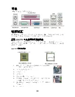
背板


㆒個

PS/2

滑鼠連


㆒個

PS/2

鍵盤連


㆒個序

(COM1) 

㆒個

VGA


㆒個

行埠

支援

SPP/EPP/ECP

模式


㆕個

USB2.0


㆒個

RJ-45

區域

接頭


㆔個或㈥個音

效接頭

(

選配


l


內建接頭


㆓個

USB2.0

接頭


㆒個

CD-In

接頭


㆒個

S/PDIF-out

接頭


㆒個前置面

效接頭


㆒個序

接頭


㆒個

TPM

接頭

(

選配

㆒個

殼開啟警告開

關接頭


㆒個

SPI

除錯

接頭


插槽


l


㆒個

PCI Express x16

插槽


l


㆓個

PCI

插槽


l


支援

3.3V/ 5V PCI

匯流排


尺寸


l

  Micro-ATX (24.4 X 19.3

公分

裝機


l


㈥個裝


㊟意事㊠

您購買的主機板

㆔個音

效接頭,

到㈧聲道音

效,

第㈦

第㈧聲道必須

前置面

(

)

輸出


Summary of Contents for G31M3 V2 Series

Page 1: ...vision reception which can be determined by turning the equipment off and on the user is encouraged to try to correct the interference by one or more of the measures listed below n Reorient or relocat...

Page 2: ...trademarks of International Business Machines Corporation Microsoft is a registered trademark of Microsoft Corporation Windows 98 2000 NT XP are registered trademarks of Microsoft Corporation NVIDIA...

Page 3: ...rting any add on card or module n All cautions and warnings on the equipment should be noted n Never pour any liquid into the opening that could damage or cause electrical shock n If any of the follow...

Page 4: ...la poubelle Les fabricants de ces quipements seront oblig s de r cup rer certains produits en fin de vie MSI prendra en compte cette exigence relative au retour des produits en fin de vie au sein de...

Page 5: ...al nmas iste i ile i birli i i erisinde olacakt r r nlerinizi yerel toplama noktalar na b rakabilirsiniz ESKY Z le n m na ochran ivotn ho prost ed spole nost MSI upozor uje Podle sm rnice Evropsk unie...

Page 6: ...Table of Content English 1 Fran ais 13 Deutsch 25 39 53 65 77...

Page 7: ...are based on Intel G31 Intel ICH7 chipsets for optimal system efficiency Designed to fit the advanced Intel Core TM 2 Duo Core TM 2 Quad Pentium Dual Core E2XXX and Celeron 4XXX Wolfdale Series LGA 7...

Page 8: ...DIMMs 240 pin 1 8V For more information on compatible components please visit http global msi com tw index php func testreport LAN Optional l Supports Realtek RTL8111C 10 100 1000 Mbps l Supports Rea...

Page 9: ...In connector 1 S PDIF Out pinheader 1 Front Panel Audio pinheader 1 serial port connector 1 TPM connector optional 1 chassis intrusion switch pinheader 1 SPI Debugging connector Slots l 1 PCI Express...

Page 10: ...overheating Meanwhile do not forget to apply some thermal paste on CPU before installing the heat sink cooler fan for better heat dispersion Follow the steps below to install the CPU cooler correctly...

Page 11: ...rtant Read the CPU status in BIOS Whenever CPU is not installed always protect your CPU socket pin with the plastic cap covered to avoid damaging Mainboard photos shown in this section are for demonst...

Page 12: ...OK GND GND GND GND 5VSB 12V 12V ATX 12V Power Connector JPW1 This 12V power connector is used to provide power to the CPU GND GND 12V 12V Important Make sure that all the connectors are connected to p...

Page 13: ...ted The system will record this status and show a warning message on the screen To clear the warning you must enter the BIOS utility and clear the record CINTRU GND 2 1 S PDIF Out Connector JSPD1 This...

Page 14: ...platform manual for more details and usages KEY GND GND 14 3Vdual 3V_STB 2 VCC3 SIRQ VCC5 LCLK 1 LRST LAD0 LAD1 LAD2 LAD3 LFRAME 13 Clear CMOS Jumper JBAT1 There is a CMOS RAM onboard that has a power...

Page 15: ...e hardware lines over which devices can send interrupt signals to the microprocessor The PCI IRQ pins are typically connected to the PCI bus pins as follows Order1 Order2 Order3 Order4 PCI Slot1 INT A...

Page 16: ...ry shows the status of your CPU fan warning overall system status BIOS Setting Password Use this menu to set BIOS setting Password Cell Menu Use this menu to specify your settings for frequency voltag...

Page 17: ...tem set to Disable this item will allow you to manually adjust the FSB Ratio of the memory Adjusted DDR Memory Frequency It shows the adjusted DDR Memory frequency Read only Adjust PCI E Frequency MHz...

Page 18: ...please consult your local EMI regulation Remember to disable Spread Spectrum if you are overclocking because even a slight jitter can introduce a temporary boost in clock speed which may just cause yo...

Page 19: ...sur les chipsets Intel G31 et Intel ICH7 offrant un syst me tr s performant La carte fonctionne avec le processeur LGA 775 de Intel Core TM 2 Duo Core TM 2 Quad Pentium Dual Core E2XXX et Celeron 4XXX...

Page 20: ...2 DDR2 DIMMs 240pin 1 8V Pour plus d informations sur les composants compatibles veuillez visiter http global msi com tw index php func testreport LAN Optionnel l Supporte Realtek RTL8111C 10 100 100...

Page 21: ...ecteur CD In 1 connecteur S PDIF Out 1 connecteur audio avant 1 connecteur port s rie 1 connecteur TPM optionnel 1 connecteur chassis intrusion switch 1 connecteur SPI Debugging Slots l 1 slot PCI Exp...

Page 22: ...oss dez pas de syst me de refroidissement contactez votre revendeur pour vous en procurer un et installez le avant d allumer l ordinateur N oubliez pas d utiliser des composants en silicium de transfe...

Page 23: ...ur s assurer que le ventilateur est correctement install Important Lisez les status du CPU dans le BIOS Toujours prot gez les pins de socket du CPU avec le platique de tout domage quand le CPU n est p...

Page 24: ...limentation ATX 12V JPW1 Le connecteur d alimentation 12V est utilis pour alimenter le CPU GND GND 12V 12V Important Assurez vous que tous les connecteurs sont reli s l alimentation ATX pour assurer u...

Page 25: ...necteur de Ch ssis Intrusion JCI1 Ce connecteur est connect un cable chassis intrusion switch Si le ch ssis est ouvert le switch en informera le syst me qui enregistrera ce statut et affichera un cran...

Page 26: ...iques Key no pin SIN DTR DSR CTS DCD SOUT GND RTS RI 10 2 1 9 Connecteur de TPM Module JTPM1 Optionnel Ce connecteur est reli un TPM Trusted Platform Module module optionnel Veuillez vous r f rer au m...

Page 27: ...pour la carte d expansion tel que les cavaliers switches ou la configurations du BIOS PCI Interrupt Request Routing IRQ est l abr viation de interrupt request line Les IRQ sont des signaux mis par des...

Page 28: ...t de l alarme du syst me BIOS Setting Password Utilisez ce menu pour entrer un mot de passe pour le BIOS Cell Menu Utilisez ce menu pour sp cifier votre configuration pour le contr leur de fr quence v...

Page 29: ...r quence de FSB du CPU manuellement Adjusted CPU Frequency Il montre la fr quence du CPU ajust FSB x Ratio Lecture uniquement Advance DRAM Configuration DRAM CAS Latency Ce domaine contr le la latence...

Page 30: ...Enabled pour r duire les interf rences N oubliez pas de d sactiver cette fonction si vous voulez faire de l overclocking parce que la moindre modification peut entra ner une acc l ration temporaire d...

Page 31: ...l G31 Intel ICH7 Chipsatz und erm glicht so ein optimales und effizientes System Entworfen um den hochentwickelten Intel Core TM 2 Duo Core TM 2 Quad Pentium Dual Core E2XXX und Celeron 4XXX Wolfdale...

Page 32: ...den Sie unter http global msi com tw index php func testreport LAN Optional l Unterst tzt Realtek RTL8111C 10 100 1000 Mbps l Unterst tzt Realtek RTL8101E 10 100 Mbps optional l Erf llt die Anforderun...

Page 33: ...n 1 CD Stiftleiste f r Audio Eingang 1 S PDIF Ausgang Stiftleiste 1 Audio Stiftleiste f r Geh use Audio Ein Ausg nge 1 Serielle Stiftleiste 1 TPM Stiftleiste optional 1 Geh usekontaktschalter 1 SPI Be...

Page 34: ...Sie bitte sicher dass Sie auf der CPU einen K hler anbringen um berhitzung zu vermeiden Vergessen Sie nicht etwas Siliziumw rmeleitpaste auf die CPU aufzutragen bevor Sie den Prozessork hler installie...

Page 35: ...11 Drehen Sie das Mainboard um und vergewissern Sie sich dass das der K hler korrekt installiert ist Wichtig Pr fen Sie die Status der CPU im BIOS Wenn keine CPU installiert ist sch tzen Sie immer den...

Page 36: ...3 3V 12V 3 3V 3 3V 3 3V 5V 5V 5V 5V 5V Res PWR OK GND GND GND GND 5VSB 12V 12V ATX 12V Stromanschluss JPW1 Dieser 12V Stromanschluss wird verwendet um die CPU mit Strom zu versorgen GND GND 12V 12V Wi...

Page 37: ...rauchen Sie einen speziellen L fter mit Tacho um diese Funktion zu nutzen GND 12V Sensor Control GND 12V Sensor GND 12V Sensor Geh usekontaktschalter JCI1 Dieser Anschluss wird mit einem Kontaktschalt...

Page 38: ...schnittstelle die 16 Bytes FIFOs senden empf ngt Hier l sst sich eine Serielle Maus oder andere Serielle Ger te direkt anschlie en Key no pin SIN DTR DSR CTS DCD SOUT GND RTS RI 10 2 1 9 TPM Module An...

Page 39: ...SCSI Karte USB Karte und andere Zusatzkarten Karte die mit PCI Spezifikationen bereinstimmen Wichtig Stellen Sie vor dem Einsetzen oder Entnehmen von Karten sicher dass Sie den Netzstecker gezogen hab...

Page 40: ...tenkombination Ctrl Alt und Delete um einen Neustart zu erzwingen Hauptseite Standard CMOS Features In diesem Men k nnen Sie die Basiskonfiguration Ihres Systems anpassen so z B Uhrzeit Datum usw Adva...

Page 41: ...temleistung laden Save Exit Setup Abspeichern der BIOS nderungen im CMOS und verlassen des BIOS Exit Without Saving Verlassen des BIOS ohne Speicherung vorgenommene nderungen verfallen Cell Menu Curre...

Page 42: ...z und stimmt den PCI Express Takt auf eine h here Frequenz Auto Disable DIMM PCI Frequency Lautet die Einstellung auf Enabled eingeschaltet deaktiviert das System die Taktung leerer PCI Sockel um die...

Page 43: ...37 Load Optimized Defaults Hier k nnen Sie die BIOS Voreinstellungen f r den stabilen Betrieb laden die der Mainboardhersteller vorgibt...

Page 44: ...38...

Page 45: ...39 G31M3 V2 MS 7529 v1 x Micro ATX G31M3 V2 Intel G31 Intel ICH7 Intel Core TM 2 Duo Core TM 2 Quad Pentium Dual Core E2XXX LGA 775 Celeron 4XXX Wolfdale G31M3 V2...

Page 46: ...l Intel G31 l Intel ICH7 l DDR2 667 800 SDRAM 4GB Max l 2 DDR2 DIMM 240 1 8V http global msi com tw index php func testreport LAN l Realtek RTL8111C 10 100 1000 l Realtek RTL8101E 10 100 l PCI 2 2 l...

Page 47: ...PM l 1 PS 2 1 PS 2 1 COM1 1 VGA 1 SPP EPP ECP 4 USB 2 0 1 RJ 45 LAN 3 6 l 2 USB 2 0 1 CD In 1 S PDIF Out 1 1 1 TPM 1 1 SPI Debugging l 1 PCI Express x16 l 2 PCI l PCI 3 3V 5V l Micro ATX 24 4 X 19 3 l...

Page 48: ...42 LGA775 LGA 775 LGA 775 LGA 775 1 2...

Page 49: ...43 3 4 5 6 7 8 9 10 11 12 BIOS 1 2 DIMM DIMM DIMM 3 DIMM...

Page 50: ...R DDR2 DDR2 DDR2 DIMM1 24 ATX ATX1 24 ATX 20 GND GND GND PS ON GND 3 3V 12V 3 3V 3 3V 3 3V 5V 5V 5V 5V 5V Res PWR OK GND GND GND GND 5VSB 12V 12V ATX 12 JPW1 12 GND GND 12V 12V ATX 350 ATX 12 18 FDD1...

Page 51: ...ATA4 Serial ATA Serial ATA Serial ATA Serial ATA CPUFAN1 SYSFAN1 SYSFAN2 12 12 GND GND 12V Sensor Control GND 12V Sensor GND 12V Sensor JCI1 BIOS CINTRU GND 2 1 S PDIF Out JSPD1 S PDIF Sony Philips Di...

Page 52: ...VCC USB0 USB0 GND Key no pin 9 JAUD1 Intel Front Panel I O Connectivity Design Guide 2 GND VCC5 MIC2_JD NC 1 MIC_L Line out_R Line out_L 9 Line_JD 10 2 GND MIC_R Front to Sense SPI JSPI1 JCOM1 16550A...

Page 53: ...onnect Express PCI Express PCI Express PCI Express x 16 4 0 PCI Peripheral Component Interconnect PCI LAN SCSI USB PCI BIOS PCI IRQ Interrupt ReQuest line IRQ PCI PCI Order1 Order2 Order3 Order4 PCI S...

Page 54: ...POST DEL DEL SETUP RESET Ctrl Alt Delete Standard CMOS Features Advanced BIOS Features Integrated Peripherals Power Management Setup H W Monitor BIOS Setting Password Cell Menu Load Fail Safe Default...

Page 55: ...etup CMOS Exit Without Saving Cell Menu Current CPU Frequency Current DRAM Frequency Intel EIST Enhanced Intel SpeedStep AC Disabled Speedstep Adjust CPU FSB Frequency Auto Detect CPU Frequency Disabl...

Page 56: ...to Detect DRAM Frequency Disable FSB Adjusted DDR Memory Frequency DRAM Adjust PCI E Frequency MHz PCI Express PCI Express Auto Disable DIMM PCI Frequency Enabled DIMM PCI EMI Spread Spectrum EMI Elec...

Page 57: ...51 BIOS a...

Page 58: ...52...

Page 59: ...53 G31M3 V2 MS 7529 v1 x Micro ATX G31M3 V2 Intel G31 Intel ICH7 LGA775 Intel Core TM 2 Duo Core TM 2 Quad Pentium Dual Core E2XXX Celeron 4XXX Wolfdale G31M3 V2...

Page 60: ...Intel G31 l Intel ICH7 l DDR2 667 800 SDRAM 4 GB l 2 DDR2 DIMM 240 pin 1 8V http global msi com tw index php func testreport LAN l Realtek RTL8111C 10 100 1000 l Realtek RTL8101E 10 100 Mb s l PCI2 2...

Page 61: ...l 1 PS 2 1 PS 2 1 COM1 1 VGA 1 SPP EPP ECP 4 USB 2 0 1 RJ 45 LAN 3 6 l 2 USB2 0 1 CD In 1 SPDIF Out 1 1 1 TPM 1 1 SPI Debugging l 1 PCI Express x 16 l 2 PCI l 3 3V 5V PCI l Micro ATX 24 4 cm X 19 3cm...

Page 62: ...56 CPU LGA775 CPU CPU CPU CPU CPU CPU CPU LGA 775 CPU LGA 775 CPU LGA 775 CPU 1 CPU CPU CPU 2 3 4 5 CPU 6 CPU CPU CPU CPU...

Page 63: ...57 7 CPU CPU 8 9 10 11 12 BIOS CPU CPU CPU CPU 1 2 DIMM DIMM 3 DIMM Volt Notch...

Page 64: ...0 pin ATX 1 13 11 12 23 24 GND GND GND PS ON GND 3 3V 12V 3 3V 3 3V 3 3V 5V 5V 5V 5V 5V Res PWR OK GND GND GND GND 5VSB 12V 12V ATX 12V JPW1 12V CPU GND GND 12V 12V ATX 350 ATX 12V 18A FDD1 360KB 720K...

Page 65: ...CD ROM GND L R JFP2 Power LED Speaker 2 8 1 7 JFP1 JFP2 JFP2 Intel I O JFP1 HDD LED Reset Switch Power Switch Power LED 1 9 10 2 USB JUSB1 JUSB2 Intel I O USB USB MP3 N C 10 2 VCC USB1 USB1 GND 1 VCC...

Page 66: ...Platform Module TPM KEY GND GND 14 3Vdual 3V_STB 2 VCC3 SIRQ VCC5 LCLK 1 LRST LAD0 LAD1 LAD2 LAD3 LFRAME 13 CMOS JBAT1 CMOS RAM CMOS RAM CMOS RAM JBAT1 CMOS Keep Data Clear Data 2 2 2 3 3 3 1 1 1 2 3...

Page 67: ...Slot1 INT A INT B INT C INT D PCI Slot2 INT B INT C INT D INT A BIOS POST DEL Press DEL to enter SETUP Setup RESET Ctrl Alt Delete Standard CMOS Features CMOS Advanced BIOS Features BIOS Integrated P...

Page 68: ...Setting Password BIOS BIOS Cell Menu Load Fail Safe Defaults BIOS Load Optimized Defaults BIOS Save Exit Setup CMOS Setup Exit Without Saving CMOS Setup Current CPU Frequency CPU CPU Current DRAM Fre...

Page 69: ...DRAM 2T 2 5T By SPD DRAM CAS BIOS DRAM SPD Serial Presence Detect EEPROM FSB Memory Ratio Auto Detect DRAM Frequency Disable FSB Ratio Adjusted DDR Memory Frequency DRAM Adjust PCI E Frequency MHz PCI...

Page 70: ...64...

Page 71: ...65 G31M3 V2 MS 7529 v1 X Micro ATX G31M3 V2 Intel G31 Intel ICH7 LGA775 Intel Core TM 2 Duo Core TM 2 Quad Pentium Dual Core E2XXX Celeron 4XXX Wolfdale G31M3 V2...

Page 72: ...B 800 1066 1333 MHz l Intel G31 l Intel ICH7 l DDR2 667 800 SDRAM 4GB l 2 DDR2 DIMM 240pin 1 8V http global msi com tw index php func testreport LAN l Realtek RTL8101E 10 100 Mb l Realtek RTL8111C 10...

Page 73: ...67 l l 360KB 720KB 1 2MB 1 44MB 2 88MB TPM l TPM l PS 2 PS 2 COM1 VGA SPP EPP ECP USB2 0 RJ 45 l USB2 0 CD In S PDIF out TPM SPI l PCI Express x16 l PCI l 3 3V 5V PCI l Micro ATX 24 4 X 19 3 l...

Page 74: ...68 LGA775 LGA775 LGA775 CPU LGA775 CPU 1 CPU CPU CPU 2 3 4 5 6 CPU 7 CPU CPU 8 Pin1 Pin1...

Page 75: ...69 9 10 11 12 BIOS CPU CPU CPU 1 2 DIMM 3 DIMM Volt Notch DDR2 DDR DDR DDR2 DDR2 DIMM1...

Page 76: ...D GND PS ON GND 3 3V 12V 3 3V 3 3V 3 3V 5V 5V 5V 5V 5V Res PWR OK GND GND GND GND 5VSB 12V 12V ATX 12V JPW1 12V CPU GND GND 12V 12V ATX 350 ATX 12V 18 FDD1 360 KB 720 KB 1 2 MB 1 44 MB 2 88 MB IDE IDE...

Page 77: ...nnect Format GND VCC SPDIF CD In CD_IN1 GND L R JFP2 Power LED Speaker 2 8 1 7 JFP1 JFP2 LED JFP1 Intel I O JFP1 HDD LED Reset Switch Power Switch Power LED 1 9 10 2 USB JUSB1 JUSB2 Intel I O USB USB...

Page 78: ...I 10 2 1 9 TPM JTPM1 KEY GND GND 14 3Vdual 3V_STB 2 VCC3 SIRQ VCC5 LCLK 1 LRST LAD0 LAD1 LAD2 LAD3 LFRAME 13 CMOS JBAT1 CMOS RAM CMOS RAM Keep Data Clear Data 2 2 2 3 3 3 1 1 1 2 3 CMOS 1 2 CMOS PCI E...

Page 79: ...CI Order1 Order2 Order3 Order4 PCI Slot1 INT A INT B INT C INT D PCI Slot2 INT B INT C INT D INT A BIOS POST DEL Press DEL to enter SETUP RESET Ctrl Alt Delete Standard CMOS Features CMOS Advanced BIO...

Page 80: ...H W Monitor BIOS Setting Password BIOS BIOS Cell Menu Load Fail Safe Defaults BIOS Load Optimized Defaults BIOS Save Exit Setup CMOS Exit Without Saving Cell Menu Current CPU Frequency CPU CPU Curren...

Page 81: ...CPU FSB x Ratio Advance DRAM Configuration DRAM CAS Latency DRAM 2T 2 5T By SPD BIOS DRAM SPD EEPROM DRAM FSB Memory Ratio FSB Ratio FSB Ratio Adjusted DDR Memory Frequency Adjust PCI E Frequency MHz...

Page 82: ...76...

Page 83: ...77 G31M3 V2 MS 7529 v1 x Micro ATX G31M3 V2 Intel G31 Intel ICH7 LGA 775 Intel Core TM 2 Duo Core TM 2 Quad Pentium Dual Core E2XXX Celeron 4XXX Wolfdale...

Page 84: ...orm FSB l 800 1066 1333 MHz l Intel G31 l Intel ICH7 l DDR2 667 800 SDRAM 4GB l 2 DDR2 DIMMs 240 1 8V http global msi com tw index php func testreport LAN l Realtek RTL8111C 10 100 1000 Mbps l Realtek...

Page 85: ...44MB 2 88MB FDD 1 TPM l TPM l 1 PS 2 1 PS 2 1 COM1 1 VGA 1 SPP EPP ECP 4 USB 2 0 1 RJ 45 LAN 3 6 l 2 USB 2 0 1 CD In 1 S PDIF Out 1 1 1 TPM 1 1 SPI l PCI Express x16 l PCI 2 l 3 3V 5V PCI l Micro ATX...

Page 86: ...80 LGA775 CPU CPU CPU CPU CPU CPU CPU LGA 775 CPU LGA 775 CPU LGA 775 CPU 1 CPU 2 CPU 3 CPU 4...

Page 87: ...81 5 6 CPU CPU 7 CPU 8 9 10 CPU 11 12 CPU BIOS CPU CPU CPU 1 2 DIMM DIMM DIMM 3 DIMM Volt Notch...

Page 88: ...D GND GND PS ON GND 3 3V 12V 3 3V 3 3V 3 3V 5V 5V 5V 5V 5V Res PWR OK GND GND GND GND 5VSB 12V 12V ATX 12V JPW1 12V CPU GND GND 12V 12V 350W ATX 12V 18A FDD FDD1 360 KB 720 KB 1 2MB 1 44MB 2 88MB IDE...

Page 89: ...hilips Digital Interconnect Format GND VCC SPDIF CD In CD_IN1 GND L R JFP2 Power LED Speaker 2 8 1 7 JFP1 JFP2 LED JFP1 Intel Front Panel I O Connectivity Design Guide JFP1 HDD LED Reset Switch Power...

Page 90: ...IFO Key no pin SIN DTR DSR CTS DCD SOUT GND RTS RI 10 2 1 9 TPM JTPM1 TPM Trusted Platform Module TPM KEY GND GND 14 3Vdual 3V_STB 2 VCC3 SIRQ VCC5 LCLK 1 LRST LAD0 LAD1 LAD2 LAD3 LFRAME 13 CMOS JBAT1...

Page 91: ...nterrupt request line PCI IRQ PCI INT A INT D Order1 Order2 Order3 Order4 PCI Slot1 INT A INT B INT C INT D PCI Slot2 INT B INT C INT D INT A BIOS POST Power On Self Test DEL Press DEL to enter SETUP...

Page 92: ...dvanced BIOS Features Integrated Peripherals IDE I O Power Management Setup H W Monitor CPU BIOS Setting Password Cell Menu Load Fail Safe Defaults BIOS Load Optimized Defaults BIOS Save Exit Setup CM...

Page 93: ...ep PC AC CPU Disabled CPU Adjust CPU FSB Frequency MHz Auto Detect CPU Frequency Disable CPU FSB Adjusted CPU Frequency CPU FSB x CPU Advance DRAM Configuration DRAM CAS Latency DRAM CAS 2 5T 2T By SP...

Page 94: ...uency DRAM Adjust PCI E Frequency MHz PCIE MHz Auto Disable DIMM PCI Frequency Enabled DIMM PCI EMI Spread Spectrum EMI Disabled Spread Spectrum Enabled Disabled Disabled Enabled Spread Spectrum Disab...

Page 95: ...Pb Hg Cd Cr VI PBB PBDE PCB O SJ T11363 2006 X SJ T11363 2006 0 35 0 4 4 85 pins microprocessors 80 85 Flip Chippackages...

Reviews: