background image

3

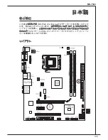
MS-7592

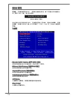
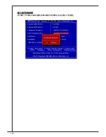
BioS Setting Password ( 設定 BioS 密碼 )

使用本選單設定 BioS 密碼。
Cell menu

本選單可指定頻率及電壓控制。
m-Flash

使用本選單由 uSB 多媒體儲存裝置讀取或 flash BioS。
Load Fail-Safe defaults ( 載入安全預設值 )

本選單載入 BioS 出廠預設值。
Load optimized defaults ( 載入最佳預設值 )

使用本選單載入 BioS 的最佳預設值,以獲穩定的系統效能。
Save & exit Setup ( 儲存並離開設定 )

將變更儲存到 CmoS,並離開設定程式。
exit Without Saving ( 離開但不儲存 )

放棄所有變更並離開設定程式。

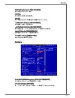
Cell menu

Current CPu/dRam Frequency ( 目前 CPu / 記憶體頻率 )

本項顯示目前的 CPu 及記憶體頻率。唯讀。
CPu Specifications (CPu 規格)

按下 <enter> 鍵,即可進入子選單。子選單顯示已安裝 CPu 訊息。

Summary of Contents for G41M-P34

Page 1: ...erence by one or more of the measures listed below Reorient or relocate the receiving antenna Increase the separation between the equipment and receiver Connect the equipment into an outlet on a circu...

Page 2: ...emark of NVIDIA Corporation ATI is registered trademark of ATI Technologies Inc AMD is registered trademarks of AMD Corporation Intel is registered trademarks of Intel Corporation Windows is registere...

Page 3: ...on the equipment should be noted Never pour any liquid into the opening that could damage or cause electri cal shock If any of the following situations arises get the equipment checked by service pers...

Page 4: ...ommunale Abf lle entsorgt werden MSI hat europaweit verschiedene Sammel und Recyclingunternehmen beauftragt die in die Europ ische Union in Verkehr gebrachten Produkte am Ende seines Lebenszyklus zur...

Page 5: ...o ducten die de merknaam MSI dragen en verkocht zijn in de EU Deze goederen kunnen geretourneerd worden op lokale inzamelingspunten SRPSKI Da bi za titili prirodnu sredinu i kao preduze e koje vodi ra...

Page 6: ...MAGYAR Annak rdek ben hogy k rnyezet nket megv dj k illetve k rnyezetv d k nt fell pve az MSI eml kezteti nt hogy Az Eur pai Uni EU 2005 augusztus 13 n hat lyba l p az elektromos s elektronikus beren...

Page 7: ...2 BIOS Setup 22 27 27 28 30 30 BIOS 40 Fran ais 45 Pour commencer 45 SP CIFICATIONS 46 panneau arri re 48 Installation du mat riel 48 R glage bios 58 DEUTSCH 63 eINLEITUNG 63 SPEZIFIKATIONEN 64 Hinter...

Page 8: ...117 117 118 120 120 BIOS 130 135 135 136 I O 138 138 BIOS 148...

Page 9: ...X mainboard The G41M P34 is based on Intel G41 ICH7 ICH7R chipset for optimal system efficiency Designed to fit the advanced Intel Core 2 Quad Core 2 Duo Pen tium Celeron processor in LGA775 package t...

Page 10: ...e components please visit http www msi com index php func testreport LAN Supports LAN 10 100 1000 Fast Ethernet by Atheros AR8131M Audio VIA VT1828S 7 1 channel audio codec Compliant with Azalia 1 0 S...

Page 11: ...parallel port connector 1 TPM connector Slots 1 PCI Express x1 slot 1 PCI Express x16 slot 1 PCI slot supports 3 3V 5V PCI bus Interface Form Factor Micro ATX 200mm x 245mm Mounting 6 mounting holes...

Page 12: ...installation be careful in holding the components and follow the installation procedures CPU Cooler Installation Procedures for LGA775 When you are installing the CPU make sure that you install the c...

Page 13: ...Cover the load plate onto the package Press down the load lever lightly onto the load plate and then secure the lever with the hook under the retention tab Align the holes on the mainboard with the he...

Page 14: ...DIMM slot will automatically close when the memory module is properly seated You can barely see the gold en finger if the memory module is properly inserted in the DIMM slot Manually check if the mem...

Page 15: ...n d 1 8 G r o u n d 6 5 V 1 9 G r o u n d 7 G r o u n d 2 2 5 V 1 0 1 2 V 2 0 R e s 8 P W R O K 2 3 5 V 1 1 1 2 V 2 1 5 V 9 5 V S B 2 4 G r o u n d 1 2 3 3 V ATX 4 Pin Power Connector JPWR2 This 4 Pin...

Page 16: ...l ATA device Important Please do not fold the Serial ATA cable into 90 degree angle Otherwise data loss may occur during transmission Fan Power Connectors CPUFAN1 SYSFAN1 SYSFAN2 The fan power connect...

Page 17: ...tion to the front panel switches and LEDs The JFP1 is compliant with Intel Front Panel I O Connectivity Design Guide 1 3 1 0 N o P i n 5 R e s e t S w i t c h H D D L E D P o w e r S w i t c h P o w e...

Page 18: ...ce peripherals such as USB HDD digital cameras MP3 players printers modems and the like 1 V C C 3 U S B D 1 0 U S B O C 5 U S B D 7 G r o u n d 9 N o P i n 8 G r o u n d 6 U S B D 4 U S B D 2 V C C TP...

Page 19: ...upports Enhanced Parallel Port EPP and Extended Capabilities Parallel Port ECP mode 1 0 G r o u n d 1 4 G r o u n d 8 L P T _ S L I N 1 2 G r o u n d 6 P I N I T 4 E R R 2 A F D 2 4 G r o u n d 2 2 G...

Page 20: ...shorting 2 3 pin while the system is off Then return to 1 2 pin position Avoid clearing the CMOS while the system is on it will damage the mainboard Overclock FSB Switch OC_SW1 You can overclock the F...

Page 21: ...at you unplug the power supply first Meanwhile read the documentation for the expansion card to configure any necessary hardware or software settings for the expansion card such as jumpers switches or...

Page 22: ...the system by simultaneously pressing Ctrl Alt and Delete keys Main Page Standard CMOS Features Use this menu for basic system configurations such as time date etc Advanced BIOS Features Use this men...

Page 23: ...lt values that are factory settings for sys tem operations Load Optimized Defaults Use this menu to load factory default settings into the BIOS for stable system performance operations Save Exit Setup...

Page 24: ...determined by BIOS based on the configurations on the SPD Selecting Manual allows users to configure the DRAM timings and the following related items manually CAS Latency CL When the DRAM Timing Mode...

Page 25: ...st valid write operation and the next read command to the same internal bank of the DDR device FSB DRAM Ratio This item will allow you to adjust the ratio of FSB to memory Adjusted DRAM Frequency MHz...

Page 26: ...the EMI is reduced and the system will become less stable For the most suitable Spread Spectrum value please consult your local EMI regulation Remember to disable Spread Spectrum if you are overclocki...

Page 27: ...27 MS 7592 G41M P34 MS 7592 v5 x G41M P34 Intel G41 ICH7 ICH7R LGA775 Intel Core 2 Quad Core 2 Duo Pentium Celeron G41M P34...

Page 28: ...3 OC 1066 800 DIMM 2 8GB http www msi com index php func testreport LAN Atheros AR8131M LAN 10 100 1000 Fast Ethernet VIA VT1828S 7 1 Azalia 1 0 Spec IDE Intel ICH7 ICH7R IDE 1 Ultra DMA 66 100 PIO SA...

Page 29: ...29 MS 7592 USB 2 0 2 S PDIF 1 CD 1 1 1 1 1 TPM 1 PCI Express x1 1 PCI Express x16 1 PCI 1 3 3V 5V PCI Micro ATX 200mm x 245mm 6 http www msi com index php...

Page 30: ...30 LGA 775 CPU LGA 775 CPU CPU LGA775 CPU CPU 1 1 VGA HDMI USB LAN USB RS CS SS...

Page 31: ...31 MS 7592 CPU CPU CPU CPU CPU CPU CPU CPU CPU 4 4 CPU CPU BIOS CPU CPU CPU CPU 2 3 4 5 6 7 8 9 0 2 3...

Page 32: ...32 DIMM DIMM DIMM DIMM DIMM 2 3 DIMM DIMM1...

Page 33: ...S O N 4 5 V 1 7 G r o u n d 5 G r o u n d 1 8 G r o u n d 6 5 V 1 9 G r o u n d 7 G r o u n d 2 2 5 V 1 0 1 2 V 2 0 R e s 8 P W R O K 2 3 5 V 1 1 1 2 V 2 1 5 V 9 5 V S B 2 4 G r o u n d 1 2 3 3 V ATX...

Page 34: ...4 IDE IDE1 IDE IDE 2 IDE IDE ATA SATA1 4 ATA ATA ATA 90 CPUFAN1 SYSFAN1 SYSFAN2 12V 12V GND CPU 1 G r o u n d 2 1 2 V 3 S e n s o r 1 G r o u n d 2 1 2 V 3 S e n s o r 4 C o n t r o l CPUFAN1 SYSFAN1...

Page 35: ...L JFP1 JFP2 LED JFP1 Intel Front Panel I O Connectivity Design Guide 1 3 1 0 N o P i n 5 R e s e t S w i t c h H D D L E D P o w e r S w i t c h P o w e r L E D 7 9 R e s e r v e d 8 6 4 2 JFP1 1 G r...

Page 36: ...SB HDD MP3 USB 1 V C C 3 U S B D 1 0 U S B O C 5 U S B D 7 G r o u n d 9 N o P i n 8 G r o u n d 6 U S B D 4 U S B D 2 V C C TPM JTPM1 TPM Trusted Platform Module TPM 1 0 N o P i n 1 4 G r o u n d 8 5...

Page 37: ...4 E R R 2 A F D 2 4 G r o u n d 2 2 G r o u n d 2 6 N o P i n 2 0 G r o u n d 1 8 G r o u n d 1 6 G r o u n d 1 R S T B 3 P R N D 0 5 P R N D 1 7 P R N D 2 9 P R N D 3 1 1 P R N D 4 1 3 P R N D 5 1 5...

Page 38: ...38 CMOS JBAT1 CMOS RAM CMOS RAM OS 1 1 1 JBAT1 2 3 CMOS 1 2 CMOS FSB OC_SW1 FSB FSB 200 266 MHz 200 333 MHz 266 333 MHz 200 400 MHz 266 400 MHz 333 400 MHz...

Page 39: ...39 MS 7592 PCI Express PCI Express PCI Express PCI Express x16 PCI Express x1 PCI PCI LAN SCSI USB PCI BIOS PCI Interrupt request line IRQ I R Q PCI IRQ PCI 1 2 3 4 PCI 1 INT A INT B INT C INT D...

Page 40: ...wer On Self Test DEL RESET Ctrl Alt Delete Main Page Standard CMOS Features CMOS Advanced BIOS Features BIOS Integrated Peripherals Power Management Setup H W Monitor H W CPU Green Power Press DEL to...

Page 41: ...BIOS BIOS Cell Menu M Flash M USB mediaevice BIOS Load Fail Safe Defaults BIOS Load Optimized Defaults BIOS Save Exit Setup CMOS Exit Without Saving Cell Menu Current CPU DRAM Frequency CPU DRAM CPU...

Page 42: ...ncy CPU MHz CPU FSB x Ratio MEMORY Z Z Enter DIMM1 2 Memory SPD Information DIMM1 2 SPD Enter Advance DRAM Configuration DRAM Enter DRAM Timing Mode DRAM DRAM SPD EEPROM DRAM Auto By SPD SPD BIOS DRAM...

Page 43: ...rite Data In to Read Command Delay DDR FSB DRAM Ratio FSB DRAM FSB Adjusted DRAM Frequency DRAM MHz Adjust PCI E Frequency PCI E MHz PCI E Auto Disable DRAM PCI Frequency DRAM PCI Enabled DRAM PCI EMI...

Page 44: ...44 EMI EMI EMI EMI EMI Load Optimized Defaults...

Page 45: ...s G41M P34 sont bas es sur les puces Intel G41 ICH7 ICH7R offrant un syst me tr s performant La carte fonctionne avec les processeurs Intel Core 2 Quad Core 2 Duo Pentium Celeron avanc s dans le paque...

Page 46: ...ants compatibles veuillez visiter http www msi com index php func testreport LAN Supporte LAN 10 100 1000 Fast Ethernet par Atheros AR8131M Audio VIA VT1828S 7 1 canaux audio codec Compatible avec les...

Page 47: ...le 1 connecteur TPM Emplacements 1 emplacement PCI Express x1 1 emplacement PCI Express x16 1 emplacement PCI supporte l Interface bus PCI 3 3V 5V Dimension Micro ATX 200mm x 245mm Montage 6 trous de...

Page 48: ...r etc Lors de l installation du mat riel veuillez suivre les instructions de montage pour viter d endommager quoi que ce soit Proc dure d intallation du CPU et le ventilateur pour LGA775 Quand vous in...

Page 49: ...de charge sur le paquet Abaissez le levier sur le plateau de chargemen puis s curiser l ensemble avec le m canisme de r tention Alignez les trous de la carte avec le ventilateur Installez le ventilate...

Page 50: ...e clip en plastique situ de chaque c t du module va se fermer automatiquement Vous ne opuvez presque pas voir le doigt d or si le module de m moire est correctement ins r dans le slot DIMM Les clips e...

Page 51: ...o u n d 6 5 V 1 9 G r o u n d 7 G r o u n d 2 2 5 V 1 0 1 2 V 2 0 R e s 8 P W R O K 2 3 5 V 1 1 1 2 V 2 1 5 V 9 5 V S B 2 4 G r o u n d 1 2 3 3 V Connecteur d alimentation ATX 4 pin JPWR2 Ce connecteu...

Page 52: ...se connecter un dispositif S rial ATA Important Veuillez ne pas tordre le c ble S rial ATA 90 degr s Cela pourrait l endommager et entrainer la perte de donn es lors des phases de transfert de celles...

Page 53: ...iques aux cummutateurs et LEDs Le JFP1 est compatible ave Intel Front Panel I O Connectivity Design Guide 1 3 1 0 N o P i n 5 R e s e t S w i t c h H D D L E D P o w e r S w i t c h P o w e r L E D 7...

Page 54: ...de haute vitesse tel que USB HDD cam ra num rique lecteur MP3 imprimants modems et etc 1 V C C 3 U S B D 1 0 U S B O C 5 U S B D 7 G r o u n d 9 N o P i n 8 G r o u n d 6 U S B D 4 U S B D 2 V C C Con...

Page 55: ...Enhanced Parallel Port EPP et Extended Capabilities Parallel Port ECP 1 0 G r o u n d 1 4 G r o u n d 8 L P T _ S L I N 1 2 G r o u n d 6 P I N I T 4 E R R 2 A F D 2 4 G r o u n d 2 2 G r o u n d 2 6...

Page 56: ...lorsque le PC n est pas allum Puis il faut remettre le cavalier en position 1 2 pin Evitez surtout d effacer le CMOS lorsque le PC est allum cela endommagera la carte m re Interrupteur du FSB d Overcl...

Page 57: ...tension assurez vous que le PC n est pas reli au secteur Lisez le documentation pour faire les configurations n cessaires du mat riel ou du logiciel de la carte d extension tels que cavaliers commutat...

Page 58: ...elete Page Principale Standard CMOS Features Utilisez ce menu pour param trer des l ments standards du BIOS tel que l heure la date etc Advanced BIOS Features Utilisez ce menu pour r gler les articles...

Page 59: ...ges de la manufacture pour l op ration du syst me Load Optimized Defaults Utilisez ce menu pour charger les r glages par d faut de la manufacture dans le BIOS pour meilleure performance op ration Save...

Page 60: ...r les configurations du SPD La mise en Manual vous permet de config urer le DRAM timings et les articles relatifs suivants manuellement CAS Latency CL Lorsque le DRAM Timing Mode est mis en Manual ce...

Page 61: ...tion valide d criture et l ordre de lecture suivant la m me banque internal du p riph rique DDR FSB DRAM Ratio Cet article vous permet d ajuster le ratio du FSB la m moire Adjusted DRAM Frequency MHz...

Page 62: ...es et le syst me devient moins stable Pour la valeur Spread Spectrum la plus convenable veuillez consulter le r glement EMI local N oubliez pas de d sactiver la fonction Spread Spectrum si vous tes en...

Page 63: ...uf dem Intel G41 ICH7 ICH7R Chipsatz und erm glicht so ein optimales und effizientes System Entworfen um den hochent wickelten Intel Core 2 Quad Core 2 Duo Pentium Celeron Prozessoren f r Sockel LGA77...

Page 64: ...msi com index php func testreport LAN Unterst tzt LAN 10 100 1000 Fast Ethernet ber Atheros AR8131M Audio VIA VT1828S 7 1 Kanal Audio Codec Erf llt die Azalia Spezifikationen IDE 1 IDE Port ber Intel...

Page 65: ...halter 1 serieller Anschluss 1 parallelle Schnittstelle 1 TPM Schnittstelle Steckpl tze 1 PCI Express x1 Steckplatz 1 PCI Express x16 Steckplatz 1 PCI Steckplatz unterst tzt 3 3V 5V PCI Bus Interface...

Page 66: ...n wie z B Maus Tastatur usw Handha ben Sie die Komponenten w hrend des Einbaus vorsichtig und halten Sie sich an die vorgegebene Vorgehensweise beim Einbau CPU K hler Einbau f r Sockel LGA775 Wenn Sie...

Page 67: ...g des Sockels Dr cken Sie den Verschlusshebel mit leichtem Druck nach unten und arretieren Sie den Hebel un ter dem R ckhaltehaken des CPU Sockels F hren Sie den CPU K hler ber den CPU Sockel und posi...

Page 68: ...Ende des DIMM Steckplatzes schnappt automatisch ein wenn das Arbeitsspeichermodul richtig eingesetzt ist Die goldenen Kon takte sind kaum zu sehen wenn das Arbeitsspeichermodul richtig im DIMM Steckpl...

Page 69: ...n d 7 G r o u n d 2 2 5 V 1 0 1 2 V 2 0 R e s 8 P W R O K 2 3 5 V 1 1 1 2 V 2 1 5 V 9 5 V S B 2 4 G r o u n d 1 2 3 3 V ATX 4 poliger Stromanschluss JPWR2 Dieser Stromanschluss wird verwendet um die...

Page 70: ...geschlos sen werden Wichtig Bitte falten Sie das Serial ATA Kabel nicht in einem Winkel von 90 Grad da dies zu Datenverlusten w hrend der Daten bertragung f hrt Stromanschl sse f r L fter CPUFAN1 SYSF...

Page 71: ...s des Frontpaneels JFP1 erf llt die Anforderungen des Intel Front Panel I O Connectivity Design Guide 1 3 1 0 N o P i n 5 R e s e t S w i t c h H D D L E D P o w e r S w i t c h P o w e r L E D 7 9 R...

Page 72: ...geeignet Hochgeschwindigkeits USB Periph erieger te anzuschlie en wie z B USB Festplattenlaufwerke Digitalkameras MP3 Player Drucker Modems und hnliches 1 V C C 3 U S B D 1 0 U S B O C 5 U S B D 7 G r...

Page 73: ...Port unterst tzt die Betriebsmodi EPP Enhanced Parallel Port und ECP Ex tended Capabilities Port 1 0 G r o u n d 1 4 G r o u n d 8 L P T _ S L I N 1 2 G r o u n d 6 P I N I T 4 E R R 2 A F D 2 4 G r...

Page 74: ...en w hrend das System ausgeschaltet ist Kehren Sie danach zur Pinposition 1 2 zur ck L schen Sie den CMOS nicht solange das System angeschaltet ist dies w rde das Mainboard besch digen Hardware bertak...

Page 75: ...zie hen bevor Sie eine Erweiterungskarte installieren oder entfernen Denken Sie bitte auch daran die Dokumentation der Erweiterungskarte zu lesen um not wendige Hardware oder Softwareeinstellungen f r...

Page 76: ...iv bet tigen Sie die Tastenkombination Ctrl Alt und Delete um einen Neustart zu erzwingen Main Page Standard CMOS Features In diesem Men k nnen Sie die Basiskonfiguration Ihres Systems anpassen so z B...

Page 77: ...rieb abtasten aufblinken nur FAT FAT32 Format Load Fail Safe Defaults Hier k nnen Sie die BIOS Werkseinstellungen f r stabile Systemleistung laden Load Optimized Defaults In diesem Men k nnen Sie eine...

Page 78: ...n Sie aus ob DRAM Timing durch das SPD Serial Presence Detect EEPROM auf dem DRAM Modul gesteuert wird Die Einstellung Auto By SPD erm glicht die automatische Erkennung des DRAM timings durch das BIOS...

Page 79: ...uffern werden k nnen zu den Speicherzellen ge schrieben bevor Vor Aufladung auftritt tRRD Lautet die Einstellung unter DRAM Timing Manual k nnen Sie hier die DRAM Timing angeben Diese Option legt die...

Page 80: ...n die gerade ausreichen mag um Ihren bertakteten Prozessor zum einfrieren zu bringen Wichtig Sollten Sie keine Probleme mit Interferenzen haben belassen Sie es bei der Einstellung Disabled ausgeschalt...

Page 81: ...81 MS 7592 G41M P34 MS 7592 v5 x Micro ATX G41M P34 Intel G41 ICH7 ICH7R Intel Core 2 Quad Core 2 Duo Pentium Celeron LGA775...

Page 82: ...1333 OC 1066 800 DIMM 8 Max http www msi com index php func testreport LAN LAN 10 100 1000 Fast Ethernet Atheros AR8131M VIA VT1828S 7 1 Azalia 1 0 IDE 1 IDE Intel ICH7 ICH7R Ultra DMA 66 100 PIO Bus...

Page 83: ...83 MS 7592 1 LAN 6 2 USB 2 0 1 S PDIF Out 1 CD In 1 1 1 1 1 TPM 1 PCI Express x1 1 PCI Express x16 1 PCI PCI 3 3V 5V Micro ATX 200 x 245 6 http www msi com index php...

Page 84: ...84 LGA 775 LGA 775 LGA775 1 1 VGA HDMI USB LAN USB RS CS SS...

Page 85: ...85 MS 7592 BIOS 2 3 4 5 6 7 8 9 0 2 3...

Page 86: ...86 DIMM DIMM DIMM DIMM DIMM 2 3 DIMM1...

Page 87: ...6 P S O N 4 5 V 1 7 G r o u n d 5 G r o u n d 1 8 G r o u n d 6 5 V 1 9 G r o u n d 7 G r o u n d 2 2 5 V 1 0 1 2 V 2 0 R e s 8 P W R O K 2 3 5 V 1 1 1 2 V 2 1 5 V 9 5 V S B 2 4 G r o u n d 1 2 3 3 V...

Page 88: ...E master slave Serial ATA SATA1 4 Serial ATA Serial ATA Serial ATA Serial ATA CPUFAN1 SYSFAN1 SYSFAN2 12 12 GND 1 G r o u n d 2 1 2 V 3 S e n s o r 1 G r o u n d 2 1 2 V 3 S e n s o r 4 C o n t r o l...

Page 89: ...Front Panel I O Connectiv ity Design Guide 1 3 1 0 N o P i n 5 R e s e t S w i t c h H D D L E D P o w e r S w i t c h P o w e r L E D 7 9 R e s e r v e d 8 6 4 2 JFP1 1 G r o u n d 3 S u s p e n d L...

Page 90: ...USB HDD MP3 1 V C C 3 U S B D 1 0 U S B O C 5 U S B D 7 G r o u n d 9 N o P i n 8 G r o u n d 6 U S B D 4 U S B D 2 V C C TPM JTPM1 TPM Trusted Platform Module TPM 1 0 N o P i n 1 4 G r o u n d 8 5 V...

Page 91: ...I N I T 4 E R R 2 A F D 2 4 G r o u n d 2 2 G r o u n d 2 6 N o P i n 2 0 G r o u n d 1 8 G r o u n d 1 6 G r o u n d 1 R S T B 3 P R N D 0 5 P R N D 1 7 P R N D 2 9 P R N D 3 1 1 P R N D 4 1 3 P R N...

Page 92: ...92 CMOS JBAT1 CMOS CMOS CMOS 1 1 1 JBAT1 CMOS 2 3 1 2 CMOS FSB OC_SW1 FSB FSB 200 266 200 333 266 333 200 400 266 400 333 400...

Page 93: ...93 MS 7592 PCI Express PCI Express PCI Express PCI Express x16 PCI Express x1 PCI PCI LAN SCSI USB PCI BIOS PCI IRQ interrupt request line PCI IRQ PCI Order Slot 1 2 3 4 PCI 1 INT A INT B INT C INT D...

Page 94: ...POST DEL Press DEL to enter SETUP DEL SETUP RESET Ctrl Alt Delete Main Page Standard CMOS Features CMOS Advanced BIOS Features BIOS BIOS Integrated Peripherals Power Management Setup H W Monitor Gree...

Page 95: ...ing Password BIOS Cell Menu Cell M Flash BIOS USB mediaevice Load Fail Safe Defaults BIOS Load Optimized Defaults Save Exit Setup CMOS Exit Without Saving Cell Menu Current CPU DRAM Frequency CPU Spec...

Page 96: ...tio MEMORY Z Enter DIMM1 2 Memory SPD Information Enter Advance DRAM Configuration Enter DRAM Timing Mode DRAM SPD Serial Presence Detect EEPROM DRAM Auto By SPD DRAM BIOS SPD Manual DRAM CAS Latency...

Page 97: ...FC tWR DRAM Timing Mode Manual tRRD DRAM Timing Mode Manual tWTR DRAM Timing Mode Manual Write Data In Read Command Delay DDR FSB DRAM Ratio FSB Adjusted DRAM Frequency Adjust PCI E Frequency PCI E Au...

Page 98: ...98 Spread Spectrum EMI Electromagnetic Interference Spread Spectrum Dis abled Enable Spread Spectrum Disabled Spread Spec trum Spread Spectrum SpreadSpectrum Spread Spectrum BIOS...

Page 99: ...99 MS 7592 G41M P34 MS 7592 v5 x Micro ATX G41M P34 Intel G41 ICH7 ICH7R LGA775 Intel Core 2 Quad Core 2 Duo Pentium Celeron G41M P34...

Page 100: ...ICH7R 2 DDR3 1333 OC 1066 800 DIMM 8GB http www msi com index php func testreport LAN Atheros AR8131M 10 100 1000 VIA VT1828S 7 1 Azalia 1 0 IDE Intel ICH7 ICH7R 1 IDE Ultra DMA 66 100 PIO SATA Intel...

Page 101: ...101 MS 7592 2 USB 2 0 1 S PDIF Out 1 CD In 1 1 1 1 1 TPM 1 PCI Express x1 1 PCI Express x16 1 PCI 3 3V 5V Micro ATX 200mm x 245mm 6 http www msi com index php...

Page 102: ...102 LGA 775 CPU LGA 775 CPU CPU CPU LGA775 CPU CPU CPU CPU Pin1 Pin1 VGA HDMI USB LAN USB Line In Line Out MIC RS Out CS Out SS Out...

Page 103: ...103 MS 7592 CPU CPU CPU CPU CPU CPU CPU CPU CPU CPU CPU CPU CPU CPU BIOS CPU CPU CPU CPU 2 3 4 5 6 7 8 9 0 2 3...

Page 104: ...104 DIMM 2 3 DIMM1...

Page 105: ...1 6 P S O N 4 5 V 1 7 G r o u n d 5 G r o u n d 1 8 G r o u n d 6 5 V 1 9 G r o u n d 7 G r o u n d 2 2 5 V 1 0 1 2 V 2 0 R e s 8 P W R O K 2 3 5 V 1 1 1 2 V 2 1 5 V 9 5 V S B 2 4 G r o u n d 1 2 3 3...

Page 106: ...106 IDE IDE1 IDE IDE ATA SATA1 4 ATA ATA ATA 90 CPUFAN1 SYSFAN1 SYSFAN2 12V 12V GND 1 G r o u n d 2 1 2 V 3 S e n s o r 1 G r o u n d 2 1 2 V 3 S e n s o r 4 C o n t r o l CPUFAN1 SYSFAN1 2...

Page 107: ...Intel I O 1 3 1 0 N o P i n 5 R e s e t S w i t c h H D D L E D P o w e r S w i t c h P o w e r L E D 7 9 R e s e r v e d 8 6 4 2 JFP1 1 G r o u n d 3 S u s p e n d L E D 5 P o w e r L E D 7 N o P i...

Page 108: ...1 0 U S B O C 5 U S B D 7 G r o u n d 9 N o P i n 8 G r o u n d 6 U S B D 4 U S B D 2 V C C TPM JTPM1 TPM Trusted Platform Module TPM 1 0 N o P i n 1 4 G r o u n d 8 5 V P o w e r 1 2 G r o u n d 6 S...

Page 109: ...T 4 E R R 2 A F D 2 4 G r o u n d 2 2 G r o u n d 2 6 N o P i n 2 0 G r o u n d 1 8 G r o u n d 1 6 G r o u n d 1 R S T B 3 P R N D 0 5 P R N D 1 7 P R N D 2 9 P R N D 3 1 1 P R N D 4 1 3 P R N D 5 1...

Page 110: ...110 CMOS JBAT1 CMOS RAM CMOS RAM 1 1 1 JBAT1 2 3 CMOS 1 2 CMOS FSB OC_SW1 FSB FSB 200 266 MHz 200 333 MHz 266 333 MHz 200 400 MHz 266 400 MHz 333 400 MHz...

Page 111: ...111 MS 7592 PCI Express PCI Express PCI PCI Express x16 PCI Express x1 PCI PCI SCSI USB PCI BIOS PCI IRQ PCI IRQ PCI 1 2 3 4 PCI 1 INT A INT B INT C INT D...

Page 112: ...2 BIOS POST DEL Press DEL to enter SETUP DEL Setup RESET Ctrl Alt Delete Standard CMOS Features CMOS Advanced BIOS Features BIOS Integrated Peripherals Power Management Setup H W Monitor CPU Green Pow...

Page 113: ...ord BIOS BIOS Cell Menu M Flash BIOS FAT FAT32 Load Fail Safe Defaults BIOS Load Optimized Defaults BIOS Save Exit Setup CMOS Setup Exit Without Saving CMOS Setup Current CPU DRAM Frequency CPU CPU CP...

Page 114: ...Ratio MEMORY Z Enter DIMM1 2 Memory SPD Information Enter Advance DRAM Configuration DRAM Enter DRAM Timing Mode DRAM DRAM SPD Serial Presence Detect Auto By SPD BIOS SPD Manual CAS Latency CL DRAM T...

Page 115: ...FSB DRAM Ratio FSB DRAM FSB Adjusted DRAM Frequency MHz MHZ Adjust PCI E Frequency MHz PCI E MHZ PCI E MHz Auto Disable DRAM PCI Frequency DRAM PCI Enabled PCI EMI DRAM Voltage V NB Voltage V CPU VTT...

Page 116: ...116...

Page 117: ...117 MS 7592 G41M P34 MS 7592 v5 x Micro ATX G41M P34 Intel G41 ICH7 ICH7R LGA775 Intel Core 2 Quad Core 2 Duo Pentium Celeron G41M P34...

Page 118: ...H7 ICH7R 2 DDR3 1333 OC 1066 800 SDRAM 8GB http www msi com index php func testreport LAN Atheros AR8131M LAN 10 100 1000 VIA VT1828S 7 1 Azalia 1 0 IDE Intel ICH7 ICH7R 1 IDE Ultra DMA 66 100 PIO SAT...

Page 119: ...119 MS 7592 2 USB2 0 1 S PDIF Out 1 CD In 1 1 1 1 1 TPM 1 PCI Express x1 1 PCI Express x16 1 PCI 3 3V 5V PCI Micro ATX 200 mm X 245 mm 6 http tw msi com...

Page 120: ...120 LGA775 VGA HDMI USB LAN USB RS CS SS LGA775 CPU LGA775 CPU Pin1 Pin1...

Page 121: ...121 MS 7592 CPU CPU CPU CPU CPU CPU CPU CPU BIOS CPU CPU CPU 2 3 4 5 6 7 8 9 0 2 3...

Page 122: ...122 2 3 DIMM1...

Page 123: ...d 1 6 P S O N 4 5 V 1 7 G r o u n d 5 G r o u n d 1 8 G r o u n d 6 5 V 1 9 G r o u n d 7 G r o u n d 2 2 5 V 1 0 1 2 V 2 0 R e s 8 P W R O K 2 3 5 V 1 1 1 2 V 2 1 5 V 9 5 V S B 2 4 G r o u n d 1 2 3...

Page 124: ...DE1 IDE Serial ATA SATA1 4 Serial ATA Serial ATA Serial ATA 90 CPUFAN1 SYSFAN1 SYSFAN2 12V 12V GND CPU 1 G r o u n d 2 1 2 V 3 S e n s o r 1 G r o u n d 2 1 2 V 3 S e n s o r 4 C o n t r o l CPUFAN1 S...

Page 125: ...JFP1 JFP2 LED JFP1 Intel 1 3 1 0 N o P i n 5 R e s e t S w i t c h H D D L E D P o w e r S w i t c h P o w e r L E D 7 9 R e s e r v e d 8 6 4 2 JFP1 1 G r o u n d 3 S u s p e n d L E D 5 P o w e r L...

Page 126: ...U S B D 1 0 U S B O C 5 U S B D 7 G r o u n d 9 N o P i n 8 G r o u n d 6 U S B D 4 U S B D 2 V C C TPM JTPM1 TPM 1 0 N o P i n 1 4 G r o u n d 8 5 V P o w e r 1 2 G r o u n d 6 S e r i a l I R Q 4 3...

Page 127: ...u n d 6 P I N I T 4 E R R 2 A F D 2 4 G r o u n d 2 2 G r o u n d 2 6 N o P i n 2 0 G r o u n d 1 8 G r o u n d 1 6 G r o u n d 1 R S T B 3 P R N D 0 5 P R N D 1 7 P R N D 2 9 P R N D 3 1 1 P R N D 4...

Page 128: ...128 CMOS JBAT1 CMOS RAM CMOS RAM 1 1 1 JBAT1 2 3 CMOS 1 2 CMOS FSB OC_SW1 FSB FSB 200 266 MHz 200 333 MHz 266 333 MHz 200 400 MHz 266 400 MHz 333 400 MHz...

Page 129: ...129 MS 7592 PCI Express PCI Express PCI Express PCI Express x16 PCI Express x1 PCI PCI SCSI USB PCI BIOS PCI IRQ Interrupt request line PCI IRQ PCI 1 2 3 4 PCI 1 INT A INT B INT C INT D...

Page 130: ...130 BIOS POST DEL Press DEL to enter SETUP DEL RESET Ctrl Alt Delete Standard CMOS Features CMOS Advanced BIOS Features BIOS Integrated Peripherals Power Management Setup H W Monitor Green Power...

Page 131: ...ssword BIOS BIOS Cell Menu M Flash USB flash BIOS Load Fail Safe Defaults BIOS Load Optimized Defaults BIOS Save Exit Setup CMOS Exit Without Saving Cell Menu Current CPU DRAM Frequency CPU CPU CPU Sp...

Page 132: ...CPU FSB Adjusted CPU Frequency MHz CPU CPU FSB x Ratio MEMORY Z Enter DIMM1 2 Memory SPD Information DIMM1 2 SPD Enter Advance DRAM Configuration Enter DRAM Timing Mode DRAM DRAM SPD EEPROM Auto by S...

Page 133: ...ive tWTR Manual DDR FSB DRAM Ratio FSB FSB Adjusted DRAM Frequency MHz Adjust PCI E Frequency MHz PCI E PCI E Auto Disable DRAM PCI Frequency PCI Enabled EMI DRAM Voltage V NB Voltage V CPU VTT V CPU...

Page 134: ...134...

Page 135: ...135 MS 7592 G41M P34 MS 7592 v5 x Micro ATX G41M P34 Intel G41 ICH7 ICH7R LGA775 Intel Core 2 Quad Core 2 Duo Pentium Celeron...

Page 136: ...R DDR3 1333 OC 1066 800 DIMM 2 8GB Web http www msi com index php func testreport LAN Atheros AR8131M LAN 10 100 1000 VIA VT1828S 7 1 Azalia 1 0 IDE Intel ICH7 ICH7R IDE 1 Ultra DMA 66 100 PIO SATA In...

Page 137: ...137 MS 7592 USB 2 0 2 S PDIF 1 CD 1 1 1 1 1 TPM 1 PCI Express x1 1 PCI Express x16 1 PCI 1 3 3V 5V PCI Micro ATX 200mm x 245mm 6 Web http www msi com index php...

Page 138: ...138 I O LGA 775 CPU LGA 775 CPU LGA775 CPU CPU CPU CPU 1 1 VGA HDMI USB LAN USB Line In Line Out MIC RS Out CS Out SS Out...

Page 139: ...139 MS 7592 CPU CPU CPU CPU CPU alignment key CPU CPU CPU CPU CPU CPU BIOS CPU 2 3 4 5 6 7 8 9 0 2 3...

Page 140: ...140 DIMM DIMM DIMM 2 3 DIMM1...

Page 141: ...S O N 4 5 V 1 7 G r o u n d 5 G r o u n d 1 8 G r o u n d 6 5 V 1 9 G r o u n d 7 G r o u n d 2 2 5 V 1 0 1 2 V 2 0 R e s 8 P W R O K 2 3 5 V 1 1 1 2 V 2 1 5 V 9 5 V S B 2 4 G r o u n d 1 2 3 3 V ATX...

Page 142: ...142 IDE IDE1 IDE IDE 2 2 ATA SATA1 4 ATA ATA ATA 90 CPUFAN1 SYSFAN1 SYSFAN2 12V 12V GND 1 G r o u n d 2 1 2 V 3 S e n s o r 1 G r o u n d 2 1 2 V 3 S e n s o r 4 C o n t r o l CPUFAN1 SYSFAN1 2...

Page 143: ...3 1 0 N o P i n 5 R e s e t S w i t c h H D D L E D P o w e r S w i t c h P o w e r L E D 7 9 R e s e r v e d 8 6 4 2 JFP1 1 G r o u n d 3 S u s p e n d L E D 5 P o w e r L E D 7 N o P i n 8 6 4 2 Bu...

Page 144: ...U S B D 1 0 U S B O C 5 U S B D 7 G r o u n d 9 N o P i n 8 G r o u n d 6 U S B D 4 U S B D 2 V C C TPM JTPM1 TPM Trusted Platform Module TPM 1 0 N o P i n 1 4 G r o u n d 8 5 V P o w e r 1 2 G r o u...

Page 145: ...N 1 2 G r o u n d 6 P I N I T 4 E R R 2 A F D 2 4 G r o u n d 2 2 G r o u n d 2 6 N o P i n 2 0 G r o u n d 1 8 G r o u n d 1 6 G r o u n d 1 R S T B 3 P R N D 0 5 P R N D 1 7 P R N D 2 9 P R N D 3 1...

Page 146: ...146 CMOS JBAT1 BIOS CMOS CMOS OS 1 1 1 JBAT1 CMOS CMOS 2 3 1 2 CMOS FSB OC_SW1 FSB FSB 200 266 MHz 200 333 MHz 266 333 MHz 200 400 MHz 266 400 MHz 333 400 MHz HW...

Page 147: ...147 MS 7592 PCI Express PCI Express PCI Express PCI Express x16 PCI Express x1 PCI PCI BIOS PCI CPU PC PCI IRQ Order Slot 1 2 3 4 PCI 1 INT A INT B INT C INT D...

Page 148: ...er On Self Test DEL Press DEL to enter SETUP DEL DEL RESET Ctrl Alt De lete Standard CMOS Features CMOS Advanced BIOS Features BIOS BIOS Integrated Peripherals IDE Power Management Setup H W Monitor H...

Page 149: ...OS Setting Password BIOS Cell Menu M Flash USB BIOS Load Fail Safe Defaults BIOS Load Optimized Defaults Save Exit Setup Exit Without Saving Current CPU DRAM Frequency CPU DRAM CPU CPU Specifications...

Page 150: ...PU CPU FSB x MEMORY Z Enter DIMM1 2 Memory SPD Information DIMM1 2 SPD Enter Advance DRAM Configuration DRAM Enter DRAM Timing Mode DRAM DRAM DRAM SPD Serial Presence Detect EEPROM Auto By SPD SPD Man...

Page 151: ...ual tWR tRRD DRAM Timing Mode Manual tWTR DRAM Timing Mod Manual FSB DRAM Ratio FSB DRAM FSB Adjusted DRAM Frequency MHz DRAM Adjust PCI E Frequency MHz PCI E PCI E Auto Disable DRAM PCI Frequency DRA...

Page 152: ...152 Disabled Enabled Spread Spectrum Disabled Load Optimized Defaults BIOS...

Page 153: ...Pb Hg Cd Cr VI PBB PBDE PCB SJ T11363 2006 SJ T11363 2006 0 35 0 4 4 85 pins microprocessors 80 85 Flip Chippackages...

Reviews: