background image

8

Overview of Components

CPU Socket

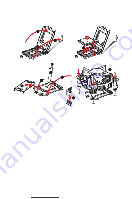
Please install the CPU into the CPU socket as shown below.


Important


Always unplug the power cord from the power outlet before installing or removing 

the CPU.


Please retain the CPU protective cap after installing the processor. MSI will deal 

with Return Merchandise Authorization (RMA) requests if only the motherboard 

comes with the protective cap on the CPU socket.


When installing a CPU, always remember to install a CPU heatsink. A CPU heatsink 

is necessary to prevent overheating and maintain system stability.


Confirm that the CPU heatsink has formed a tight seal with the CPU before booting 

your system.


Overheating can seriously damage the CPU and motherboard. Always make sure 

the cooling fans work properly to protect the CPU from overheating. Be sure to apply 

an even layer of thermal paste (or thermal tape) between the CPU and the heatsink to 

enhance heat dissipation.


Whenever the CPU is not installed, always protect the CPU socket pins by covering 

the socket with the plastic cap.


If you purchased a separate CPU and heatsink/ cooler, Please refer to the docu-

mentation in the heatsink/ cooler package for more details about installation.

1

4

6

5

7

8

9

3

2

Downloaded from 

ManualsNet.com

 search engine

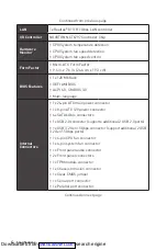
Summary of Contents for H310M PRO-C

Page 1: ...CPU_FAN1 SYS_FAN1 Fan Connectors 14 JTPM1 TPM Module Connector 14 JLPT1 Parallel Port Connector 15 JCOM1 Serial Port Connector 15 EZ Debug LED 15 JBAT1 Clear CMOS Reset BIOS Jumper 16 JCI1 Chassis Int...

Page 2: ...llation is completed This could cause permanent damage to the components as well as injury to the user If you need help during any installation step please consult a certified computer technician Alwa...

Page 3: ...t Onboard Graphics 1x VGA port supports resolution of 2048x1536 50Hz 2048x1280 60Hz 1x DVI D port supporting a maximumresolution of 1920x1200 60Hz 1x HDMI 1 4 port supports a maximum resolution of 409...

Page 4: ...0 Multi language Internal Connectors 1x 24 pin ATX main power connector 1x 8 pin ATX 12V power connector 4x SATA 6Gb s connectors 1x USB 2 0 connector supports additional 2 USB 2 0 ports 1x USB 3 2 G...

Page 5: ...ports 3x audio jacks Software Drivers DRAGON CENTER CPU Z MSI GAMING Intel Extreme Tuning Utility Google Chrome Google Toolbar Google Drive Norton Internet Security Solution Dragon Center Features Use...

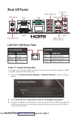
Page 6: ...A DVI D VGA Audio 7 1 channel Configuration To configure 7 1 channel audio you have to connect front audio I O module to JAUD1 connector and follow the below steps 1 Click on the Realtek HD Audio Man...

Page 7: ...PCI1 PCI_E1 CPU_FAN1 DIMMA1 DIMMB1 SATA2 M2_1 JCI1 JFP2 JFP1 SATA4 JAUD1 ATX_PWR1 CPU_PWR1 JUSB2 JUSB1 JLPT1 JTPM1 JCOM1 Overview of Components 48 29mm Distance from the center of the CPU to the neare...

Page 8: ...maintain system stability Confirm that the CPU heatsink has formed a tight seal with the CPU before booting your system Overheating can seriously damage the CPU and motherboard Always make sure the c...

Page 9: ...locking due to the memory frequency operates dependent on its Serial Presence Detect SPD Go to BIOS and find the DRAM Frequency to set the memory frequency if you want to operate the memory at the mar...

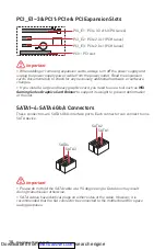
Page 10: ...upport its weight to prevent deformation of the slot BAT1 PCI_E1 PCIe 3 0 x16 CPU lanes PCI1 PCI slot PCI_E2 PCIe 2 0 x1 PCH lanes PCI_E3 PCIe 2 0 x1 PCH lanes SATA1 4 SATA 6Gb s Connectors These conn...

Page 11: ...h 7 Reset Switch 8 Power Switch 9 Reserved 10 No Pin JFP2 1 Speaker Buzzer 1 Speaker 2 Buzzer 3 Buzzer 4 Speaker HDD LED RESET SW HDD LED HDD LED HDD LED POWER LED POWER LED POWER LED J F P 1 JAUD1 Fr...

Page 12: ...per ATX power supply to ensure stable operation of the motherboard 24 13 1 12 ATX_PWR1 1 3 3V 13 3 3V 2 3 3V 14 12V 3 Ground 15 Ground 4 5V 16 PS ON 5 Ground 17 Ground 6 5V 18 Ground 7 Ground 19 Groun...

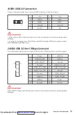
Page 13: ...19 Power 10 Ground 20 No Pin Important Note that the Power and Ground pins must be connected correctly to avoid possible damage JUSB1 USB 2 0 Connectors These connectors allow you to connect USB 2 0...

Page 14: ...ition 1 Ground 2 12V 3 Sense 4 Speed Control Signal Connector Default fan mode Max current Max power CPU_FAN1 PWM mode 2A 24W SYS_FAN1 PWM mode 2A 24W JTPM1 TPM Module Connector This connector is for...

Page 15: ...PINIT 7 PRND2 8 LPT_SLIN 9 PRND3 10 Ground 11 PRND4 12 Ground 13 PRND5 14 Ground 15 PRND6 16 Ground 17 PRND7 18 Ground 19 ACK 20 Ground 21 BUSY 22 Ground 23 PE 24 Ground 25 SLCT 26 No Pin JLPT1 Parall...

Page 16: ...computer is turned on Resetting the chassis intrusion warning 1 Go to BIOS SETTINGS Security Chassis Intrusion Configuration 2 Set Chassis Intrusion to Reset 3 Press F10 to save and exit and then pres...

Page 17: ...than 2 TB Supports more than 4 primary partitions with a GUID Partition Table GPT Supports unlimited number of partitions Supports full capabilities of new devices new devices may not provide backward...

Page 18: ...cessor Entering BIOS Setup Press Delete key when the Press DEL key to enter Setup Menu F11 to enter Boot Menu message appears on the screen during the boot process Function key F1 General Help F2 Add...

Page 19: ...om MSI website And then save the BIOS file into the USB flash drive Updating BIOS 1 Insert the USB flash drive that contains the update file into the USB port 2 Please refer the following methods to e...

Page 20: ...elect Run DVDSetup exe to open the installer If you turn off the AutoPlay feature from the Windows Control Panel you can still manually execute the DVDSetup exe from the root path of the MSI Driver Di...

Page 21: ...11 JAUD1 11 ATX_PWR1 CPU_PWR1 12 JUSB1 USB 2 0 13 JUSB2 USB 3 2 Gen 1 5Gbps 13 CPU_FAN1 SYS_FAN1 14 JTPM1 TPM 14 JLPT1 15 JCOM1 15 EZ LED 15 JBAT1 CMOS Reset BIOS 16 JCI1 16 UEFI BIOS 17 BIOS 18 BIOS...

Page 22: ...2 ESD ESD ESD PSU PSU 60 C 140 F Downloaded from ManualsNet com search engine...

Page 23: ...1 PCIe 2 0 x1 2 PCI 1 VGA 1 2048x1536 50Hz 2048x1280 60Hz DVI D 1 1920x1200 60Hz HDMI 1 4 1 4096x2160 30Hz H310 SATA 6Gb s 4 M 2 1 Key M PCIe 2 0 x2 SATA 6Gb s 2242 2260 2280 USB H310 USB 3 2 Gen 1 5...

Page 24: ...ro ATX 9 6 in x 7 6 in 24 4 cm x 19 3 cm BIOS 128 Mb 1 UEFI AMI BIOS ACPI 6 0 SM BIOS 3 0 24 ATX 1 8 ATX 12V 1 SATA 6Gb s 4 USB 2 0 1 USB 2 0 2 USB 3 2 Gen 1 5Gbps 1 USB 3 2 Gen 1 5Gbps 2 4 CPU 1 4 1...

Page 25: ...2 1 PS 2 1 VGA 1 DVI D 1 COM 1 HDMI 1 USB 2 0 A 4 LAN RJ45 1 USB 3 2 Gen1 5Gbps A 2 3 CPU Z MSI True Color DPC http download msi com manual mb DRAGONCENTER2 pdf Downloaded from ManualsNet com search e...

Page 26: ...SB 3 2 Gen 1 5Gbps A DVI D VGA 7 1 7 1 I O JAUD1 1 Realtek HD Audio Manager Advanced Settings 2 Mute the rear output device when a front headphone plugged in 3 I O LED LAN LAN LAN LED 10 Mbps 100 Mbps...

Page 27: ...PU PCI_E2 JBAT1 PCI_E3 PCI1 PCI_E1 CPU_FAN1 DIMMA1 DIMMB1 SATA2 M2_1 JCI1 JFP2 JFP1 SATA4 JAUD1 ATX_PWR1 CPU_PWR1 JUSB2 JUSB1 JLPT1 JTPM1 JCOM1 48 29mm CPU DIMM SATA1 SATA3 Downloaded from ManualsNet...

Page 28: ...8 CPU CPU CPU CPU CPU CPU MSI RMA CPU CPU CPU CPU CPU CPU CPU CPU CPU CPU 1 4 6 5 7 8 9 3 2 Downloaded from ManualsNet com search engine...

Page 29: ...9 DIMM DIMM 1 1 2 3 3 2 DIMMA1 Serial Presence Detect SPD BIOS DRAM Frequency DIMM www msi com M2_1 M 2 Key M M 2 M 2 1 3 M 2 30 30 2 Downloaded from ManualsNet com search engine...

Page 30: ...1 PCIe PCI MSI BAT1 PCI_E1 PCIe 3 0 x16 CPU PCI1 PCI PCI_E2 PCIe 2 0 x1 PCH PCI_E3 PCIe 2 0 x1 PCH SATA1 4 SATA 6Gb s SATA 6Gb s SATA SATA1 SATA2 SATA3 SATA4 SATA 90 SATA Downloaded from ManualsNet co...

Page 31: ...itch 9 Reserved 10 No Pin JFP2 1 Speaker Buzzer 1 Speaker 2 Buzzer 3 Buzzer 4 Speaker HDD LED RESET SW HDD LED HDD LED HDD LED POWER LED POWER LED POWER LED J F P 1 JAUD1 1 2 10 9 1 MIC L 2 Ground 3 M...

Page 32: ...Ground 15 Ground 4 5V 16 PS ON 5 Ground 17 Ground 6 5V 18 Ground 7 Ground 19 Ground 8 PWR OK 20 Res 9 5VSB 21 5V 10 12V 22 5V 11 12V 23 5V 12 3 3V 24 Ground 5 4 1 8 CPU_PWR1 1 Ground 5 12V 2 Ground 6...

Page 33: ...14 USB3_TX_C_DP 5 USB3_TX_C_DN 15 USB3_TX_C_DN 6 USB3_TX_C_DP 16 Ground 7 Ground 17 USB3_RX_DP 8 USB2 0 18 USB3_RX_DN 9 USB2 0 19 Power 10 Ground 20 No Pin JUSB1 USB 2 0 USB 2 0 VCC USB iPad iPhone iP...

Page 34: ...SYS_FAN1 PWM 2A 24W JTPM1 TPM TPM Trusted Platform Module TPM 1 2 14 13 1 LPC Clock 2 3V Standby power 3 LPC Reset 4 3 3V Power 5 LPC address data pin0 6 Serial IRQ 7 LPC address data pin1 8 5V Power...

Page 35: ...8 LPT_SLIN 9 PRND3 10 Ground 11 PRND4 12 Ground 13 PRND5 14 Ground 15 PRND6 16 Ground 17 PRND7 18 Ground 19 ACK 20 Ground 21 BUSY 22 Ground 23 PE 24 Ground 25 SLCT 26 No Pin JLPT1 JCOM1 1 2 10 9 1 DCD...

Page 36: ...ation 4 Chassis Intrusion Enabled 5 F10 Enter Yes 6 1 BIOS SETTINGS Security Chassis Intrusion Configuration 2 Chassis Intrusion Reset 3 F10 Enter Yes JBAT1 CMOS Reset BIOS CMOS CMOS CMOS BIOS BIOS 1...

Page 37: ...BIOS UEFI BIOS UEFI UEFI BIOS POST CSM 2TB GUID GPT 4 UEFI UEFI 32 Windows 64 Windows 10 GOP Graphics Output protocol GOP UEFI BIOS BIOS BIOS UEFI CSM CPU Temperature Motherboard Temperature VCore DD...

Page 38: ...18 UEFI BIOS BIOS BIOS BIOS BIOS BIOS HELP BIOS BIOS DEL F11 Delete F1 F2 F3 F4 CPU F5 Memory Z Z F6 F7 EZ F8 F9 F10 F12 USB FAT FAT32 Ctrl F F10 Yes No Downloaded from ManualsNet com search engine...

Page 39: ...BIOS BIOS BIOS BIOS BIOS F6 CMOS BIOS CMOS BIOS M FLASH BIOS BIOS MSI BIOS USB BIOS 1 USB 2 POST Ctrl F5 Yes BIOS POST Del M FLASH Yes 3 BIOS BIOS 4 Yes BIOS 5 100 Downloaded from ManualsNet com searc...

Page 40: ...1 5 Windows 10 USB 6 Press any key to boot from CD or DVD 7 Windows 10 1 Windows 10 2 MSI 3 Select to choose what happens with this disc Run DVDSetup exe MSI DVDSetup exe 4 Drivers Software 5 Install...

Page 41: ...S_FAN1 Connecteurs pour ventilateurs 14 JTPM1 Connecteur de module TPM 14 JLPT1 Connecteur de port parall le 15 JCOM1 Connecteur de port s rie 15 EZ Debug LED 15 JBAT1 Cavalier Clear CMOS R initialise...

Page 42: ...rte m re ou ailleurs dans le bo tier de l ordinateur Ne d marrez pas l ordinateur avant d avoir termin l installation Ceci peut endommager les composants ou vous blesser Si vous avez besoin d aide pen...

Page 43: ...s 1 x port VGA supportant une r solution maximum de 2048x1536 50Hz 2048x1280 60Hz 1 x port DVI D supportant une r solution maximum de 1920x1200 60Hz 1 x port HDMI 1 4 supportant une r solution maximum...

Page 44: ...ecteurs internes 1 x connecteur d alimentation principal ATX 24 broches 1 x connecteur d alimentation ATX 12V 8 broches 4 x connecteurs SATA 6Gb s 1 x connecteur USB 2 0 support de 2 autres ports USB...

Page 45: ...en1 5Gb s Type A 3 x jacks audio Logiciel Pilotes DRAGON CENTER CPU Z MSI GAMING Intel Extreme Tuning Utility Google Chrome Google Toolbar Google Drive Norton Internet Security Solution Fonctions Drag...

Page 46: ...anal Pour r gler le syst me audio 7 1 connectez le module audio entr e sortie du panneau avant au connecteur JAUD1 et suivez les tapes ci dessous 1 Cliquez sur Realtek HD Audio Manager Advanced Settin...

Page 47: ...E3 PCI1 PCI_E1 CPU_FAN1 DIMMA1 DIMMB1 SATA2 M2_1 JCI1 JFP2 JFP1 SATA4 JAUD1 ATX_PWR1 CPU_PWR1 JUSB2 JUSB1 JLPT1 JTPM1 JCOM1 Vue d ensemble des composants 48 29mm Distance entre le centre du CPU et le...

Page 48: ...t maintenir la stabilit du syst me Assurez vous de l tanch it entre le ventilateur et le processeur avant de d mar rer votre syst me La surchauffe peut facilement endommager le processeur et la carte...

Page 49: ...fr quence d op ration de m moire d pend du Serial Presence Detect SPD Rendez vous sur le BIOS et choisissez la fonction DRAM Frequency pour r gler la fr quence de m moire si vous voulez faire fonctio...

Page 50: ...r supporter son poids et pour viter la d formation du slot BAT1 PCI_E1 PCIe 3 0 x16 voies CPU PCI1 slot PCI PCI_E2 PCIe 2 0 x1 voies PCH PCI_E3 PCIe 2 0 x1 voies PCH SATA1 4 Connecteurs SATA 6Gb s Ces...

Page 51: ...tch 6 Power Switch 7 Reset Switch 8 Power Switch 9 Reserved 10 No Pin JFP2 1 Speaker Buzzer 1 Speaker 2 Buzzer 3 Buzzer 4 Speaker HDD LED RESET SW HDD LED HDD LED HDD LED POWER LED POWER LED POWER LED...

Page 52: ...ranch s aux connecteurs ad quats afin garantir une op ration stable de la carte m re 24 13 1 12 ATX_PWR1 1 3 3V 13 3 3V 2 3 3V 14 12V 3 Ground 15 Ground 4 5V 16 PS ON 5 Ground 17 Ground 6 5V 18 Ground...

Page 53: ...rtant Notez que les c bles d alimentation et de terre doivent tre branch s correctement afin d viter d endommager la carte JUSB1 Connecteur USB 2 0 Ce connecteur vous permet de relier des ports USB 2...

Page 54: ...OS Hardware Monitor 1 D finition des broches en mode PWM 1 Ground 2 12V 3 Sense 4 Speed Control Signal Connecteur Mode ventilateur par d faut Courant Max Alimentation Max CPU_FAN1 mode PWM 2A 24W SYS_...

Page 55: ...tect ou que son initialisation a chou 1 2 26 25 1 RSTB 2 AFD 3 PRND0 4 ERR 5 PRND1 6 PINIT 7 PRND2 8 LPT_SLIN 9 PRND3 10 Ground 11 PRND4 12 Ground 13 PRND5 14 Ground 15 PRND6 16 Ground 17 PRND7 18 Gr...

Page 56: ...BIOS SETTINGS R glages Security S curit Chassis Intrusion Configuration Configuration intrusion ch ssis 2 Mettez Chassis Intrusion Intrusion ch ssis en Reset Remettre 3 Appuyez sur F10 pour sauvegarde...

Page 57: ...des partitions de disque dur sup rieures 2 To Prend en charge plus de 4 partitions principales avec une table de partition GUID GPT Prend en charge un nombre illimit de partitions Prend en charge tout...

Page 58: ...etup du BIOS Pendant le d marrage lorsqu appara t le message Press DEL key to enter Setup Menu F11 to enter Boot Menu sur l cran veuillez appuyer sur la touche Suppr Touches de fonction F1 Aide g n ra...

Page 59: ...votre carte m re sur le site MSI Ensuite veuillez sauvegarder le nouveau BIOS sur la cl USB Mettre le BIOS jour 1 Connectez la cl USB contenant le profil au port USB 2 Veuillez vous r f rer aux m tho...

Page 60: ...sc puis choisissez Lancer DVDSetup exe Run DVDSetup exe pour ouvrir l outil d installation Si vous d sactivez la fonction AutoPlay dans le panneau de configuration Windows vous pouvez quand m me ex cu...

Page 61: ...schl sse f r L fter 14 JTPM1 TPM Anschluss 14 JLPT1 Parallele Schnittstelle 15 JCOM1 Serieller Anschluss 15 EZ Debug LED 15 JBAT1 Clear CMOS Steckbr cke Reset BIOS 16 JCI1 Geh usekontaktanschluss 16 U...

Page 62: ...nstallation abgeschlossen ist Dies k nnte permanente Sch den an den Komponenten sowie zu das Verletzung des Benutzers verursachen Sollten Sie Hilfe bei der Installation ben tigen wenden Sie sich bitte...

Page 63: ...rafik 1x VGA Anschluss Unterst tzung einer maximalen Aufl sung von 2048x1536 50Hz 2048x1280 60Hz 1x DVI D Anschluss Unterst tzung einer maximalen Aufl sung von 1920x1200 60Hz 1x HDMI 1 4 Anschluss Unt...

Page 64: ...IOS 3 0 Mehrsprachenunterst tzung Interne Anschl sse 1x 24 poliger ATX Stromanschluss 1x 8 poliger ATX 12V Stromanschluss 4x SATA 6Gb s Anschl sse 1x USB 2 0 Anschluss unterst tzt zus tzliche 2 USB 2...

Page 65: ...GBit s Typ A Anschl sse 3x Audiobuchsen Software Treiber DRAGON CENTER CPU Z MSI GAMING Intel Extreme Tuning Utility Google Chrome Google Toolbar Google Drive Norton Internet Security Solution Dragon...

Page 66: ...Audio zu konfigurieren m ssen Sie den Front Audio Anschluss mit dem JAUD1 Anschluss verbinden und folgen Sie die untenstehenden Schritten 1 Klicken Sie auf Realtek HD Audio Manager Advanced Settings u...

Page 67: ...1 PCI_E1 CPU_FAN1 DIMMA1 DIMMB1 SATA2 M2_1 JCI1 JFP2 JFP1 SATA4 JAUD1 ATX_PWR1 CPU_PWR1 JUSB2 JUSB1 JLPT1 JTPM1 JCOM1 bersicht der Komponenten 48 29mm Abstand zwischen der Mitte der CPU und dem n chst...

Page 68: ...t beizubehalten Stellen Sie sicher dass Ihr K hlk rper eine feste Verbindung mit der CPU herg estellt hat bevor Sie Ihr System starten berhitzung besch digt die CPU und das System nachhaltig Stellen S...

Page 69: ...rigeren Frequenz arbeiten als der festgelegte Wert abh ngig von dem SPD Serial Presence Detect Stellen Sie im BIOS Setup mit DRAM Frequency die Speicherfrequenz ein wenn Sie mit der festgelegten oder...

Page 70: ...abilisator Graphics Card Bolster der das Gewicht tr gt und eine Verformung des Steckplatzes vermeidet BAT1 PCI_E1 PCIe 3 0 x16 CPU Lanes PCI1 PCI Steckplatz PCI_E2 PCIe 2 0 x1 PCH Lanes PCI_E3 PCIe 2...

Page 71: ...et Switch 8 Power Switch 9 Reserved 10 No Pin JFP2 1 Speaker Buzzer 1 Speaker 2 Buzzer 3 Buzzer 4 Speaker HDD LED RESET SW HDD LED HDD LED HDD LED POWER LED POWER LED POWER LED J F P 1 JAUD1 Audioansc...

Page 72: ...ils verbunden sind um einen stabilen Betrieb der Hauptplatine sicherzustellen 24 13 1 12 ATX_PWR1 1 3 3V 13 3 3V 2 3 3V 14 12V 3 Ground 15 Ground 4 5V 16 PS ON 5 Ground 17 Ground 6 5V 18 Ground 7 Grou...

Page 73: ...Stromf hrende Leitung und Erdleitung bezeichneten Pins korrekt verbinden m ssen ansonsten kann es zu Sch den kommen JUSB1 USB 2 0 Anschluss Mit diesem Anschluss k nnen Sie die USB 2 0 Anschl sse auf...

Page 74: ...WM Modus 1 Ground 2 12V 3 Sense 4 Speed Control Signal Anschluss Standard l ftermodus Max Strom Max Leistung CPU_FAN1 PWM Modus 2A 24W SYS_FAN1 PWM Modus 2A 24W JTPM1 TPM Anschluss Dieser Anschluss wi...

Page 75: ...LPT_SLIN 9 PRND3 10 Ground 11 PRND4 12 Ground 13 PRND5 14 Ground 15 PRND6 16 Ground 17 PRND7 18 Ground 19 ACK 20 Ground 21 BUSY 22 Ground 23 PE 24 Ground 25 SLCT 26 No Pin JLPT1 Parallele Schnittstell...

Page 76: ...S Security Chassis Intrusion Configuration 2 Stellen Sie Chassis Intrusion auf Reset 3 Dr cken Sie F10 zum Speichern und Beenden und dr cken Sie dann die Enter Taste um Ja auszuw hlen JBAT1 Clear CMOS...

Page 77: ...terst tzt mehr als 4 prim re Partitionen mit einer GUID Partitionstabelle GPT Unterst tzt eine unbegrenzte Anzahl an Partitionen Unterst tzt den vollen Funktionsumfang neuer Ger te neue Ger te bieten...

Page 78: ...end des BOOT Vorgangs dr cken Sie die Taste ENTF wenn die Meldung Press DEL key to enter Setup Menu F11 to enter Boot Menu erscheint Funktionstasten F1 Allgemeine Hilfe F2 Hinzuf gen Entfernen eines F...

Page 79: ...Datei auf USB Flash Laufwerk BIOS Aktualisierungsschritte 1 Schlie en das USB Flashlaufwerk mit der BIOS Datei an den Computer 2 Bitte folgen Sie den nachfolgenden Schritten um in den Blitz Modus zu s...

Page 80: ...hlen Sie DVDSetup exe starten aus um den Installer zu ffnen Wenn Sie die AutoPlay Funktionen in der Windows Systemsteuerung ausschalten k nnen Sie das Programm DVD Setup exe im Hauptverzeichnis der M...

Page 81: ...11 JAUD1 11 ATX_PWR1 CPU_PWR1 12 JUSB1 USB 2 0 13 JUSB2 USB 3 2 Gen 1 5 13 CPU_FAN1 SYS_FAN1 14 JTPM1 14 JLPT1 15 JCOM1 15 EZ 15 JBAT1 CMOS BIOS 16 JCI1 16 UEFI BIOS 17 BIOS 18 BIOS 18 BIOS 19 BIOS 1...

Page 82: ...2 60 C 140 F Downloaded from ManualsNet com search engine...

Page 83: ...3 0 x16 2x PCIe 2 0 x1 1x PCI 1x VGA 2048x1536 50 2048x1280 60 1x DVI D 1920x1200 60 1x HDMI 1 4 4096x2160 30 Intel H310 4x SATA 6 1x M 2 M PCIe 2 0 x2 SATA 6 2242 2260 2280 USB Intel H310 4x USB 3 2...

Page 84: ...ATX 9 6 x 7 6 24 4 x 19 3 BIOS 1x 128 UEFI AMI BIOS ACPI 6 0 SM BIOS 3 0 1x 24 ATX 1x 8 ATX 12 4x SATA 6 1x USB 2 0 2 USB 2 0 1x USB 3 2 Gen1 5 2 USB 3 2 Gen1 5 1x 4 1x 4 1x 2x 1x TPM 1x 1x CMOS 1x 1x...

Page 85: ...I GAMING Intel Extreme Tuning Utility Google Chrome Google Toolbar Google Drive Norton Internet Security Solution Dragon Center User Scenario Hardware Monitor True Color Live Update DPC Latency Tuner...

Page 86: ...AN 1 USB 2 0 Type A COM USB 3 2 Gen 1 5 Type A DVI D VGA Audio 7 1 7 1 JAUD1 1 Realtek HD Audio Manager Advanced Settings 2 Mute the rear output device when a front headphone plugged in 3 Downloaded f...

Page 87: ...AN1 PCI_E2 JBAT1 PCI_E3 PCI1 PCI_E1 CPU_FAN1 DIMMA1 DIMMB1 SATA2 M2_1 JCI1 JFP2 JFP1 SATA4 JAUD1 ATX_PWR1 CPU_PWR1 JUSB2 JUSB1 JLPT1 JTPM1 JCOM1 48 29 DIMM SATA1 SATA3 Downloaded from ManualsNet com s...

Page 88: ...8 MSI 1 4 6 5 7 8 9 3 2 Downloaded from ManualsNet com search engine...

Page 89: ...9 DIMM DIMM 1 1 2 3 3 2 DIMMA1 SPD Serial Presence Detect BIOS DRAM Frequency www msi com M2_1 M 2 M M 2 M 2 1 3 M 2 30 30 2 Downloaded from ManualsNet com search engine...

Page 90: ...I Gaming Series Graphics Card Bolster BAT1 PCI_E1 PCIe 3 0 x16 CPU PCI1 PCI PCI_E2 PCIe 2 0 x1 PCH PCI_E3 PCIe 2 0 x1 PCH SATA1 4 SATA 6 SATA 6 SATA SATA1 SATA2 SATA3 SATA4 SATA SATA Downloaded from M...

Page 91: ...tch 8 Power Switch 9 Reserved 10 No Pin JFP2 1 Speaker Buzzer 1 Speaker 2 Buzzer 3 Buzzer 4 Speaker HDD LED RESET SW HDD LED HDD LED HDD LED POWER LED POWER LED POWER LED J F P 1 JAUD1 1 2 10 9 1 MIC...

Page 92: ...round 15 Ground 4 5V 16 PS ON 5 Ground 17 Ground 6 5V 18 Ground 7 Ground 19 Ground 8 PWR OK 20 Res 9 5VSB 21 5V 10 12V 22 5V 11 12V 23 5V 12 3 3V 24 Ground 5 4 1 8 CPU_PWR1 1 Ground 5 12V 2 Ground 6 1...

Page 93: ...C_DP 5 USB3_TX_C_DN 15 USB3_TX_C_DN 6 USB3_TX_C_DP 16 Ground 7 Ground 17 USB3_RX_DP 8 USB2 0 18 USB3_RX_DN 9 USB2 0 19 Power 10 Ground 20 No Pin JUSB1 USB 2 0 USB 2 0 VCC iPad iPhone iPod USB MSI DRAG...

Page 94: ...2 24 SYS_FAN1 PWM 2 24 JTPM1 Trusted Platform Module 1 2 14 13 1 LPC Clock 2 3V Standby power 3 LPC Reset 4 3 3V Power 5 LPC address data pin0 6 Serial IRQ 7 LPC address data pin1 8 5V Power 9 LPC ad...

Page 95: ...IN 9 PRND3 10 Ground 11 PRND4 12 Ground 13 PRND5 14 Ground 15 PRND6 16 Ground 17 PRND7 18 Ground 19 ACK 20 Ground 21 BUSY 22 Ground 23 PE 24 Ground 25 SLCT 26 No Pin JLPT1 JCOM1 1 2 10 9 1 DCD 2 SIN 3...

Page 96: ...nfiguration 4 Chassis Intrusion Enabled 5 F10 Enter Yes 6 1 BIOS SETTINGS Security Chassis Intrusion Configuration 2 Chassis Intrusion Reset 3 F10 Enter Yes JBAT1 CMOS BIOS CMOS CMOS BIOS BIOS 1 2 JBA...

Page 97: ...UEFI BIOS CSM UEFI BIOS UEFI BIOS UEFI UEFI BIOS CSM POST 2 4 GUID GPT UEFI UEFI 32 Windows 64 Windows 10 There is no GOP Graphics Output protocol support detected in this graphics card GOP UEFI BIOS...

Page 98: ...OS BIOS BIOS BIOS HELP BIOS BIOS Delete Press DEL key to enter Setup Menu F11 to enter Boot Menu F1 F2 F3 F4 F5 Memory Z F6 F7 EZ F8 F9 F10 F12 USB FAT FAT32 Ctrl F F10 Yes No Downloaded from ManualsN...

Page 99: ...I BIOS BIOS BIOS BIOS F6 CMOS BIOS CMOS BIOS BIOS M FLASH BIOS MSI BIOS USB BIOS 1 USB USB 2 Ctrl F5 POST Yes Del POST BIOS M FLASH Yes 3 BIOS BIOS 4 Yes BIOS 5 Downloaded from ManualsNet com search e...

Page 100: ...B 6 Press any key to boot from CD or DVD 7 Windows 10 1 Windows 10 2 MSI Driver Disc 3 Select to choose what happens with this disc Run DVDSetup exe Windows DVDSetup exe MSI Driver Disc 4 Drivers Soft...

Page 101: ...JFP2 11 JAUD1 11 ATX_PWR1 CPU_PWR1 12 JUSB1 USB 2 0 13 JUSB2 USB 3 2 Gen 1 5Gbps 13 CPU_FAN1 SYS_FAN1 14 JTPM1 TPM 14 JLPT1 15 JCOM1 15 LED 15 JBAT1 CMOS BIOS 16 JCI1 16 UEFI BIOS 17 BIOS 18 BIOS 18 B...

Page 102: ...2 ESD ESD ESD 60 140 Downloaded from ManualsNet com search engine...

Page 103: ...16 2 PCIe 2 0 x1 1 PCI 1 VGA 2048x1536 50Hz 2048x1280 60Hz 1 DVI D 1920x1200 60Hz 1 HDMI 1 4 4096x2160 30Hz Intel H310 4 SATA 6Gb s 1 M 2 M PCIe 2 0 x2 SATA 6Gb s 2242 2260 2280 USB Intel H310 4 USB 3...

Page 104: ...9 6 x 7 6 24 4 x 19 3 BIOS 1 128 Mb flash UEFI AMI BIOS ACPI 6 0 SM BIOS 3 0 1 24 pin ATX 1 8 pin ATX 12V 4 SATA 6Gb s 1 USB 2 0 2 USB 2 0 1 USB 3 2 Gen 1 5Gbps 2 USB 3 2 Gen 1 5Gbps 1 4 pin CPU 1 4 p...

Page 105: ...USB 2 0 Type A 1 LAN RJ45 2 USB 3 2 Gen1 5Gbps Type A 3 DRAGON CENTER MSI GAMING CPU Z Google Google Google Dragon Center True Color Live Update DPC http download msi com manual mb DRAGONCENTER2 pdf...

Page 106: ...S 2 PS 2 1Gbps LAN USB 2 0 Type A COM USB 3 2 Gen 1 5Gbps Type A DVI D VGA 7 1 7 1 I O JAUD1 1 Realtek HD Audio Manager Advanced Settings 2 Mute the rear output device when a front headphone plugged i...

Page 107: ...CPU PCI_E2 JBAT1 PCI_E3 PCI1 PCI_E1 CPU_FAN1 DIMMA1 DIMMB1 SATA2 M2_1 JCI1 JFP2 JFP1 SATA4 JAUD1 ATX_PWR1 CPU_PWR1 JUSB2 JUSB1 JLPT1 JTPM1 JCOM1 48 29 CPU DIMM SATA1 SATA3 Downloaded from ManualsNet c...

Page 108: ...8 CPU CPU CPU CPU CPU RMA CPU CPU CPU CPU CPU CPU CPU CPU CPU CPU CPU CPU 1 4 6 5 7 8 9 3 2 Downloaded from ManualsNet com search engine...

Page 109: ...9 DIMM DIMM 1 1 2 3 3 2 DIMMA1 SPD BIOS DRAM Frequency DIMM www msi com M2_1 M 2 M M 2 M 2 1 3 M 2 30 30 2 Downloaded from ManualsNet com search engine...

Page 110: ...1 PCIe PCI MSI BAT1 PCI_E1 PCIe 3 0 x16 CPU PCI1 PCI PCI_E2 PCIe 2 0 x1 PCH PCI_E3 PCIe 2 0 x1 PCH SATA1 4 SATA 6Gb s SATA 6Gb s SATA SATA1 SATA2 SATA3 SATA4 SATA 90 SATA Downloaded from ManualsNet co...

Page 111: ...witch 8 Power Switch 9 Reserved 10 No Pin JFP2 1 Speaker Buzzer 1 Speaker 2 Buzzer 3 Buzzer 4 Speaker HDD LED RESET SW HDD LED HDD LED HDD LED POWER LED POWER LED POWER LED J F P 1 JAUD1 1 2 10 9 1 MI...

Page 112: ...Ground 15 Ground 4 5V 16 PS ON 5 Ground 17 Ground 6 5V 18 Ground 7 Ground 19 Ground 8 PWR OK 20 Res 9 5VSB 21 5V 10 12V 22 5V 11 12V 23 5V 12 3 3V 24 Ground 5 4 1 8 CPU_PWR1 1 Ground 5 12V 2 Ground 6...

Page 113: ..._TX_C_DP 5 USB3_TX_C_DN 15 USB3_TX_C_DN 6 USB3_TX_C_DP 16 Ground 7 Ground 17 USB3_RX_DP 8 USB2 0 18 USB3_RX_DN 9 USB2 0 19 Power 10 Ground 20 No Pin JUSB1 USB 2 0 USB 2 0 VCC iPad iPhone iPod USB MSI...

Page 114: ...PWM 2A 24W SYS_FAN1 PWM 2A 24W JTPM1 TPM TPM TPM 1 2 14 13 1 LPC Clock 2 3V Standby power 3 LPC Reset 4 3 3V Power 5 LPC address data pin0 6 Serial IRQ 7 LPC address data pin1 8 5V Power 9 LPC addres...

Page 115: ...LPT_SLIN 9 PRND3 10 Ground 11 PRND4 12 Ground 13 PRND5 14 Ground 15 PRND6 16 Ground 17 PRND7 18 Ground 19 ACK 20 Ground 21 BUSY 22 Ground 23 PE 24 Ground 25 SLCT 26 No Pin JLPT1 JCOM1 1 2 10 9 1 DCD 2...

Page 116: ...guration 4 Chassis Intrusion Enabled 5 F10 Enter Yes 6 1 BIOS SETTINGS Security Chassis Intrusion Configuration 2 Chassis Intrusion Reset 3 F10 Enter Yes JBAT1 CMOS BIOS CMOS CMOS CMOS BIOS BIOS 1 2 J...

Page 117: ...UEFI UEFI 32 Windows 64 Windows 10 There is no GOP Graphics Output protocol support detected in this graphics card GOP Graphics Output protocol GOP UEFI BIOS BIOS BIOS UEFI CSM CPU Temperature Mother...

Page 118: ...S BIOS BIOS BIOS BIOS Press DEL key to enter Setup Menu F11 to enter Boot Menu Delete F1 F2 F3 Favorites F4 CPU F5 Memory Z F6 F7 EZ F8 F9 F10 F12 U FAT FAT32 Ctrl F F10 Yes No Downloaded from Manuals...

Page 119: ...S BIOS BIOS BIOS BIOS F6 CMOS CMOS BIOS BIOS M FLASH BIOS MSI BIOS BIOS U BIOS 1 U USB 2 flash POST Ctrl F5 Yes POST Del BIOS M FLASH Yes 3 BIOS BIOS 4 Yes BIOS 5 100 Downloaded from ManualsNet com se...

Page 120: ...Press any key to boot from CD or DVD 7 Windows 10 1 Windows 10 2 MSI 3 Select to choose what happens with this disc Run DVDSetup exe Windows AutoPlay MSI DVDSetup exe 4 Drivers Software 5 Install 6 7...

Page 121: ...11 JAUD1 11 ATX_PWR1 CPU_PWR1 12 JUSB1 USB 2 0 13 JUSB2 USB 3 2 Gen 1 5Gbps 13 CPU_FAN1 SYS_FAN1 14 JTPM1 TPM 14 JLPT1 15 JCOM1 15 LED 15 JBAT1 CMOS BIOS 16 JCI1 16 UEFI BIOS 17 BIOS 18 BIOS 18 BIOS 1...

Page 122: ...2 ESD 60 C 140 F Downloaded from ManualsNet com search engine...

Page 123: ...m 1 PCIe 3 0 x16 2 PCIe 2 0 x1 1 PCI 1 VGA 2048x1536 50Hz 2048x1280 60Hz 1 DVI D 1920x1200 60Hz 1 HDMI 1 4 4096x2160 30Hz Intel H310 4 SATA 6Gb s 1 M 2 M PCIe 2 0 x2 SATA 6Gb s 2242 2260 2280 USB Inte...

Page 124: ...9 6 x 7 6 24 4 x 19 3 BIOS 1 128 Mb flash UEFI AMI BIOS ACPI 6 0 SM BIOS 3 0 1 24 pin ATX 1 8 pin ATX 12V 4 SATA 6Gb s 1 USB 2 0 2 USB 2 0 1 USB 3 2 Gen1 5Gbps 2 USB 3 2 Gen1 5Gbps 1 4 pin CPU 1 4 pi...

Page 125: ...Z MSI GAMING Intel Extreme Tuning Utility Google Chrome Google Google Norton Internet Security Solution Dragon Center User Scenario Hardware Monitor True Color Live Update DPC Latency Tuner Speed Up S...

Page 126: ...10 Mbps 100 Mbps 1 Gbps LED PS 2 PS 2 1Gbps USB 2 0 Type A COM USB 3 2 Gen 1 5Gbps Type A DVI D VGA 7 1 7 1 I O JAUD1 1 Realtek HD Audio Manager Advanced Settings 2 3 I O Downloaded from ManualsNet co...

Page 127: ...PU PCI_E2 JBAT1 PCI_E3 PCI1 PCI_E1 CPU_FAN1 DIMMA1 DIMMB1 SATA2 M2_1 JCI1 JFP2 JFP1 SATA4 JAUD1 ATX_PWR1 CPU_PWR1 JUSB2 JUSB1 JLPT1 JTPM1 JCOM1 48 29mm CPU DIMM SATA1 SATA3 Downloaded from ManualsNet...

Page 128: ...8 CPU CPU CPU CPU CPU Return Merchandise Authorization RMA CPU CPU CPU CPU CPU CPU CPU CPU 1 4 6 5 7 8 9 3 2 Downloaded from ManualsNet com search engine...

Page 129: ...9 DIMM 1 1 2 3 3 2 DIMMA1 Serial Presence Detect SPD BIOS DRAM Frequency www msi com M2_1 M 2 M M 2 M 2 1 3 M 2 30 30 2 Downloaded from ManualsNet com search engine...

Page 130: ...PCI MSI Gaming Series BAT1 PCI_E1 PCIe 3 0 x16 CPU PCI1 PCI PCI_E2 PCIe 2 0 x1 PCH PCI_E3 PCIe 2 0 x1 PCH SATA1 4 SATA 6Gb s SATA 6Gb s SATA SATA1 SATA2 SATA3 SATA4 SATA 90 SATA Downloaded from Manual...

Page 131: ...witch 8 Power Switch 9 Reserved 10 No Pin JFP2 1 Speaker Buzzer 1 Speaker 2 Buzzer 3 Buzzer 4 Speaker HDD LED RESET SW HDD LED HDD LED HDD LED POWER LED POWER LED POWER LED J F P 1 JAUD1 1 2 10 9 1 MI...

Page 132: ...Ground 15 Ground 4 5V 16 PS ON 5 Ground 17 Ground 6 5V 18 Ground 7 Ground 19 Ground 8 PWR OK 20 Res 9 5VSB 21 5V 10 12V 22 5V 11 12V 23 5V 12 3 3V 24 Ground 5 4 1 8 CPU_PWR1 1 Ground 5 12V 2 Ground 6...

Page 133: ..._TX_C_DP 5 USB3_TX_C_DN 15 USB3_TX_C_DN 6 USB3_TX_C_DP 16 Ground 7 Ground 17 USB3_RX_DP 8 USB2 0 18 USB3_RX_DN 9 USB2 0 19 Power 10 Ground 20 No Pin JUSB1 USB 2 0 USB 2 0 VCC USB iPad iPhone iPod MSI...

Page 134: ...FAN1 PWM 2A 24W SYS_FAN1 PWM 2A 24W JTPM1 TPM TPM TPM 1 2 14 13 1 LPC Clock 2 3V Standby power 3 LPC Reset 4 3 3V Power 5 LPC address data pin0 6 Serial IRQ 7 LPC address data pin1 8 5V Power 9 LPC ad...

Page 135: ...SLIN 9 PRND3 10 Ground 11 PRND4 12 Ground 13 PRND5 14 Ground 15 PRND6 16 Ground 17 PRND7 18 Ground 19 ACK 20 Ground 21 BUSY 22 Ground 23 PE 24 Ground 25 SLCT 26 No Pin JLPT1 JCOM1 1 2 10 9 1 DCD 2 SIN...

Page 136: ...guration 4 Chassis Intrusion Enabled 5 F10 Enter Yes 6 1 BIOS SETTINGS Security Chassis Intrusion Configuration 2 Chassis Intrusion Reset 3 F10 Enter Yes JBAT1 CMOS BIOS CMOS CMOS CMOS BIOS BIOS 1 2 J...

Page 137: ...dows operating system 64 Windows 10 Older graphics card There is no GOP Graphics Output protocol support detected in this graphics card GOP Graphics Output protocol GOP UEFI BIOS BIOS BIOS UEFI CSM CP...

Page 138: ...18 UEFI BIOS BIOS T BIOS BIOS BIOS HELP BIOS BIOS DEL F11 Delete F1 F2 F3 F4 CPU F5 Memory Z F6 F7 EZ F8 F9 F10 F12 USB FAT FAT32 Ctrl F F10 Downloaded from ManualsNet com search engine...

Page 139: ...BIOS BIOS BIOS BIOS BIOS F6 CMOS CMOS CMOS BIOS BIOS M FLASH BIOS MSI BIOS BIOS USB BIOS 1 USB 2 POST Ctrl F5 POST Del BIOS M FLASH 3 BIOS BIOS 4 Yes BIOS 5 100 Downloaded from ManualsNet com search...

Page 140: ...ws 10 1 2 Windows 10 USB 3 4 POST F11 5 6 Press any key to boot from CD or DVD 7 Windows 10 1 Windows 10 2 MSI 3 DVDSetup exe Windows MSI DVDSetup exe 4 5 6 7 8 1 2 3 4 5 6 7 Downloaded from ManualsNe...

Page 141: ...11 JAUD1 11 ATX_PWR1 CPU_PWR1 12 JUSB1 USB 2 0 13 JUSB2 USB 3 2 Gen 1 5Gbps 13 CPU_FAN1 SYS_FAN1 14 JTPM1 TPM 14 JLPT1 15 JCOM1 15 EZ Debug LED 15 JBAT1 CMOS BIOS 16 JCI1 16 UEFI BIOS 17 BIOS 18 BIOS...

Page 142: ...2 ESD PC ESD ESD PC PC PC PC PC PC 60OC 140OF Downloaded from ManualsNet com search engine...

Page 143: ...PCIe 3 0 x16 x1 PCIe 2 0 x1 x2 PCI x1 VGA x1 2048x1536 50Hz 2048x1280 60Hz DVI D x1 1920x1200 60Hz HDMI 1 4 x1 4096x2160 30Hz Intel H310 SATA 6Gb s x4 M 2 x1 Key M PCIe 2 0 x2 SATA 6Gb s 2242 2260 22...

Page 144: ...9 6 in x 7 6 in 24 4 cm x 19 3 cm BIOS 128 Mb x1 UEFI AMI BIOS ACPI 6 0 SM BIOS 3 0 24 ATX x1 8 ATX 12V x1 SATA 6Gb s x4 USB 2 0 x1 2 USB 2 0 USB 3 2 Gen 1 5Gbps x1 2 USB 3 2 Gen1 5Gbps 4 CPU x1 4 x1...

Page 145: ...CPU Z MSI GAMING Intel Extreme Tuning Utility Google Chrome Google Toolbar Google Drive Norton Internet Security Solution User Scenario Hardware Monitor True Color Live Update DPC Latency Tuner Speed...

Page 146: ...AN LED PS 2 PS 2 1Gbps LAN USB 2 0 Type A COM USB 3 2 Gen 1 5Gbps Type A DVI D VGA 7 1 7 1 I O JAUD1 1 Realtek HD Audio Manager Advanced Settings 2 Mute the rear output device when a front headphone p...

Page 147: ...PU PCI_E2 JBAT1 PCI_E3 PCI1 PCI_E1 CPU_FAN1 DIMMA1 DIMMB1 SATA2 M2_1 JCI1 JFP2 JFP1 SATA4 JAUD1 ATX_PWR1 CPU_PWR1 JUSB2 JUSB1 JLPT1 JTPM1 JCOM1 48 29mm CPU DIMM SATA1 SATA3 Downloaded from ManualsNet...

Page 148: ...8 CPU CPU CPU CPU CPU CPU CPU CPU CPU CPU CPU CPU CPU CPU CPU CPU CPU CPU CPU CPU CPU CPU CPU CPU 1 4 6 5 7 8 9 3 2 Downloaded from ManualsNet com search engine...
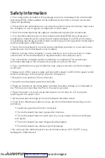
Page 149: ...9 DIMM DIMM 1 1 2 3 3 2 DIMMA1 SPD BIOS DRAM Frequency DIMM www msi com M2_1 M 2 Key M M 2 M 2 1 3 M 2 30 30 2 Downloaded from ManualsNet com search engine...
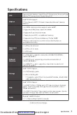
Page 150: ...ing Series Graphics Card Bolster BAT1 PCI_E1 PCIe 3 0 x16 CPU PCI1 PCI PCI_E2 PCIe 2 0 x1 PCH PCI_E3 PCIe 2 0 x1 PCH SATA1 4 SATA 6Gb s SATA 6Gb s SATA SATA1 SATA2 SATA3 SATA4 SATA 90 SATA Downloaded...

Page 151: ...witch 8 Power Switch 9 Reserved 10 No Pin JFP2 1 Speaker Buzzer 1 Speaker 2 Buzzer 3 Buzzer 4 Speaker HDD LED RESET SW HDD LED HDD LED HDD LED POWER LED POWER LED POWER LED J F P 1 JAUD1 1 2 10 9 1 MI...

Page 152: ...Ground 15 Ground 4 5V 16 PS ON 5 Ground 17 Ground 6 5V 18 Ground 7 Ground 19 Ground 8 PWR OK 20 Res 9 5VSB 21 5V 10 12V 22 5V 11 12V 23 5V 12 3 3V 24 Ground 5 4 1 8 CPU_PWR1 1 Ground 5 12V 2 Ground 6...

Page 153: ..._TX_C_DP 5 USB3_TX_C_DN 15 USB3_TX_C_DN 6 USB3_TX_C_DP 16 Ground 7 Ground 17 USB3_RX_DP 8 USB2 0 18 USB3_RX_DN 9 USB2 0 19 Power 10 Ground 20 No Pin JUSB1 USB 2 0 USB 2 0 VCC USB iPad iPhone iPod MSI...

Page 154: ...W SYS_FAN1 PWM 2A 24W JTPM1 TPM TPM Trusted Platform Module TPM 1 2 14 13 1 LPC Clock 2 3V Standby power 3 LPC Reset 4 3 3V Power 5 LPC address data pin0 6 Serial IRQ 7 LPC address data pin1 8 5V Powe...

Page 155: ...D2 8 LPT_SLIN 9 PRND3 10 Ground 11 PRND4 12 Ground 13 PRND5 14 Ground 15 PRND6 16 Ground 17 PRND7 18 Ground 19 ACK 20 Ground 21 BUSY 22 Ground 23 PE 24 Ground 25 SLCT 26 No Pin JLPT1 JCOM1 1 2 10 9 1...

Page 156: ...uration 4 Chassis Intrusion Enabled 5 F10 Enter Yes 6 1 BIOS SETTINGS Security Chassis Intrusion Configuration 2 Chassis Intrusion Reset 3 F10 Enter Yes JBAT1 CMOS BIOS CMOS CMOS CMOS BIOS BIOS 1 PC 2...

Page 157: ...FI BIOS UEFI UEFI BIOS POST CSM 2 TB GUID Partition Table GPT 4 UEFI UEFI 32 Windows 64 Windows 10 GOP Graphics Output Protocol GOP UEFI BIOS BIOS BIOS UEFI CSM CPU Temperature Motherboard Temperature...

Page 158: ...BIOS BIOS Press DEL key to enter Setup Menu F11 to enter Boot Menu Delete F1 F2 Favorites F3 Favorites F4 CPU F5 Memory Z F6 optimized defaults F7 EZ F8 OC F9 OC F10 F12 USB FAT FAT32 Ctrl F F10 Yes...

Page 159: ...S BIOS BIOS F6 optimized defaults CMOS BIOS COMS BIOS M FLASH BIOS MSI WEB BIOS USB BIOS 1 BIOS USB USB 2 POST Ctrl F5 Yes POST Delete BIOS M FLASH Yes 3 BIOS BIOS 4 Yes BIOS 5 Downloaded from Manuals...

Page 160: ...Test F11 5 6 Press any key to boot from CD or DVD Enter 7 Windows 10 1 Windows 10 2 MSI 3 Select to choose what happens with this disc Run DVDSetup exe Windows MSI DVDSetup exe 4 5 Install 6 7 OK 8 PC...

Page 161: ...must accept any interference received including interference that may cause undesired operation CE Conformity Products bearing the CE marking comply with one or more of the following EU Directives as...

Page 162: ...lement mis la poubelle Les fabricants de ces quipements seront oblig s de r cup rer certains produits en fin de vie MSI prendra en compte cette exigence relative au retour des produits en fin de vie a...

Page 163: ...e i ile i birli i i erisinde olacakt r r nlerinizi yerel toplama noktalar na b rakabilirsiniz ESKY Z le n m na ochran ivotn ho prost ed spole nost MSI upozor uje Podle sm rnice Evropsk unie EU o likvi...

Page 164: ...t ng y 01 12 2012 t t c c c s n ph m do c ng ty MSI s n xu t tu n th Th ng t s 30 2011 TT BCT quy nh t m th i v gi i h n h m l ng cho ph p c a m t s h a ch t c h i c trong c c s n ph m i n i n t Envi...

Page 165: ...0 08 First release Version 1 1 2020 10 updated release Technical Support If a problem arises with your system and no solution can be obtained from the user guide please contact your place of purchase...

Reviews: