background image

10

BAT1

CPU_FAN1

Процессорный 

сокет

PWR_SEL1

BKLT_SEL1

JLVDS1

JCONV1

JPANELSW1

JHDDPWR1

JCOM1

JFP1

JTOUCH1

CNVI_1

SATA6

SATA5

JTPM1

JDMIC1

JUSB2

JUSB1

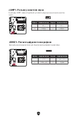
JAUD1

JAMP1

M2_1

DIMMA1

JBAT1

DIMMB1

Компоненты материнской платы

Summary of Contents for H610TI-S01

Page 1: ...H610TI S03 H610TI S01 Motherboard User Guide Benutzerhandbuch Manuel d utilisation...

Page 2: ...English Deutsch Fran ais...

Page 3: ...17 JAUD1 Front Audio Connector 17 JAMP1 Audio Amplifier Connector 18 JDMIC1 Digital Microphone Connector 18 JLVDS1 LVDS Connector 19 JPANELSW1 Panel Display Switch Connector 19 PWR_SEL1 Panel Voltage...

Page 4: ...2 Installing OS Drivers MSI Center 26 UEFI BIOS 27 BIOS Setup 28 Resetting BIOS 29 Updating BIOS 29...

Page 5: ...ing another metal object before handling the motherboard Store the motherboard in an electrostatic shielding container or on an anti static pad whenever the motherboard is not installed Before turning...

Page 6: ...oisture The motherboard does not work well or you can not get it work according to user guide The motherboard has been dropped and damaged The motherboard has obvious sign of breakage Do not leave thi...

Page 7: ...Fi BlueTooth card Onboard Graphics 1x HDMI 2 1 with HDR port supports a maximum resolution of 4K 60Hz 1x DisplayPort 1 4 port supports a maximum resolution of 4K 60Hz For H610 TI S01 only Available on...

Page 8: ...ght inverter voltage selection header LED Features 4x EZ Debug LED Back Panel Connectors For H610 TI S03 1x DC IN connector DC tip size 6 5 x 2 5 mm 1x HDMI port 1x Serial port 1x Clear CMOS button 1x...

Page 9: ...roller Chip Hardware Monitor CPU System Chipset temperature detection CPU System speed detection CPU System speed control Form Factor Mini ITX Form Factor 6 7 in x 6 7 in 17 0 cm x 17 0 cm BIOS Featur...

Page 10: ...6 Item Description 1 DC IN connector DC tip size 6 5 x 2 5 mm 2 HDMI port 3 Serial port 4 Clear CMOS button 5 USB 3 2 Gen 2 10Gbps Type A ports 6 1 Gbps LAN ports 7 USB 3 2 Gen 1 5Gbps Type A ports 8...

Page 11: ...1 Gbps LAN ports 5 USB 3 2 Gen 2 10Gbps Type A Type C ports 6 USB 3 2 Gen 1 5Gbps Type A ports 7 Mic in 8 Line out 5 6 H610 TI S01 LAN Port LED Status Table Link Activity LED Status Description Off No...

Page 12: ...BAT1 CPU_FAN1 Process Socket PWR_SEL1 BKLT_SEL1 JLVDS1 JCONV1 JPANELSW1 JHDDPWR1 JCOM1 JFP1 JTOUCH1 CNVI_1 SATA6 SATA5 JTPM1 JDMIC1 JUSB2 JUSB1 JAUD1 JAMP1 M2_1 DIMMA1 JBAT1 DIMMB1 Overview of Compone...

Page 13: ...f thermal paste or thermal tape between the CPU and the heatsink to enhance heat dissipation Whenever the CPU is not installed always protect the CPU socket pins by covering the socket with the plasti...

Page 14: ...12 Installing a Processor https youtu be KMf9oIDsGes 1 2 3 6 4 5 7 8 9...

Page 15: ...key on the slot and insert the SO DIMM into the slot 2 Push the SO DIMM gently downwards until the slot levers click and lock the SO DIMM in place 1 2 Important You can barely see the golden finger if...

Page 16: ...slot as shown below 1 Move and fasten the M 2 standoff to the appropriate position for your M 2 SSD 2 Insert your M 2 SSD into the M 2 slot at a 30 degree angle 3 Secure the M 2 SSD in place with the...

Page 17: ...slot at a 30 degree angle 2 Secure the M 2 wifi card in place with the supplied M 2 screw 30 30 2 1 Supplied M 2 screw JCOM1 Serial Port Connector This connector allows you to connect the optional ser...

Page 18: ...gle Data loss may result during transmission otherwise SATA cables have identical plugs on either sides of the cable However it is recommended that the flat connector be connected to the motherboard f...

Page 19: ...er LED Reserved Power Switch Reset Switch HDD LED Important Please note that Power LED and HDD LED have positive and negative connection you need to link up the cable to the corresponding positive and...

Page 20: ...o the digital microphone 1 1 Pin Signal Name Pin Signal Name 1 AMP_L 2 AMP_L 3 AMP_R 4 AMP_R JAMP1 Audio Amplifier Connector The JAMP1 is used to enhance audio performance by connecting audio amplifie...

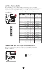
Page 21: ...connector be sure to check the panel datasheet and set the LVDS power connector to the proper power voltage 1 2 Pin Signal Name Pin Signal Name 1 LCD_VDD 2 LCD_VDD 3 LCD_VDD 4 Ground 5 Ground 6 Ground...

Page 22: ...s you to select 3V 5V 12V voltage for the panel 1 1 1 3V 5V 12V JTOUCH1 Touch Panel connector This connector is used to connect the touch panel for adjusting the brightness 1 Pin Signal Name Pin Signa...

Page 23: ...ge for backlight module of the panel 1 1 12V 19V JCONVERT1 FPD Brightness Connector This connector is used to connect an on off switch for the backlight module of the flat panel display 1 Pin Signal N...

Page 24: ...TPM1 TPM Module Connector This connector is for TPM Trusted Platform Module Please refer to the TPM security platform manual for more details and usages Pin Signal Name Pin Signal Name 1 VCC 2 VCC 3 U...

Page 25: ...trol fans in BIOS HARDWARE MONITOR panel Check the Smart Fan Mode the fan speed will change according to the CPU or system temperature Uncheck the Smart Fan Mode the fan will spin at maximum speed 1 P...

Page 26: ...be reset and the data of system configuration will be lost In this case you need to replace the CMOS battery Keep Data default Clear CMOS Reset BIOS Resetting BIOS to default values 1 Power off the c...

Page 27: ...the debug status of the motherboard CPU indicates CPU is not detected or fail DRAM indicates DRAM is not detected or fail VGA indicates GPU is not detected or fail BOOT indicates the booting device i...

Page 28: ...xe to open the installer If you turn off the AutoPlay feature from the Windows Control Panel you can still manually execute the DVDSetup exe from the root path of the MSI USB Drive 4 The installer wil...

Page 29: ...bilities of new devices new devices may not provide backward compatibility Supports secure startup UEFI can check the validity of the operating system to ensure that no malware tampers with the startu...

Page 30: ...to enter Boot Menu message appears on the screen during the boot process Function key F1 General Help list F2 Add Remove a favorite item F3 Enter Favorites menu F4 Enter CPU Specifications menu F5 Ent...

Page 31: ...le into the USB flash drive Updating BIOS 1 Switch to the target BIOS ROM by Multi BIOS switch Please skip this step if your motherboard doesn t has this switch 2 Insert the USB flash drive that conta...

Page 32: ...ting the BIOS To update BIOS 1 Install and launch MSI Center and go to Support page 2 Select Live Update and click on Advance button 3 Select the BIOS file and click on Install button 4 The installati...

Page 33: ...UD1 Audioanschluss des Frontpanels 17 JAMP1 Audioverst rkeranschluss 18 JDMIC1 Digitaler Mikrofonanschluss 18 JLVDS1 LVDS Anschluss 19 JPANELSW1 Anschluss f r Panel Display Schalter 19 PWR_SEL1 Panel...

Page 34: ...2 Installation von OS Treibern MSI Center 26 UEFI BIOS 28 BIOS Setup 29 Reset des BIOS 30 Aktualisierung des BIOS 30...

Page 35: ...ragen Wenn kein elektrostatischen Handgelenkband vorhanden ist sollten Sie Ihre statische Elektrizit t ableiten indem Sie ein anderes Metallobjekt ber hren bevor Sie das Motherboard anfassen Bewahren...

Page 36: ...as Motherboard wurde Feuchtigkeit ausgesetzt Das Motherboard funktioniert nicht richtig oder Sie k nnen es nicht wie in der Bedienungsanleitung beschrieben bedienen Das Motherboard ist heruntergefalle...

Page 37: ...t tzt Wi Fi BlueTooth Karte Onboard Grafik 1x HDMI 2 1 mit HDR Anschluss Unterst tzung einer maximalen Aufl sung von 4K 60Hz 1x DisplayPort 1 4 Anschluss Unterst tzung einer maximalen Aufl sung von 4K...

Page 38: ...uss 1x Serieller Anschluss 1x Touchpanel Anschluss 1x LVDS Anschluss 1x Audioverst rkeranschluss 1x digitaler Mikrofonanschluss 1x FPD Helligkeitsanschluss 1x Anschluss f r Panel Display Schalter Stec...

Page 39: ...5 x 2 5 mm 1x HDMI Anschluss 1x DisplayPort Anschluss 1 x LAN RJ45 Anschluss 1x USB 3 2 Gen2 10Gbit s Typ A Anschluss 1x USB 3 2 Gen2 10Gbit s Typ C Anschluss 2x USB 3 2 Gen1 5Gbit s Typ A Anschl sse...

Page 40: ...ung 1 1x DC IN Anschluss DC Spitzengr e 6 5 x 2 5 mm 2 HDMI Anschluss 3 Serielle Schnittstelle 4 Clear CMOS Taste 5 USB 3 2 Gen 2 10Gbit s Typ A Anschl sse 6 1 Gbit s LAN Anschl sse 7 4x USB 3 2 Gen 1...

Page 41: ...5 USB 3 2 Gen 2 10Gbit s Typ A Typ C Anschl sse 6 USB 3 2 Gen 1 5Gbit s Typ A Anschl sse 7 Mic In 8 Line Out 5 6 H610 TI S01 LAN Port LED Zustandstabelle Verbindung Aktivit t LED Zustand Bezeichnung...

Page 42: ...T1 CPU_FAN1 Prozessor Sockel PWR_SEL1 BKLT_SEL1 JLVDS1 JCONV1 JPANELSW1 JHDDPWR1 JCOM1 JFP1 JTOUCH1 CNVI_1 SATA6 SATA5 JTPM1 JDMIC1 JUSB2 JUSB1 JAUD1 JAMP1 M2_1 DIMMA1 JBAT1 DIMMB1 bersicht der Kompon...

Page 43: ...Tapes zwischen der CPU und dem K hlk rper vorhanden ist um die W rmeableitung zu erh hen Sch tzen Sie den CPU Sockel immer mit der Plastikabdeckung wenn keine CPU installiert ist Verwenden Sie bitte...

Page 44: ...12 Installieren eines Prozessors https youtu be KMf9oIDsGes 1 2 3 6 4 5 7 8 9...

Page 45: ...d setzen Sie das SO DIMM in den Steckplatz ein 2 Dr cken Sie das SO DIMM vorsichtig nach unten bis die Schlitzhebel klicken und das SO DIMM einrasten 1 2 Wichtig Die goldenen Kontakte des Speichermodu...

Page 46: ...ehe unten 1 Entfernen Sie den M 2 Abstandshalter und befestigen Sie ihn an der entsprechenden Position Ihrer M 2 SSD 2 Stecken Sie eine M 2 SSD im 30 Grad Winkel in den M 2 Steckplatz 3 Schrauben Sie...

Page 47: ...d Winkel in den M 2 Steckplatz 2 Schrauben Sie die M 2 WLAN Karte mit 8 5H M 2 Schraube 30 30 2 1 Mitgelieferte M 2 Schraube JCOM1 Serieller Anschluss Mit diesem Anschluss k nnen Sie das optionale ser...

Page 48: ...g Knicken Sie das SATA Kabel nicht in einem 90 Winkel Datenverlust k nnte die Folge sein SATA Kabel haben identische Stecker an beiden Enden Es wird empfohlen den flachen Stecker auf dem Motherboard e...

Page 49: ...er Switch Reset Switch HDD LED Wichtig Bitte beachten Sie dass Power LED und HDD LED eine positive und negative Verbindung haben Sie m ssen das Kabel mit dem entsprechenden positiven und negativen Ans...

Page 50: ...n angeschlossen 1 1 Pin Signalname Pin Signalname 1 AMP_L 2 AMP_L 3 AMP_R 4 AMP_R JAMP1 Audioverst rkeranschluss Der JAMP1 wird zur Verbesserung der Audioleistung durch den Anschluss von Audioverst rk...

Page 51: ...Anschluss angeschlossen haben stellen Sie sicher dass Sie das Datenblatt des Bildschirms pr fen und den LVDS Stromanschluss auf die richtige Stromspannung einstellen 1 2 Pin Signalname Pin Signalname...

Page 52: ...ine Spannung von 3 V 5 V 12 V f r das Panel ausw hlen 1 1 1 3V 5V 12V JTOUCH1 Touchpanel Anschluss Dieser Anschluss wird f r die Verbindung des Touchpanels zur Einstellung der Helligkeit verwendet 1 P...

Page 53: ...as Hintergrundbeleuchtungsmodul des Panels ausw hlen 1 1 12V 19V JCONVERT1 FPD Helligkeitsanschluss ber diesen Anschluss wird ein Ein Ausschalter f r das Hintergrundbeleuchtungsmodul des Flachbildschi...

Page 54: ...MSI Center Dienstprogramm JTPM1 TPM Anschluss Dieser Anschluss wird f r das TPM Modul Trusted Platform Module verwendet Weitere Informationen ber den Einsatz des optionalen TPM Modules entnehmen Sie b...

Page 55: ...OS HARDWARE MONITOR die L fterdrehzahl ndern W hlen Sie den Smart Fan Mode die L ftergeschwindigkeit ndert sich entsprechend der CPU oder Systemtemperatur Deaktivieren Sie den Smart Fan Mode der L fte...

Page 56: ...ration gehen verloren In diesem Fall m ssen Sie die CMOS Batterie ersetzen Daten beibehalten Standardwert CMOS Daten l schen Reset des BIOS R cksetzen des BIOS auf Standardwerte 1 Schalten Sie den Com...

Page 57: ...ug Status des Motherboards an CPU CPU wird nicht erkannt oder ist fehlerhaft DRAM DRAM wird nicht erkannt oder ist fehlerhaft VGA GPU wird nicht erkannt oder ist fehlerhaft BOOT Boot Ger t wird nicht...

Page 58: ...iesen Schritt 7 Folgen Sie den Anweisungen auf dem Bildschirm um das Dienstprogramm Windows 10 Windows 11 zu installieren Installation von Treibern 1 Starten Sie Ihren Computer mit Windows 10 Windows...

Page 59: ...und anderen MSI Produkten steuern und synchronisieren Mit MSI Center k nnen Sie ideale Modi einstellen die Systemleistung berwachen und die L ftergeschwindigkeit anpassen MSI Center Benutzerhandbuch...

Page 60: ...ionen Unterst tzt den vollen Funktionsumfang neuer Ger te neue Ger te bieten m glicherweise keine Abw rtskompatibilit t Unterst tzt sicheren Start UEFI kann die G ltigkeit des Betriebssystems berpr fe...

Page 61: ...Setup Menu F11 to enter Boot Menu erscheint Funktionstasten F1 Allgemeine Hilfe F2 Hinzuf gen Entfernen eines Favoritenpunkts F3 ffnen des Favoriten Men s F4 ffnen des Men s CPU Spezifikationen F5 ff...

Page 62: ...OS Aktualisierungsschritte 1 Wechseln Sie mit dem Multi BIOS Switch zum Ziel BIOS ROM berspringen Sie diesen Schritt wenn Ihr Motherboard diesen Schalter nicht hat 2 Schlie en das USB Flashlaufwerk mi...

Page 63: ...g des BIOS 1 Installieren und starten Sie MSI Center und gehen Sie zur Support Seite 2 W hlen Sie Live Update aus und klicken Sie auf die Schaltfl che Advance 3 W hlen Sie die BIOS Datei aus und klick...

Page 64: ...avant 17 JAUD1 Connecteur audio avant 17 JAMP1 Commutateur d amplificateur audio 18 JDMIC1 Connecteur de microphone num rique 18 JLVDS1 Connecteur LVDS 19 JPANELSW1 Connecteur du commutateur de l cran...

Page 65: ...2 EZ Debug LED 25 Installer OS Pilotes et MSI Center 26 UEFI BIOS 28 Configuration du BIOS 29 R initialiser le BIOS 30 Mettre le BIOS jour 30...

Page 66: ...a carte m re afin de vous d charger de votre charge statique Touchez r guli rement l objet m tallique pendant toute la manipulation Tant que la carte m re n est pas install e conservez la dans un r ci...

Page 67: ...dit La carte m re ne fonctionne pas comme indiqu dans les instructions La carte m re est tomb e par terre et a t endommag e La carte m re est cass e Ne pas mettre la carte m re dans un environnement d...

Page 68: ...compatible Slot d extension 1 x slot M 2 Touche E Support carte Wi Fi et Bluetooth Sorties vid o int gr es 1 x port HDMI 2 1 avec HDR supportant une r solution maximum de 4K 60 Hz 1 x port DisplayPort...

Page 69: ...t me 1 x connecteur de module TPM 1 x connecteur de port s rie 1 x connecteur d cran tactile 1 x connecteur LVDS 1 x commutateur d amplificateur audio 1 x connecteur de microphone num rique 1 x connec...

Page 70: ...Taille de pointe CC 6 5 x 2 5 mm 1 x port HDMI 1 x port DisplayPort 1 x port LAN RJ45 1 x port USB 3 2 Gen 2 10 Gb s Type A 1 x port USB 3 2 Gen 2 10 Gb s Type C 2 x ports USB 3 2 Gen 1 5 Gb s Type A...

Page 71: ...escription 1 Connecteur d entr e CC Taille de pointe CC 6 5 x 2 5 mm 2 Port HDMI 3 Port s rie 4 Bouton Clear CMOS 5 Ports USB 3 2 Gen 2 10 Gb s Type A 6 Port LAN 1 Gb s 7 Ports USB 3 2 Gen 1 5 Gb s Ty...

Page 72: ...b s Type A et Type C 6 Ports USB 3 2 Gen 1 5 Gb s Type A 7 Entr e Microphone 8 Sortie ligne 5 6 H610 TI S01 Tableau explicatif de l tat de la LED du port LAN LED indiquant la connexion et l activit ta...

Page 73: ...CPU_FAN1 Socket processeur PWR_SEL1 BKLT_SEL1 JLVDS1 JCONV1 JPANELSW1 JHDDPWR1 JCOM1 JFP1 JTOUCH1 CNVI_1 SATA6 SATA5 JTPM1 JDMIC1 JUSB2 JUSB1 JAUD1 JAMP1 M2_1 DIMMA1 JBAT1 DIMMB1 Vue d ensemble des co...

Page 74: ...de la surchauffe Assurez vous d appliquer une couche de p te thermique ou adh sif thermique entre le processeur et le syst me de refroidissement afin d am liorer la dissipation de la chaleur Quand le...

Page 75: ...12 Installation d un processeur https youtu be KMf9oIDsGes 1 2 3 6 4 5 7 8 9...

Page 76: ...rez le module SO DIMM dans le slot 2 Poussez doucement le module SO DIMM vers le bas jusqu ce qu il se verrouille en place et que vous entendiez un clic 1 2 Important Vous pouvez peine voir le connec...

Page 77: ...slot M2_1 comme indiqu ci dessous 1 D placez et fixez l entretoise la position appropri e pour le support de votre SSD M 2 2 Ins rez votre SSD M 2 dans le slot M 2 un angle de 30 degr s 3 Fixez le SSD...

Page 78: ...M 2 dans le slot M 2 un angle de 30 degr s 2 Fixez la carte Wi Fi M 2 avec la vis M 2 fournie 30 30 2 1 Vis M 2 JCOM1 Connecteur de port s rie Ce connecteur vous permet de connecter le bracket port s...

Page 79: ...t entra ner une perte de donn es pendant la transmission Les c bles SATA disposent de prises identiques sur chaque c t N anmoins il est recommand de connecter la prise plate sur la carte m re pour un...

Page 80: ...du disque dur 1 2 10 9 Power LED Reserved Power Switch Reset Switch HDD LED Important Veuillez noter que les connecteurs Power LED et HDD LED disposent d un p le n gatif et d un p le positif Vous deve...

Page 81: ...rique 1 1 Broche Nom de signal Broche Nom de signal 1 AMP_L 2 AMP_L 3 AMP_R 4 AMP_R JAMP1 Commutateur d amplificateur audio Le JAMP1 est utilis pour am liorer les performances audio en connectant des...

Page 82: ...S assurez vous de v rifier le tableau de donn es de l cran et r glez le connecteur d alimentation LVDS la tension d alimentation appropri e 1 2 Broche Nom de signal Broche Nom de signal 1 LCD_VDD 2 LC...

Page 83: ...aire votre choix entre les tensions 3 V 5 V 12 V pour l cran LCD 1 1 1 3V 5V 12V JTOUCH1 Connecteur d cran tactile Ce connecteur est utilis pour connecter l cran tactile pour r gler la luminosit 1 Bro...

Page 84: ...12 V 19 V pour le module de r tro clairage de l cran LCD 1 1 12V 19V JCONVERT1 Connecteur de luminosit FPD Ce connecteur est utilis pour connecter un commutateur marche arr t pour le module de r tro...

Page 85: ...e MSI Center JTPM1 Connecteur de module TPM Ce connecteur est reli un module TPM Trusted Platform Module Veuillez vous r f rer au manuel du module TPM pour plus d informations Broche Nom de signal Bro...

Page 86: ...OS HARDWARE MONITOR Si vous cochez le Mode ventilateur intelligent la vitesse du ventilateur changera en fonction de la temp rature du processeur ou du syst me Si vous d cochez le Mode ventilateur int...

Page 87: ...ration du syst me seront perdues Dans ce cas vous devez remplacer la pile CMOS Conserver les donn es d faut Effacer le CMOS R initialiser le BIOS R initialiser le BIOS aux valeurs par d faut 1 teignez...

Page 88: ...ect ou que son initialisation a chou DRAM indique que la m moire DRAM n est pas d tect e ou que son initialisation a chou VGA indique que le GPU n est pas d tect ou que son initialisation a chou BOOT...

Page 89: ...r cette tape 7 Suivez les instructions l cran pour installer Windows 10 Windows 11 Installer les pilotes 1 Allumez l ordinateur sous Windows 10 Windows 11 2 Ins rez la cl USB MSI dans le port USB 3 Cl...

Page 90: ...sur les PC et autres produits MSI Avec MSI Center vous pouvez personnaliser les modes selon vos envies surveiller les performances du syst me et r gler la vitesse du ventilateur Guide d utilisation de...

Page 91: ...pacit s de nouveaux appareils les nouveaux appareils peuvent ne pas fournir de compatibilit descendante Prend en charge le d marrage s curis L UEFI peut v rifier la validit du syst me d exploitation p...

Page 92: ...cran veuillez appuyer sur la touche Suppr Touches de fonction F1 Liste d aide g n rale F2 Ajouter ou supprimer un l ment favori F3 Entrer dans le menu Favoris F4 Entrer dans le menu caract ristiques...

Page 93: ...veuillez sauvegarder le profil BIOS sur la cl USB Mettre le BIOS jour 1 Acc dez au BIOS ROM voulu avec le commutateur Multi BIOS Veuillez ignorer cette tape si votre carte m re ne dispose pas de ce c...

Page 94: ...ttre jour le BIOS Mettre le BIOS jour 1 Installez et lancez MSI Center et acc dez la page Support 2 Choisissez Live Update et cliquez sur le bouton Avanc 3 Choisissez le profil BIOS et cliquez sur le...

Page 95: ...2 E 15 JCOM1 15 SATA5 6 SATA 6 16 JHDDPWR1 SATA 16 JFP1 17 JAUD1 17 JAMP1 18 JDMIC1 18 JLVDS1 LVDS 19 JPANELSW1 19 PWR_SEL1 20 JTOUCH1 20 JCONVERT1 FPD 21 BKLT_SEL1 21 JUSB1 2 USB 2 0 22 JTPM1 22 CPU...

Page 96: ...2 MSI Center 26 UEFI BIOS 27 BIOS 28 BIOS 29 BIOS 29...

Page 97: ...3 MSI URL QR...

Page 98: ...4 60 C 140 F...

Page 99: ...Dual Controller non ECC Intel Extreme Memory Profile XMP www msi com 1x M 2 E Wi Fi Bluetooth 1x HDMI 2 1 HDR 4K 60 1x DisplayPort 1 4 4K 60 H610 TI S01 SATA 2x SATA 6 H610 M 2 SSD 1x M 2 M M2_1 H610...

Page 100: ...6 1x 4 1x 1x 1x TPM 1x 1x 1x LVDS 1x 1x 1x FPD 1x 1x CMOS 1x 1x 4x EZ...

Page 101: ...Type A 2x USB 3 2 Gen1 5 Type A 2x 1 1 H610 TI S01 1x DC 6 5 x 2 5 1x HDMI 1x DisplayPort 1x LAN RJ45 1x USB 3 2 Gen2 10 Type A 1x USB 3 2 Gen2 10 Type C 2x USB 3 2 Gen1 5 Type A 2x 1 1 NUVOTON NCT668...

Page 102: ...8 1 2 3 4 8 9 6 1 DC 6 5 x 2 5 2 HDMI 3 4 CMOS 5 USB 3 2 Gen 2 10 Type A 6 LAN 1 7 USB 3 2 Gen 1 5 Type A 8 9 5 7 H610 TI S03...

Page 103: ...9 1 2 3 4 7 8 1 DC 6 5 x 2 5 2 HDMI 3 DisplayPort 4 LAN 1 5 USB 3 2 Gen 2 10 Type A Type C 6 USB 3 2 Gen 1 5 Type A 7 8 5 6 H610 TI S01 LAN 10 100 1...

Page 104: ...10 BAT1 CPU_FAN1 PWR_SEL1 BKLT_SEL1 JLVDS1 JCONV1 JPANELSW1 JHDDPWR1 JCOM1 JFP1 JTOUCH1 CNVI_1 SATA6 SATA5 JTPM1 JDMIC1 JUSB2 JUSB1 JAUD1 JAMP1 M2_1 DIMMA1 JBAT1 DIMMB1...

Page 105: ...11 MSI MSI LGA1700 LGA1700 1...

Page 106: ...12 https youtu be KMf9oIDsGes 1 2 3 6 4 5 7 8 9...

Page 107: ...13 DIMM SO DIMM 1 SO DIMM SO DIMM SO DIMM 2 SO DIMM SO DIMM 1 2 SO DIMM SO DIMM SO DIMM SO DIMM...

Page 108: ...14 M2_1 M 2 M M 2 SSD M2_1 1 M 2 M 2 SSD 2 M 2 SSD 2 30 3 M 2 SSD M 2 30 30 2 3 1 M 2 M 2...

Page 109: ...15 CNVI_1 M 2 E Wi Fi CNVI_1 1 M 2 wifi 2 30 2 M 2 wifi M 2 30 30 2 1 M 2 JCOM1 1 DCD 2 SIN 3 SOUT 4 DTR 5 Ground 6 DSR 7 RTS 8 CTS 9 RI 10 No Pin 1 2 10 9...

Page 110: ...16 SATA5 6 SATA 6 SATA 6 SATA SATA SATA SATA5 SATA6 JHDDPWR1 SATA SATA 1 1 VCC5 2 Ground 3 Ground 4 12V...

Page 111: ...h Power LED HDD LED 1 2 10 9 Power LED Reserved Power Switch Reset Switch HDD LED Power LED HDD LED JAUD1 1 2 10 9 1 MIC L 2 Ground 3 MIC R 4 NC 5 Head Phone R 6 MIC Detection 7 SENSE_SEND 8 No Pin 9...

Page 112: ...18 JDMIC1 1 1 1 AMP_L 2 AMP_L 3 AMP_R 4 AMP_R JAMP1 JAMP1 1 VCC3 2 DMIC_DATA 3 DMIC_CLK 4 Ground...

Page 113: ...round 6 Ground 7 LVDSA_DATA0 8 LVDSA_DATA0 9 LVDSA_DATA1 10 LVDSA_DATA1 11 LVDSA_DATA2 12 LVDSA_DATA2 13 Ground 14 Ground 15 LVDSA_CLK 16 LVDSA_CLK 17 LVDSA_DATA3 18 LVDSA_DATA3 19 LVDSA_DATA0 20 LVDS...

Page 114: ...20 PWR_SEL1 3 5 12 1 1 1 3V 5V 12V JTOUCH1 1 1 5V_TOUCH 2 MB_USB_9D 3 MB_USB_9D 4 Ground 5 Ground...

Page 115: ...21 BKLT_SEL1 12 19 1 1 12V 19V JCONVERT1 FPD 1 1 L_BKLTEN 2 L_BKLTCTL 3 BKLT_VCC 4 BKLT_VCC 5 Ground 6 Ground 7 SEL_UP 8 SEL_DOWN...

Page 116: ...odule 1 VCC 2 VCC 3 USB0 4 USB1 5 USB0 6 USB1 7 Ground 8 Ground 9 No Pin 10 NC 1 2 10 9 1 SPI Power 2 SPI Chip Select 3 Master In Slave Out SPI Data 4 Master Out Slave In SPI Data 5 Reserved 6 SPI Clo...

Page 117: ...23 CPU_FAN1 PWM Pulse Width Modulation PWM 12 BIOS HARDWARE MONITOR Smart Fan Mode 1 PWM 1 Ground 2 12V 3 Sense 4 Speed Control Signal CPU_FAN1 PWM 2 24...

Page 118: ...24 JBAT1 CMOS BIOS CMOS CMOS BAT1 CMOS CMOS BIOS CMOS BIOS BIOS 1 2 JBAT1 5 10 3 JBAT1 4 CMOS 1 BAT1 2 CR2032 BAT1...

Page 119: ...25 EZ CPU DRAM DRAM VGA BOOT...

Page 120: ...y to boot from CD or DVD 7 Windows 10 Windows 11 1 Windows 10 Windows 11 2 USB MSI USB Drive 3 Select to choose what happens with this disc Run DVDSetup exe Windows DVDSetup exe USB MSI USB Drive 4 Dr...

Page 121: ...EFI BIOS UEFI BIOS UEFI BIOS UEFI UEFI BIOS CSM POST 2 4 GUID GPT UEFI UEFI 32 Windows Windows 10 Windows 11 64 There is no GOP Graphics Output protocol support detected in this graphics card GOP UEFI...

Page 122: ...OS HELP BIOS BIOS Delete Press DEL key to enter Setup Menu F11 to enter Boot Menu F1 F2 F3 F4 F5 Memory Z F6 F7 EZ F8 F9 F10 F12 USB FAT FAT32 Ctrl F F10 Yes No BIOS BIOS http download msi com manual...

Page 123: ...F6 CMOS CMOS BIOS CMOS BIOS BIOS M FLASH BIOS MSI BIOS USB BIOS 1 BIOS ROM Multi BIOS 2 USB USB 3 Ctrl F5 POST Yes Press Ctrl F5 to activate M Flash for BIOS update Del POST BIOS M FLASH Yes 4 BIOS B...

Page 124: ...30 BIOS MSI Center BIOS BIOS 1 MSI Center Support 2 Live Update Advance 3 BIOS Install 4 Install 5 BIOS 6...

Page 125: ...y E 15 JCOM1 15 SATA5 6 SATA 6Gb s 16 JHDDPWR1 SATA 16 JFP1 17 JAUD1 17 JAMP1 18 JDMIC1 18 JLVDS1 LVDS 19 JPANELSW1 19 PWR_SEL1 20 JTOUCH1 20 JCONVERT1 FPD 21 BKLT_SEL1 21 JUSB1 2 USB 2 0 22 JTPM1 TPM...

Page 126: ...2 OS MSI Center 26 UEFI BIOS 27 BIOS 28 BIOS 29 BIOS 29...

Page 127: ...3 MSI Web URL QR ESD PC ESD ESD PC PC PC PC PC...

Page 128: ...4 PC 60OC 140OF...

Page 129: ...buffered Intel Extreme Memory Profile XMP www msi com M 2 x1 Key E Wi Fi BlueTooth HDR HDMI 2 1 x1 4K 60Hz DisplayPort 1 4 x1 4K 60Hz H610 TI S01 GPU CPU SATA SATA 6Gb s x2 H610 M 2 SSD M 2 x1 Key M...

Page 130: ...DC IN x1 DC 6 5 x 2 5 mm HDMI x1 x1 CMOS x1 LAN RJ45 x1 USB 3 2 Gen2 10Gbps Type A x2 USB 3 2 Gen1 5Gbps Type A x2 x2 1 1 H610 TI S01 DC IN x1 DC 6 5 x 2 5 mm HDMI x1 DisplayPort x1 LAN RJ45 x1 USB 3...

Page 131: ...7 I O NUVOTON NCT6687 R CPU CPU CPU Mini ITX 6 7 in x 6 7 in 17 0 cm x 17 0 cm BIOS 128 Mb x1 UEFI AMI BIOS ACPI 6 2 SMBIOS 3 2...

Page 132: ...8 1 2 3 4 8 9 6 1 DC IN DC 6 5 x 2 5 mm 2 HDMI 3 4 CMOS 5 USB 3 2 Gen 2 10Gbps Type A 6 1 Gbps LAN 7 USB 3 2 Gen 1 5Gbps Type A 8 9 5 7 H610 TI S03...

Page 133: ...2 3 4 7 8 1 DC IN DC 6 5 x 2 5 mm 2 HDMI 3 DisplayPort 4 1 Gbps LAN 5 USB 3 2 Gen 2 10Gbps Type A Type C 6 USB 3 2 Gen 1 5Gbps Type A 7 8 5 6 H610 TI S01 LAN LED LED Off LED Off 10 Mbps 100 Mbps 1 Gb...

Page 134: ...10 BAT1 CPU_FAN1 PWR_SEL1 BKLT_SEL1 JLVDS1 JCONV1 JPANELSW1 JHDDPWR1 JCOM1 JFP1 JTOUCH1 CNVI_1 SATA6 SATA5 JTPM1 JDMIC1 JUSB2 JUSB1 JAUD1 JAMP1 M2_1 DIMMA1 JBAT1 DIMMB1...

Page 135: ...11 CPU CPU CPU CPU CPU CPU CPU CPU CPU CPU CPU CPU CPU CPU CPU CPU CPU CPU CPU CPU CPU MSI CPU LGA1700 CPU LGA1700 CPU 4 1...

Page 136: ...12 https youtu be KMf9oIDsGes 1 2 3 6 4 5 7 8 9...

Page 137: ...13 SO DIMM SO DIMM 1 SO DIMM SO DIMM SO DIMM 2 SO DIMM SO DIMM 1 2 SO DIMM SO DIMM SO DIMM SO DIMM...

Page 138: ...14 M2_1 M 2 Key M M 2 SSD M2_1 1 M 2 M 2 SSD 2 30 M 2 SSD M 2 3 M 2 M 2 SSD 30 30 2 3 1 M 2 M 2...

Page 139: ...15 CNVI_1 M 2 Key E Wi Fi CNVI_1 1 30 M 2 wifi M 2 2 M 2 M 2 wifi 30 30 2 1 M 2 JCOM1 1 DCD 2 SIN 3 SOUT 4 DTR 5 Ground 6 DSR 7 RTS 8 CTS 9 RI 10 No Pin 1 2 10 9...

Page 140: ...16 SATA5 6 SATA 6Gb s SATA 6Gb s SATA SATA 90 SATA SATA5 SATA6 JHDDPWR1 SATA SATA 1 1 VCC5 2 Ground 3 Ground 4 12V...

Page 141: ...Power LED PC LED HDD LED 1 2 10 9 Power LED Reserved Power Switch Reset Switch HDD LED Power LED HDD LED LED JAUD1 1 2 10 9 1 MIC L 2 Ground 3 MIC R 4 NC 5 Head Phone R 6 MIC Detection 7 SENSE_SEND 8...

Page 142: ...18 JDMIC1 1 1 1 AMP_L 2 AMP_L 3 AMP_R 4 AMP_R JAMP1 JAMP1 1 VCC3 2 DMIC_DATA 3 DMIC_CLK 4 Ground...

Page 143: ...round 6 Ground 7 LVDSA_DATA0 8 LVDSA_DATA0 9 LVDSA_DATA1 10 LVDSA_DATA1 11 LVDSA_DATA2 12 LVDSA_DATA2 13 Ground 14 Ground 15 LVDSA_CLK 16 LVDSA_CLK 17 LVDSA_DATA3 18 LVDSA_DATA3 19 LVDSA_DATA0 20 LVDS...

Page 144: ...20 PWR_SEL1 3V 5V 12V 1 1 1 3V 5V 12V JTOUCH1 1 1 5V_TOUCH 2 MB_USB_9D 3 MB_USB_9D 4 Ground 5 Ground...

Page 145: ...21 BKLT_SEL1 12V 19V 1 1 12V 19V JCONVERT1 FPD 1 1 L_BKLTEN 2 L_BKLTCTL 3 BKLT_VCC 4 BKLT_VCC 5 Ground 6 Ground 7 SEL_UP 8 SEL_DOWN...

Page 146: ...Module TPM 1 VCC 2 VCC 3 USB0 4 USB1 5 USB0 6 USB1 7 Ground 8 Ground 9 No Pin 10 NC 1 2 10 9 1 SPI Power 2 SPI Chip Select 3 Master In Slave Out SPI Data 4 Master Out Slave In SPI Data 5 Reserved 6 S...

Page 147: ...23 CPU_FAN1 CPU PWM PWM 12V BIOS HARDWARE MONITOR CPU 1 PWM 1 Ground 2 12V 3 Sense 4 Speed Control Signal CPU_FAN1 PWM 2A 24W...

Page 148: ...24 JBAT1 CMOS BIOS CMOS CMOS BAT1 CMOS CMOS BIOS CMOS CMOS BIOS BIOS 1 PC 2 JBAT1 5 10 3 JBAT1 4 CMOS 1 BAT1 2 CR2032 BAT1...

Page 149: ...25 EZ Debug LED LED CPU CPU DRAM DRAM VGA GPU BOOT LED...

Page 150: ...any key to boot from CD or DVD Enter 7 Windows 10 Windows 11 1 Windows 10 Windows 11 2 MSI USB USB 3 Select to choose what happens with this disc Run DVDSetup exe Windows MSI USB DVDSetup exe 4 5 Ins...

Page 151: ...S MSI UEFI BIOS UEFI BIOS UEFI BIOS UEFI UEFI BIOS POST CSM 2 TB GUID Partition Table GPT 4 UEFI UEFI 32 Windows Windows 10 Windows 11 64 GOP Graphics Output Protocol GOP UEFI CPU BIOS 1 PC 2 Press DE...

Page 152: ...s DEL key to enter Setup Menu F11 to enter Boot Menu Delete F1 F2 Favorites F3 Favorites F4 CPU F5 Memory Z F6 optimized defaults F7 EZ F8 OC F9 OC F10 F12 USB FAT FAT32 Ctrl F F10 Yes No BIOS BIOS ht...

Page 153: ...ized defaults CMOS CMOS PC BIOS CMOS BIOS M FLASH BIOS MSI WEB BIOS USB BIOS 1 BIOS BIOS ROM 2 BIOS USB USB 3 POST Ctrl F5 Yes Press Ctrl F5 to activate M Flash for BIOS update POST Delete BIOS M FLAS...

Page 154: ...30 MSI Center BIOS LAN BIOS 1 MSI CENTER Support 2 Live Update Advanced 3 BIOS Install 4 Install 5 BIOS 6...

Page 155: ...E 15 JCOM1 15 SATA5 6 SATA 6Gb s 16 JHDDPWR1 SATA 16 JFP1 17 JAUD1 17 JAMP1 18 JDMIC1 18 JLVDS1 LVDS 19 JPANELSW1 19 PWR_SEL1 20 JTOUCH1 20 JCONVERT1 FPD 21 BKLT_SEL1 21 JUSB1 2 USB 2 0 22 JTPM1 TPM...

Page 156: ...2 OS MSI 26 UEFI BIOS 27 BIOS 28 BIOS 29 BIOS 29...

Page 157: ...3 MSI URL QR URL ESD ESD ESD PSU PSU...

Page 158: ...4 60 C 140 F...

Page 159: ...n ECC un buffered XMP www msi com 1x M 2 Key M Wi Fi 1x HDR HDMI 2 1 4K 60Hz 1x 1 4 4K 60Hz H610 TI S01 CPU SATA 2x SATA 6Gb s H610 M 2 SSD 1x M 2 Key M M2_1 H610 PCIe 3 0 x4 2280 Realtek ALC897 LAN 1...

Page 160: ...S03 1x DC IN DC 6 5 x 2 5 mm 1x HDMI 1x 1x CMOS 1x LAN RJ45 2x USB 3 2 Gen2 10Gbps Type A 2x USB 3 2 Gen1 5Gbps Type A 2x 1 1 H610 TI S01 1x DC IN DC 6 5 x 2 5 mm 1x HDMI 1x 1x LAN RJ45 1x USB 3 2 Gen...

Page 161: ...7 I O NUVOTON NCT6687 R CPU CPU CPU Mini ITX 6 7 in x 6 7 in 17 0 cm x 17 0 cm BIOS 1x 128 Mb flash UEFI AMI BIOS ACPI 6 2 SMBIOS 3 2...

Page 162: ...8 1 2 3 4 8 9 6 1 DC IN DC 6 5 x 2 5 mm 2 HDMI 3 4 CMOS 5 USB 3 2 Gen 2 10Gbps Type A 6 1 Gbps LAN 7 USB 3 2 Gen 1 5Gbps Type A 8 9 5 7 H610 TI S03...

Page 163: ...9 1 2 3 4 7 8 1 DC IN DC 6 5 x 2 5 mm 2 HDMI 3 4 1 Gbps LAN 5 USB 3 2 Gen 2 10Gbps Type A Type C 6 USB 3 2 Gen 1 5Gbps Type A 7 8 5 6 H610 TI S01 LAN LED LED LAN LED 10 Mbps 100 Mbps 1 Gbps...

Page 164: ...10 BAT1 CPU_FAN1 PWR_SEL1 BKLT_SEL1 JLVDS1 JCONV1 JPANELSW1 JHDDPWR1 JCOM1 JFP1 JTOUCH1 CNVI_1 SATA6 SATA5 JTPM1 JDMIC1 JUSB2 JUSB1 JAUD1 JAMP1 M2_1 DIMMA1 JBAT1 DIMMB1...

Page 165: ...11 CPU CPU CPU MSI RMA CPU CPU CPU CPU CPU CPU CPU CPU CPU CPU MSI CPU LGA1700 CPU LGA1700 CPU 4 1 CPU 1...

Page 166: ...12 https youtu be KMf9oIDsGes 1 2 3 6 4 5 7 8 9...

Page 167: ...13 SO DIMM SO DIMM 1 SO DIMM SO DIMM SO DIMM 2 SO DIMM 1 2 SO DIMM SO DIMM SO DIMM SO DIMM...

Page 168: ...14 M2_1 M 2 Key M M 2 SSD M2_1 1 M 2 M 2 SSD 2 M 2 SSD M 2 30 3 M 2 M 2 SSD 30 30 2 3 1 M 2 M 2...

Page 169: ...15 CNVI_1 M 2 Key E Wi Fi CNVI_1 1 M 2 SSD M 2 30 2 M 2 M 2 Wi Fi 30 30 2 1 M 2 JCOM1 1 DCD 2 SIN 3 SOUT 4 DTR 5 Ground 6 DSR 7 RTS 8 CTS 9 RI 10 No Pin 1 2 10 9...

Page 170: ...16 SATA5 6 SATA 6Gb s SATA 6Gb s SATA SATA 90 SATA SATA5 SATA6 JHDDPWR1 SATA SATA 1 1 VCC5 2 Ground 3 Ground 4 12V...

Page 171: ...1 PC LED LED PC LED HDD LED 1 2 10 9 LED Reserved HDD LED LED HDD LED LED JAUD1 1 2 10 9 1 MIC L 2 Ground 3 MIC R 4 NC 5 Head Phone R 6 MIC Detection 7 SENSE_SEND 8 No Pin 9 Head Phone L 10 Head Phone...

Page 172: ...18 JDMIC1 1 1 1 AMP_L 2 AMP_L 3 AMP_R 4 AMP_R JAMP1 JAMP1 1 VCC3 2 DMIC_DATA 3 DMIC_CLK 4 Ground...

Page 173: ...round 6 Ground 7 LVDSA_DATA0 8 LVDSA_DATA0 9 LVDSA_DATA1 10 LVDSA_DATA1 11 LVDSA_DATA2 12 LVDSA_DATA2 13 Ground 14 Ground 15 LVDSA_CLK 16 LVDSA_CLK 17 LVDSA_DATA3 18 LVDSA_DATA3 19 LVDSA_DATA0 20 LVDS...

Page 174: ...20 PWR_SEL1 3V 5V 12V 1 1 1 3V 5V 12V JTOUCH1 1 1 5V_TOUCH 2 MB_USB_9D 3 MB_USB_9D 4 Ground 5 Ground...

Page 175: ...21 BKLT_SEL1 12V 19V 1 1 12V 19V JCONVERT1 FPD 1 1 L_BKLTEN 2 L_BKLTCTL 3 BKLT_VCC 4 BKLT_VCC 5 Ground 6 Ground 7 SEL_UP 8 SEL_DOWN...

Page 176: ...Module TPM 1 VCC 2 VCC 3 USB0 4 USB1 5 USB0 6 USB1 7 Ground 8 Ground 9 No Pin 10 NC 1 2 10 9 1 SPI Power 2 SPI Chip Select 3 Master In Slave Out SPI Data 4 Master Out Slave In SPI Data 5 Reserved 6 S...

Page 177: ...23 CPU_FAN1 CPU PWM Pulse Width Modulation PWM 12V BIOS HARDWARE MONITOR CPU 1 PWM 1 Ground 2 12V 3 Sense 4 Speed Control Signal CPU_FAN1 PWM 2A 24W...

Page 178: ...24 JBAT1 CMOS Reset BIOS CMOS CMOS BAT1 CMOS CMOS BIOS CMOS CMOS BIOS BIOS 1 2 JBAT1 5 10 3 JBAT1 4 CMOS 1 BAT1 2 CR2032 BAT1...

Page 179: ...25 EZ LED LED CPU CPU DRAM DRAM VGA GPU BOOT LEDs...

Page 180: ...s any key to boot from CD or DVD message 7 Windows 10 Windows 11 1 Windows 10 Windows 11 2 MSI USB USB 3 Select to choose what happens with this disc Run DVDSetup exe Windows MSI USB DVDSetup exe 4 Dr...

Page 181: ...le Firmware Interface UEFI BIOS BIOS MSI UEFI BIOS UEFI BIOS UEFI BIOS UEFI UEFI BIOS POST CSM 2TB GUID GPT 4 UEFI UEFI 32 Windows Windows 10 Windows 11 64 GOP Graphics Output Protocol GOP UEFI CPU BI...

Page 182: ...BIOS BIOS BIOS BIOS BIOS HELP BIOS BIOS DEL F11 Delete F1 F2 F3 F4 CPU F5 Memory Z Z F6 F7 EZ F8 F9 F10 F12 USB FAT FAT32 Ctrl F F10 Yes No BIOS BIOS http download msi com manual mb Intel600BIOSkr pdf...

Page 183: ...S F6 CMOS CMOS BIOS CMOS BIOS M FLASH BIOS BIOS MSI BIOS USB BIOS 1 Multi BIOS BIOS ROM 2 USB USB 3 POST Ctrl F5 Yes Press Ctrl F5 to activate M Flash for BIOS update BIOS POST Del M FLASH Yes 4 BIOS...

Page 184: ...30 MSI Center BIOS LAN BIOS BIOS 1 MSI Support 2 Live Update Advance 3 BIOS Install 4 Install 5 BIOS 6 BIOS 100...

Page 185: ...E 14 JCOM1 14 SATA5 6 SATA 6Gb s 15 JHDDPWR1 SATA 15 JFP1 16 JAUD1 16 JAMP1 17 JDMIC1 17 JLVDS1 LVDS 18 JPANELSW1 18 PWR_SEL1 19 JTOUCH1 19 JCONVERT1 FPD 20 BKLT_SEL1 20 JUSB1 2 USB 2 0 21 JTPM1 TPM 2...

Page 186: ...2 MSI Center 25 UEFI BIOS 26 BIOS 27 BIOS 28 BIOS 28...

Page 187: ...3 MSI ESD 60 C 140 F...

Page 188: ...933 3200 MHz non ECC Intel Extreme Memory Profile XMP www msi com 1 M 2 E Wi Fi 1 HDR HDMI 2 1 4K 60Hz 1 DisplayPort 1 4 4K 60Hz H610 TI S01 SATA 2 SATA 6Gb s H610 M 2 SSD 1 M 2 M M2_1 H610 PCIe 3 0 x...

Page 189: ...S03 1 DC DC 6 5 x 2 5 1 HDMI 1 1 CMOS 1 LAN RJ45 2 USB 3 2 Gen2 10Gbps Type A 2 USB 3 2 Gen1 5Gbps Type A 2 1 1 H610 TI S01 1 DC DC 6 5 x 2 5 1 HDMI 1 DisplayPort 1 LAN RJ45 1 USB 3 2 Gen2 10Gbps Typ...

Page 190: ...6 I O NUVOTON NCT6687 R CPU CPU CPU Mini ITX 6 7 x 6 7 17 0 x 17 0 BIOS 1 128 Mb flash UEFI AMI BIOS ACPI 6 2 SMBIOS 3 2...

Page 191: ...7 1 2 3 4 8 9 6 1 DC DC 6 5 x 2 5 2 HDMI 3 4 CMOS 5 USB 3 2 Gen 2 10Gbps Type A 6 1 Gbps 7 USB 3 2 Gen 1 5Gbps Type A 8 9 5 7 H610 TI S03...

Page 192: ...8 1 2 3 4 7 8 1 DC DC 6 5 x 2 5 2 HDMI 3 DisplayPort 4 1 Gbps 5 USB 3 2 Gen 2 10Gbps Type A Type C 6 USB 3 2 Gen 1 5Gbps Type A 7 8 5 6 H610 TI S01 LED 10 Mbps 100 Mbps 1 Gbps...

Page 193: ...9 BAT1 CPU_FAN1 PWR_SEL1 BKLT_SEL1 JLVDS1 JCONV1 JPANELSW1 JHDDPWR1 JCOM1 JFP1 JTOUCH1 CNVI_1 SATA6 SATA5 JTPM1 JDMIC1 JUSB2 JUSB1 JAUD1 JAMP1 M2_1 DIMMA1 JBAT1 DIMMB1...

Page 194: ...10 CPU CPU Return Merchandise Authorization RMA CPU CPU CPU CPU CPU CPU CPU CPU MSI CPU LGA1700 CPU LGA1700 CPU...

Page 195: ...11 https youtu be KMf9oIDsGes 1 2 3 6 4 5 7 8 9...

Page 196: ...12 SO DIMM SO DIMM 1 SO DIMM SO DIMM SO DIMM 2 SO DIMM SO DIMM 1 2 SO DIMM SO DIMM SO DIMM SO DIMM...

Page 197: ...13 M2_1 M 2 M M 2 SSD M2_1 1 M 2 M 2 SSD 2 M 2 SSD 30 M 2 3 M 2 SSD M 2 30 30 2 3 1 M 2 M 2...

Page 198: ...14 CNVI_1 M 2 E Wi Fi CNVI_1 1 M 2 wifi 30 M 2 2 M 2 wifi M 2 30 30 2 1 M 2 JCOM1 1 DCD 2 SIN 3 SOUT 4 DTR 5 Ground 6 DSR 7 RTS 8 CTS 9 RI 10 No Pin 1 2 10 9...

Page 199: ...15 SATA5 6 SATA 6Gb s SATA 6Gb s SATA SATA 90 SATA SATA5 SATA6 JHDDPWR1 SATA SATA 1 1 VCC5 2 Ground 3 Ground 4 12V...

Page 200: ...Power LED LED HDD LED 1 2 10 9 Power LED Reserved Power Switch Reset Switch HDD LED Power LED HDD LED LED JAUD1 1 2 10 9 1 MIC L 2 Ground 3 MIC R 4 NC 5 Head Phone R 6 MIC Detection 7 SENSE_SEND 8 No...

Page 201: ...17 JDMIC1 1 1 1 AMP_L 2 AMP_L 3 AMP_R 4 AMP_R JAMP1 JAMP1 1 VCC3 2 DMIC_DATA 3 DMIC_CLK 4 Ground...

Page 202: ...round 6 Ground 7 LVDSA_DATA0 8 LVDSA_DATA0 9 LVDSA_DATA1 10 LVDSA_DATA1 11 LVDSA_DATA2 12 LVDSA_DATA2 13 Ground 14 Ground 15 LVDSA_CLK 16 LVDSA_CLK 17 LVDSA_DATA3 18 LVDSA_DATA3 19 LVDSA_DATA0 20 LVDS...

Page 203: ...19 PWR_SEL1 3V 5V 12V 1 1 1 3V 5V 12V JTOUCH1 1 1 5V_TOUCH 2 MB_USB_9D 3 MB_USB_9D 4 Ground 5 Ground...

Page 204: ...20 BKLT_SEL1 12V 19V 1 1 12V 19V JCONVERT1 FPD 1 1 L_BKLTEN 2 L_BKLTCTL 3 BKLT_VCC 4 BKLT_VCC 5 Ground 6 Ground 7 SEL_UP 8 SEL_DOWN...

Page 205: ...1 VCC 2 VCC 3 USB0 4 USB1 5 USB0 6 USB1 7 Ground 8 Ground 9 No Pin 10 NC 1 2 10 9 1 SPI Power 2 SPI Chip Select 3 Master In Slave Out SPI Data 4 Master Out Slave In SPI Data 5 Reserved 6 SPI Clock 7 G...

Page 206: ...22 CPU_FAN1 CPU PWM PWM 12V BIOS HARDWARE MONITOR CPU 1 PWM 1 Ground 2 12V 3 Sense 4 Speed Control Signal CPU_FAN1 PWM 2A 24W...

Page 207: ...23 JBAT1 CMOS BIOS CMOS CMOS BAT1 CMOS CMOS BIOS CMOS CMOS BIOS BIOS 1 2 JBAT1 5 10 3 JBAT1 4 CMOS 1 2 CR2032 BAT1...

Page 208: ...24 LED LED CPU CPU DRAM VGA BOOT LED...

Page 209: ...Windows 10 Windows 11 USB 6 Press any key to boot from CD or DVD 7 Windows 10 Windows 11 1 Windows 10 Windows 11 2 MSI USB USB 3 DVDSetup exe Windows MSI USB DVDSetup exe 4 5 6 7 8 MSI Center MSI Cen...

Page 210: ...UEFI BIOS UEFI BIOS UEFI BIOS UEFI UEFI BIOS POST CSM 2 TB GUID GPT UEFI UEFI 32 Windows 64 Windows 10 Windows 11 There is no GOP Graphics Output protocol support detected in this graphics card GOP G...

Page 211: ...27 BIOS BIOS BIOS BIOS HELP BIOS BIOS BIOS DEL F11 Delete F1 F2 F3 F4 CPU F5 Memory Z F6 F7 EZ F8 F9 F10 F12 USB FAT FAT32 Ctrl F F10 BIOS BIOS http download msi com manual mb Intel600BIOStc pdf...

Page 212: ...BIOS F6 CMOS CMOS CMOS BIOS BIOS M FLASH BIOS MSI BIOS BIOS USB BIOS 1 BIOS BIOS ROM 2 USB USB 3 POST Ctrl F5 Yes Press Ctrl F5 to activate M Flash for BIOS update POST Del BIOS M FLASH Yes 4 BIOS BIO...

Page 213: ...29 MSI Center BIOS BIOS BIOS 1 MSI Center Support 2 Live Update Advance 3 BIOS Install 4 Install 5 BIOS 6 100...

Page 214: ...VI_1 M 2 E 14 JCOM1 14 SATA5 6 SATA 6Gb s 15 JHDDPWR1 SATA 15 JFP1 16 JAUD1 16 JAMP1 17 JDMIC1 17 JLVDS1 LVDS 18 JPANELSW1 18 PWR_SEL1 19 JTOUCH1 19 JCONVERT1 FPD 20 BKLT_SEL1 20 JUSB1 2 USB 2 0 21 JT...

Page 215: ...2 LED 24 LED 24 MSI Center 25 UEFI BIOS 26 BIOS 27 BIOS 28 BIOS 28...

Page 216: ...3 MSI URL ESD ESD ESD 60 140...

Page 217: ...33 2666 2933 3200 MHz ECC Intel XMP www msi com 1 M 2 E Wi Fi 1 HDR HDMI 2 1 4K 60Hz 1 DisplayPort 1 4 4K 60Hz H610 TI S01 CPU SATA 2 SATA 6Gb s H610 M 2 1 M 2 M M2_1 H610 PCIe 3 0 x4 2280 Realtek ALC...

Page 218: ...03 1 DC DC 6 5 x 2 5 1 HDMI 1 1 CMOS 1 LAN RJ45 2 USB 3 2 Gen2 10Gbps Type A 2 USB 3 2 Gen1 5Gbps Type A 2 1 1 H610 TI S01 1 DC DC 6 5 x 2 5 1 HDMI 1 DisplayPort 1 LAN RJ45 1 USB 3 2 Gen2 10Gbps Type...

Page 219: ...6 I O NUVOTON NCT6687 R CPU CPU CPU Mini ITX 6 7 x 6 7 17 0 x 17 0 BIOS 1 128 Mb flash UEFI AMI BIOS ACPI 6 2 SMBIOS 3 2...

Page 220: ...7 1 2 3 4 8 9 6 1 DC DC 6 5 x 2 5 2 HDMI 3 4 CMOS 5 USB 3 2 Gen 2 10Gbps Type A 6 1 Gbps LAN 7 USB 3 2 Gen 1 5Gbps Type A 8 9 5 7 H610 TI S03...

Page 221: ...8 1 2 3 4 7 8 1 DC DC 6 5 x 2 5 2 HDMI 3 DisplayPort 4 1 Gbps LAN 5 USB 3 2 Gen 2 10Gbps Type A Type C 6 USB 3 2 Gen 1 5Gbps Type A 7 8 5 6 H610 TI S01 LAN LED 10 Mbps 100 Mbps 1 Gbps...

Page 222: ...9 BAT1 CPU_FAN1 PWR_SEL1 BKLT_SEL1 JLVDS1 JCONV1 JPANELSW1 JHDDPWR1 JCOM1 JFP1 JTOUCH1 CNVI_1 SATA6 SATA5 JTPM1 JDMIC1 JUSB2 JUSB1 JAUD1 JAMP1 M2_1 DIMMA1 JBAT1 DIMMB1...

Page 223: ...10 CPU CPU RMA CPU CPU CPU CPU CPU CPU CPU CPU CPU CPU CPU CPU MSI CPU LGA1700 CPU CPU LGA1700 CPU Pin 1...

Page 224: ...11 https v youku com v_show id_XNTE5NDQwNDY2NA html 1 2 3 6 4 5 7 8 9...

Page 225: ...12 SO DIMM SO DIMM 1 SO DIMM SO DIMM SO DIMM 2 SO DIMM SO DIMM 1 2 SO DIMM SO DIMM SO DIMM SO DIMM...

Page 226: ...13 M2_1 M 2 M M 2 M2_1 1 M 2 M 2 2 M 2 30 M 2 3 M 2 M 2 30 30 2 3 1 M 2 M 2...

Page 227: ...14 CNVI_1 M 2 E Wi Fi CNVI_1 1 M 2 wifi 30 M 2 2 M 2 M 2 wifi 30 30 2 1 M 2 JCOM1 1 DCD 2 SIN 3 SOUT 4 DTR 5 Ground 6 DSR 7 RTS 8 CTS 9 RI 10 No Pin 1 2 10 9...

Page 228: ...15 SATA5 6 SATA 6Gb s SATA 6Gb s SATA SATA 90 SATA SATA5 SATA6 JHDDPWR1 SATA SATA 1 1 VCC5 2 Ground 3 Ground 4 12V...

Page 229: ...HDD LED 1 2 10 9 Power LED Reserved Power Switch Reset Switch HDD LED Power LED HDD LED LED JAUD1 1 2 10 9 1 MIC L 2 Ground 3 MIC R 4 NC 5 Head Phone R 6 MIC Detection 7 SENSE_SEND 8 No Pin 9 Head Ph...

Page 230: ...17 JDMIC1 1 1 1 AMP_L 2 AMP_L 3 AMP_R 4 AMP_R JAMP1 JAMP1 1 VCC3 2 DMIC_DATA 3 DMIC_CLK 4 Ground...

Page 231: ...round 6 Ground 7 LVDSA_DATA0 8 LVDSA_DATA0 9 LVDSA_DATA1 10 LVDSA_DATA1 11 LVDSA_DATA2 12 LVDSA_DATA2 13 Ground 14 Ground 15 LVDSA_CLK 16 LVDSA_CLK 17 LVDSA_DATA3 18 LVDSA_DATA3 19 LVDSA_DATA0 20 LVDS...

Page 232: ...19 PWR_SEL1 3V 5V 12V 1 1 1 3V 5V 12V JTOUCH1 1 1 5V_TOUCH 2 MB_USB_9D 3 MB_USB_9D 4 Ground 5 Ground...

Page 233: ...20 BKLT_SEL1 12V 19V 1 1 12V 19V JCONVERT1 FPD 1 1 L_BKLTEN 2 L_BKLTCTL 3 BKLT_VCC 4 BKLT_VCC 5 Ground 6 Ground 7 SEL_UP 8 SEL_DOWN...

Page 234: ...1 VCC 2 VCC 3 USB0 4 USB1 5 USB0 6 USB1 7 Ground 8 Ground 9 No Pin 10 NC 1 2 10 9 1 SPI Power 2 SPI Chip Select 3 Master In Slave Out SPI Data 4 Master Out Slave In SPI Data 5 Reserved 6 SPI Clock 7 G...

Page 235: ...22 CPU_FAN1 CPU PWM PWM 12V BIOS HARDWARE MONITOR Smart Fan Mode CPU Smart Fan Mode 1 PWM 1 Ground 2 12V 3 Sense 4 Speed Control Signal CPU_FAN1 PWM 2A 24W...

Page 236: ...23 JBAT1 CMOS BIOS CMOS CMOS BAT1 CMOS CMOS BIOS CMOS CMOS BIOS BIOS 1 2 JBAT1 5 10 3 JBAT1 4 CMOS 1 BAT1 2 CR2032 BAT1...

Page 237: ...24 LED LED CPU CPU DRAM DRAM VGA GPU BOOT LED...

Page 238: ...to boot from CD or DVD 7 Windows 10 Windows 11 1 Windows 10 Windows 11 2 MSI U USB 3 Select to choose what happens with this disc Run DVDSetup exe Windows AutoPlay MSI U DVDSetup exe 4 Drivers Softwa...

Page 239: ...FI BIOS UEFI UEFI BIOS POST CSM 2 TB GUID GPT 4 UEFI UEFI 32 Windows Windows 10 Windows 11 64 There is no GOP Graphics Output protocol support detected in this graphics card GOP Graphics Output protoc...

Page 240: ...S BIOS Press DEL key to enter Setup Menu F11 to enter Boot Menu Delete F1 F2 F3 Favorites F4 CPU F5 Memory Z F6 F7 EZ F8 F9 F10 F12 U FAT FAT32 Ctrl F F10 Yes No BIOS BIOS http download msi com manual...

Page 241: ...IOS F6 CMOS CMOS CMOS BIOS BIOS M FLASH BIOS MSI BIOS BIOS U BIOS 1 BIOS BIOS ROM 2 U USB 3 flash POST Ctrl F5 Yes Press Ctrl F5 to activate M Flash for BIOS update POST Del BIOS M FLASH Yes 4 BIOS BI...

Page 242: ...29 MSI Center BIOS LAN BIOS BIOS 1 MSI Center Support 2 Live Update Advanced 3 BIOS Install 4 Install 5 BIOS 6 BIOS 100...

Page 243: ...nt off and on the user is encouraged to try to correct the interference by one or more of the following measures Reorient or relocate the receiving antenna Increase the separation between the equipmen...

Page 244: ...ective 2011 65 EU ErP Directive 2009 125 EC Compliance with these directives is assessed using applicable European Harmonized Standards The point of contact for regulatory matters is MSI MSI NL Eindho...

Page 245: ...ions such as the EU REACH Regulation Regulation EC No 1907 2006 of the European Parliament and the Council MSI provides the information of chemical substances in products at https csr msi com global i...

Page 246: ...sujet de la directive europ enne EU relative aux d chets des quipement lectriques et lectroniques directive 2002 96 EC prenant effet le 13 ao t 2005 que les produits lectriques et lectroniques ne peu...

Page 247: ...maju MSI oznaku i koji su prodati u EU Ove proizvode mo ete vratiti na lokalnim mestima za prikupljanje POLSKI Aby chroni nasze rodowisko naturalne oraz jako firma dbaj ca o ekologi MSI przypomina e Z...

Page 248: ...jt helyre viheti ITALIANO Per proteggere l ambiente MSI da sempre amica della natura ti ricorda che In base alla Direttiva dell Unione Europea EU sullo Smaltimento dei Materiali Elettrici ed Elettroni...

Page 249: ...c ng ty MSI s n xu t tu n th Th ng t s 30 2011 TT BCT quy nh t m th i v gi i h n h m l ng cho ph p c a m t s h a ch t c h i c trong c c s n ph m i n i n t MS 7D83 Pb Hg Cd Cr VI PBB PBDE SJ T 11364 G...

Page 250: ...d MSI reserves the right to make changes to this document without prior notice Technical Support If a problem arises with your system and no solution can be obtained from the user guide please contact...

Reviews: